Beecraft Associates also built a four place airplane called the “Queen Bee”. Only one was built and it was destroyed in a fire at the San Diego Aerospace Museum.
1 engine
Bee Aviation Honey Bee

The Wee Bee of 1949 was followed by the larger V-tailed Honey Bee, which first flew on 12 July 1952.
The all-metal Honey Bee features a cantilever wing and a V-tail with combined elevators and rudder.

First flying on 12 June 1952, an Approved Type Certificate was issued on 17 December 1953.
Engine: Continental A65, 65 hp
Wingspan: 28 ft
Length: 16 ft 10 in
Height: 7 ft 8 in
Empty weight: 610 lb
Loaded weight: 860 lb
Max speed: 120 mph
Cruise: 110 mph
Bee Aviation Wee Bee

The Wee Bee was built in 1949, with the pilot in a prone position. Designed by Ken S. Howard, the Wee Bee had three instruments in front of the pilot. The control stick is reached by armholes in the fuselage and the rudder pedals are operated by feet.

In 1948 test pilot William Bouck flew it to 25 ft during take off tests at Gillespie Field, San Diego. By December 1948, about 12 flights had been made.
Initially it had a tail wheel gear. The original WeeBee had a Righter S-2-45 (military O-45) engine while a replica is quoted as having a Kiekhafer engine.
This aircraft was destroyed in a fire that also destroyed the San Diego Aerospace Museum in 1978.
Engine: Righter S-2-45 (military O-45), 18 hp
Wingspan: 15 ft
Length: 13 ft
Empty weight: 170 lb
Fuel cap: 2 Imp.Gal
Range: 90 mi
Bedunkovich LK-4 / NIAI-4
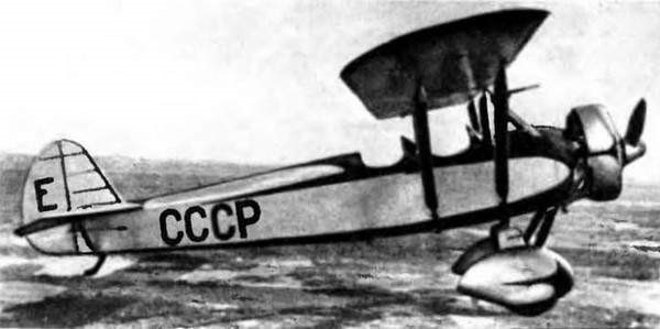
Among the light aircraft created in the early years of the Second Five Year Plan of the USSR stands a small airplane built by a group of engineers from the Fleet Civil Aviation of Leningrad. The Bedunkovich LK-4 (Leningrad Combined – 4) / NIAI-4 (Russian: Бедункович ЛК-4 (НИАИ-4)) training aircraft designed and built in Leningrad in 1934 at the GVF Air Science-Research Institute in Leningrad (later Academy of Civil Aviation).
The aircraft could, depending on its wing configuration, be used for the different stages of pilot training, lowering production and operating costs.
The designer was the 30-year-old engineer Anatoli Georgevich Bedunkovich and, by keeping the same fuselage and exchanging the wing configuration, the LK-4 could be converted into four aircraft with different performance and behaviour. This made it an ideal model for the preparation of pilots, since with a single aircraft the entire course program could be covered, thus saving not only the number of aircraft, but also the costs related to maintenance.
The LK-4 was designed as a tandem two-seater with basically wood construction with fabric covering in the rear region of the fuselage, wings and tail.
The wings were conceived in the form of easily removable individual fixed rope consoles, with a double wooden stringer structure. The upper wing was supported by a cabin-like structure located in the forward part of the fuselage, in front of the cockpit and featured two rigid struts located parallel to each side. The upper plane featured louvered ailerons. Removable plywood flaps designed to reduce landing speed were included in the basic version. A little later on the lower planes, adjustable louver flaps were installed.
The tail unit was of the conventional monoplane type with the horizontal stabilizers braced by struts.
The LK-4 was powered by a 100 hp M-11 radial engine fitted with a Townend ring and driving a two-bladed propeller.
The landing gear was of a fixed type with rubber shock absorbers. The main landers were linked by a bar and featured single wheels with aerodynamic drop-shaped fairings. A fixed skid was located in the tail.
The crew members were in tandem, with the student in the front seat. The cabin equipment was similar to that of the U-21 training aircraft.
LK-4 / LK-4-1
The main or basic version was known simply as LK-4, although in many sources it is named LK-4-1. This sesquiplane device was extremely easy to pilot and was designed for basic training. The upper wing featured large offset and the addition of flaps. This wing was located in a sunshade composition on a cabin-type structure and was braced to the fuselage structure by a pair of parallel rigid struts. The lower wing had a cantilever configuration.
The LK-4-1 was characterized by its great stability in the air and did not go into a spin or stall even in the face of the grossest errors of the students. The empty weight reached 565 kg, while the take-off weight was 790 kg.
Version LK-4-2
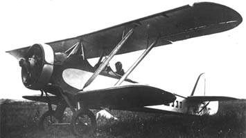
This version was also conceived for basic training, but its piloting was slightly more demanding than that of the LK-4-1 model. The model maintained the sesquiplan configuration but the upper plane lacked offset and did not present the flaps. To achieve this, the upper plane was moved backwards and the lower plane was fixed in an advanced position.
This model was characterized by the ease in the exit of the bit and was able to carry out almost all the high school piloting figures, except the Inmelman due to the lack of motor power
Version LK-4-3
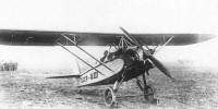
This third version was configured in the form of a high-wing monoplane with a sunshade braced by uprights. The lower wing was removed.
This model was much more demanding in piloting and only those students who had passed the basic preparation stages qualified for its flight. Cruising speed was also higher as a result of decreased aerodynamic drag.
Version LK-4-4
The fourth version was designed for advanced training and featured a monoplane configuration with a low-set wing. In this configuration, the aircraft, both visually and due to its behaviour, was close to the new models of monoplane fighters. This version was quite demanding in the flight technique and for this reason it was only intended for the final stage of the preparation program.
All the transformations were designed to be carried out by the technical personnel of operational aerodromes.
The LK-4 was a collaboration between the LARM (Leningradskie Avioremontnie Masterskie or Leningrad Aviation Repair Shops) and the NIAI. The model was built and successfully tested in 1934 at the NII GVF facilities. During the tests in which 40,000 km were covered, a maximum speed between 150 and 180 km / h was obtained depending on the configuration and a ceiling between 3300 and 4500 meters. These results led the GVF to request serial production of the model.
The LK-4 in a parasol wing monoplane version successfully participated in two competitive flights for light aircraft. Between 1934 and 1936 the aircraft was widely used in the GVF system but the long-awaited series production never materialized.
LK-4-1 – Basic Training Version
Powerplant: 100 hp М-11
Upper plane span: 9.0 m
Lower plane span: 5.7 m
Length: 7.0 m
Wing area: 20.0 m²
Empty weight: 565 kg
Maximum takeoff weight: 790 kg
Fuel + oil weight: 45 kg
Maximum load capacity: 225 kg
Wing loading: 39.5 kg / m²
Power load: 7.9 kg / hp
Weight delivery: 28.45%
Maximum speed: 157 km / h
Landing speed 60 km / h
Ascent time to 1000 m: 6 min
Ascent time to 2000 m: 15.1 min
Ascent time to 3000 m: 30 min
Practical ceiling: 3300 m
Endurance: 2 h
Range: 250 km
Spin time: 21s
Take-off run: 70 m
Landing run: 100 m
Accommodation: 2
LK-4-2 – Sesquiplan version
Powerplant: 100 hp М-11
Upper plane span: 9.0 m
Lower plane span: 5.7 m
Length: 7.0 m
Wing area: 20.0 m²
Empty weight: 558 kg
Maximum takeoff weight: 783 kg
Fuel + oil weight: 45 kg
Maximum load capacity: 225 kg
Wing loading: 39.2 kg / m²
Power load: 7.83 kg / hp
Weight delivery: 28.72%
Maximum speed: 168 km / h
Landing speed 70 km / h
Ascent time to 1000 m: 6 min
Ascent time to 2000 m: 15.3 min
Ascent time to 3000 m: 30 min
Practical ceiling: 3300 m
Endurance: 2 h
Range: 280 km
Spin time: 20s
Take-off run: 80 m
Landing run: 150 m
Accommodation: 2
LK-4-3 – High wing version
Powerplant: 100 hp М-11
Wingspan: 9 m
Wing area: 13 m²
Length: 7 m
Empty weight: 517 kg
Maximum takeoff weight: 742 kg
Fuel + oil weight: 45 kg
Maximum load capacity: 225 kg
Wing loading: 57 kg / m²
Power load: 7.42 kg / hp
Delivery weight:% 30.3
Maximum speed: 177 km / h
Landing speed 80 km / h
Ascent time to 1000 m: 5 min
Ascent time to 2000 m: 13 min
Ascent time to 3000 m: 21.5 min
Practical ceiling: 4500 m
Endurance: 2 h
Range: 300 km
Spin time: 18s
Take-off run: 90 m
Landing run: 170 m
Accommodation: 2
LK-4-4 – Low wing version
Powerplant: 100 hp М-11
Wingspan: 9.7 m
Wing area: 13 m
Length: 7 m
Empty weight: 510 kg
Maximum takeoff weight: 735 kg
Fuel + oil weight 45 kg
Maximum load capacity: 225 kg
Wing loading: 56.6 kg / m²
Power load: 7.35 kg / hp
Delivery weight: 30.6%
Maximum speed: 180 km / h
Landing speed: 90 km / h
Ascent time to: 1000 m: 4.6 min
Ascent time to: 2000 m: 10 min
Ascent time to: 3000 m: 20.2 min
Practical ceiling: 3,815 m
Endurance: 2 h
Range: 300 km
Spin time: 24s
Take-off run: 130 m
Landing run: 220 m
Accommodation: 2
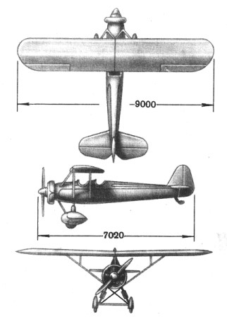
Bedunkovich P-3 / LIG-5
Bedunkovich P-3 (LIG-5) (Russian: Бедункович П-3 (ЛИГ-5)) light training aircraft was designed in 1936 as a development of the LK-4. The aim was to build a single model destined for aviation schools and which would be capable of covering all the stages of preparation of young military pilots in reconnaissance aircraft, biplane fighters and monoplanes. This was intended to lower operating and maintenance costs and reduce the number needed for training. This model was also known as LIG-5 according to the internal numbering of the Leningrad Civil Aviation Fleet Institute.
The change from one version to another was achieved by modifying the wing composition and quantity. The P-3 could be converted into three different versions of the trainer:
P-3 two-seater sesquiplane
Designed as a reconnaissance trainer, this version, due to its characteristics, was quite close to the Polikarpov R-5 reconnaissance biplane. A synchronized firing machine gun was installed on the aircraft through the propeller, an annular mount in the rear cockpit, and underwing mounts for four practice bombs. The cabin equipment included a radio station and a camera.
P-3 single-seat biplane
Designed as a biplane hunting trainer. This version was obtained by disassembling the upper center plane section together with the braces. The consoles of the upper wing were fixed one to the other and the braces were tensioned. A biplane box was obtained with the upper wing type parasol braced and the lower cantilever. The rear cabin was closing.
P-3 single-seater monoplane
Conceived as a monoplane hunting trainer. This model was obtained by eliminating the upper wing in the biplane configuration and replacing the tail empennage. You got an aircraft somewhat similar to the Polikarpov I-16.
The P-3 was designed as a two-seater tandem aircraft built primarily of wood. The powerplant selected was the 330 hp MG-31F engine.
The wing composition varied depending on the version. The wings were constructed of wood with a fabric covering. The cantilever-type lower plane featured trailing edge mechanization and was fixed in all versions. The upper wing was made up of a centroplane and two consoles braced by uprights that were shaped depending on the type of training.
With a detachable monoplane tail structure, it featured conventional type landing gear with tail skid and fixed main landings with aerodynamic fairings.
The construction of the prototype was developed in the workshops of the LII GVF. The aircraft was ready by the summer of 1936 and by February 1937 it had successfully passed factory tests. It was decided to carry out the state tests in Moscow, and airlift it to Moscow. During the flight and due to a pilot error, the plane had an accident in which it was destroyed. It was decided not to rebuild it.
P-3 in sesquiplan configuration
Powerplant: 330 hp MG-31F
Wingspan: 10.6 m
Wing area: 30 m²
Length: 7.5 m
Empty weight: 1100 kg
Maximum takeoff weight: 1560 kg
Fuel + oil weight: 220 kg
Maximum load capacity: 460 kg
Wing loading: 52 kg / m²
Power load: 4.73
Delivery weight: 29.5%
Maximum speed: 210 km / h
Landing speed 80 km / h
Autonomy: 3 h
Range: 500 km
Accommodation: 2
P-3 in biplane configuration
Powerplant: 330 hp MG-31F
Wingspan: 9 m
Wing area: 26 m²
Length: 7.5 m
Empty weight: 960 kg
Maximum takeoff weight: 1260 kg
Fuel + oil weight: 110 kg
Maximum load capacity: 300 kg
Wing loading: 48.4 kg / m²
Power load: 3.82
Delivery weight: 23.8%
Maximum speed: 220 km / h
Landing speed 75 km / h
Autonomy: 1.5 h
Range: 280 km
Accommodation: 1
P-3 in low wing monoplane version
Powerplant: 330 hp MG-31F
Wingspan: 9 m
Wing area: 14 m²
Length: 7.5 m
Empty weight: 850 kg
Maximum takeoff weight: 1150 kg
Fuel + oil weight: 110 kg
Maximum load capacity: 300 kg
Wing loading: 82 kg / m²
Power load: 3.49 kg / hp
Delivery weight: 26%
Maximum speed: 280 km / h
Landing speed 100 km / h
Autonomy: 1.5 h
Range: 300 km
Accommodation: 1
Bedunkovich SJ-1 / LIG-10
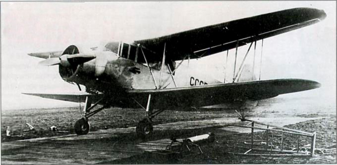
In 1937 a group of engineers from the Civil Air Fleet scheme under the leadership of Anatoli Georgevich Bedunkovich began the development of a new multipurpose aircraft model. This aircraft was designed primarily as an agricultural model, hence its designation SJ-1 (Sielkojozyaisvenni or Agricultural). The projection of the model was carried out in correspondence with the resolution of the GVF of the 26 of August of 1935.
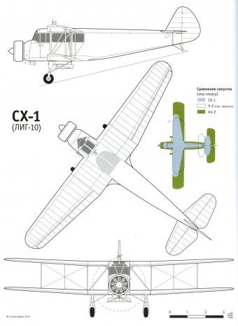
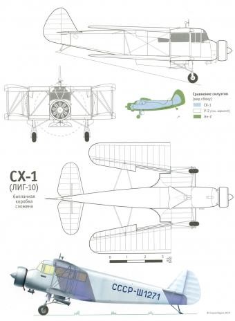
The SJ-1, also known as LIG-10 (Russian: Бедункович СХ-1 (ЛИГ-10)) according to the internal numbering of the Leningrad Civil Aviation Fleet Institute, was designed as a biplane with N-braces and wings without offset. The planes presented a similar configuration with a trapezoidal shape in the constant chord plane. The model was characterized by its good aerodynamics.
The construction of the airplane was mixed, with the use of steel, wood and fabric and it was conceived with all the simplicity that could be tolerated to achieve a cheap and mass-use airplane.
The wings, measuring 41.17 m² in area, had a 12% R-II profile and were made of wood, with a double-spar structure. The shape of the planes was trapezoidal, with a straight leading edge and a trailing edge with a slight inverted arrow. At the trailing edge all half planes had similar ailerons and flaps. The covering of both the wing and the ailerons and flaps was made of fabric.
The wing consoles could be folded back to allow the aircraft to be stored in small hangars or medium-sized barns.
The ample fuselage featured a heavily glazed crew cabin in the position behind the engine. The fuselage structure was skeletal, constructed of lightweight fabric-coated welded steel tubes. The wing bracing tubes were metallic and had a drop-like profile.
The tail unit was made of wood, covered with fabric. The stabilizer could modify its angle of incidence in flight.
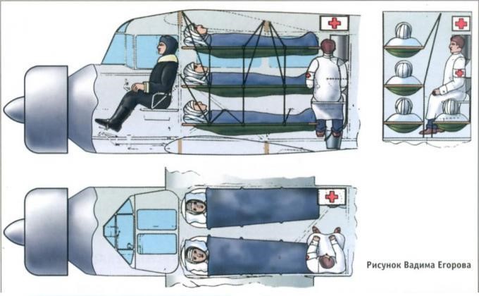
A mechanic or a nurse (in ambulance version) could sit next to the pilot in the flight deck. The cargo cabin, with a capacity of 4.25 cu.m, could be configured in different ways depending on the mission. In the agricultural version, the fuselage housed a 1.8 m3 tank for chemicals or fertilizers. In passenger transport configuration it could accommodate 6 people in two rows of seats. In an ambulance configuration, the possibility of transporting four stretchers and a nurse was foreseen. Depending on the mission, the takeoff weight of the SJ-1 reached 1975 kg (passenger version) or 2150 kg (agricultural version).
The landing gear was of the conventional and fixed type, with single units on the main pyramidal landers and tail skid. In winter the wheels could be replaced by skis. These units were characterized by the wide path of the shock absorbers, which allowed operation on unprepared fields.
The powerplant consisted of a MG-31F piston engine carefully enclosed by a ring-type bonnet. The fuel system consisted of aluminum tanks located in the upper wing centerplane and on both sides of the fuselage.
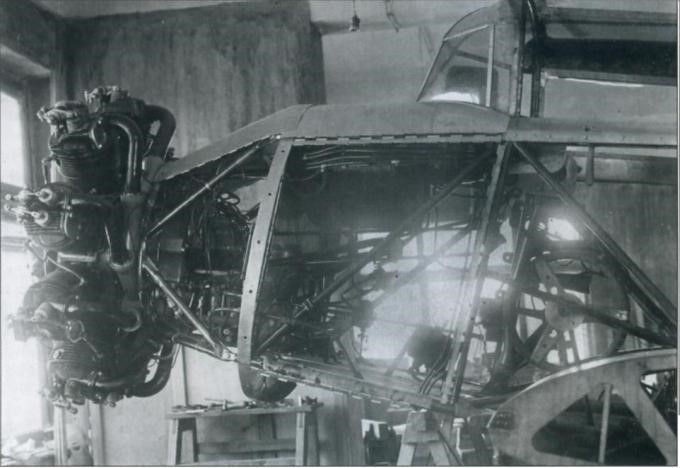
The aircraft featured a fairly complete set of instrumentation and a well-crafted distribution system for chemicals for fumigation.
Built at the Leningrad Aviation Repair Shops, three experimental prototypes were built, which were tested between 1937 and 1938, demonstrating the validity of the concept. Upon completion of the tests, the SJ-1 was handed over to the civil aviation system for testing of the spray systems, as well as the cargo and ambulance variants.
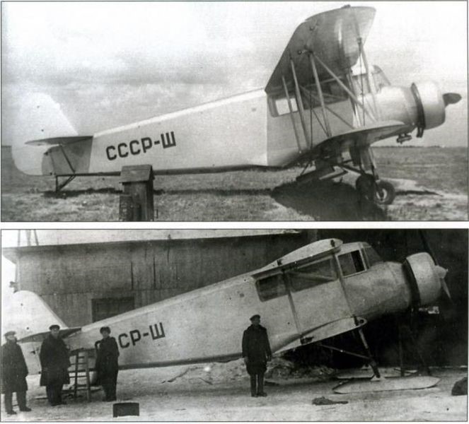
With full load the speed of the SJ-1 exceeded 180 km / h, while the landing speed was only 60 km / h. The model could take off and land on small runways as its run did not exceed 200 meters. With an auxiliary fuel tank the flight range could be extended to 1000 km.
For about a year the position towards the SJ-1 did not change. Only 21 of November of 1939 the President of the Defense Committee VM Molotov received a letter (registered with 04628 no.) Of the NKO substitute AD Loktionov and the head of the GUGVF VS Molokov in which he excelled:
“ The SJ-1 aircraft has been designed, built and tested in the Aeroflot system.
This aircraft is a biplane of simple construction, made of wood and with a 330 hp MG-31 engine.
The SJ-1 is capable of lifting a ton of payload. The results obtained during the state tests show a positive assessment of the aircraft in the different directions of its use.
Maximum speed: 210 km / h
Landing speed: 62 km / h
Take-off run: 150-200 m
Landing stroke: 135-180 m
Practical ceiling: 3000 m
Range with normal fuel: 600 km
These results ensure a wide use in the following variants:
Liaison plane on short lines for 6 passengers;
Ambulance plane – 2 injured on stretchers, two sitting, a doctor and a nurse;
Aircraft specialized in agricultural tasks (fight against harmful species, soil enrichment, fire fighting);
Aerial photography plane;
Thanks to its high load capacity and ability to take off and land in unprepared conditions, the SJ-1 can be used as:
Plane for supplying fuel to aviation and mechanized units.
Technical support plane (transfer of engines, wheels, propellers, etc.
Chemical warfare plane.
The series production of the SJ-1 does not require complex or specialized equipment and can be organized in any aeronautical factory that works with wood or mixed constructions, allowing the S-1, AP and SP models to be taken out of production.
The MG-31 engine installed in the SJ-1 has been extensively tested in the Putilov Stal-2 and according to the special government decision No. 203ss of June 16, 1939 its series production is guaranteed at Factory No. 16.
Taking into account the great need and the wide possibilities of use of the SJ-1 in both the VVS and Aeroflot, the NKO and the GUGVF request to include the SJ-1 in the construction plan for 1940 in one of the factories. “
Unfortunately, this letter was of no consequence. No one specifically can be blamed for this decision. Among the causes we could place that the MG-31 engine was not available, the aeronautical industry management was no longer interested in the biplane scheme and the SJ-1’s performance, despite being good, no longer corresponded to the requirements. of the moment.
In ambulance configuration the SJ-1 was used during the Winter War with Finland in 1940.
Ten years later and using this same scheme, the Antonov An-2 would see the light, one of the most successful biplanes in the history of aviation, with an operating record of almost 70 years. The design of the An-2 prototype drew on the experience accumulated with Bedunkovich’s design.
Bedunkovich SJ-1 (LIG-10)
Powerplant: 330-hp MG-31F
Wingspan: 12.80 m
Wing area: 41.10 m²
Length: 10.70 m
Height: 3.70 m
Empty weight: 1215 kg
Maximum takeoff weight: 2150 kg
Fuel + oil weight: 175 kg
Maximum load capacity: 935 kg
Wing loading: 51.5 kg / m²
Power load: 7.17kg / hp
Delivery weight: 43.5%
Maximum speed: 182 km / h
Landing speed 65 km / h
Practical range: km 350
Practical ceiling: 3,800 m
Take-off run: 210 m
Landing run: 180 m
Bedson Resurgam
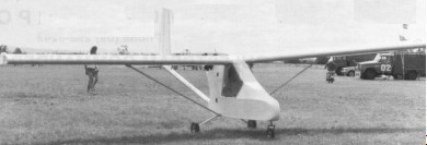
Designed by Gordon Bedson in Australia, the Resurgam is a strut braced high wing pusher, with a fully enclosed cockpit. A true home builders aircraft, the builder has the option of building from the plans up or by purchasing pre-molded fibre glass compo¬nents and the manufactured spar, ribs and undercarriage, by which he can almost half construction time. The Resurgam has been updated and improved over the years.
The Resurgam was originally designed in 1948 to accommodate the JAP engine. A single-seat single-engined high-wing monoplane with conventional three-axis control. Wing has unswept leading and trailing edges, and constant chord; conventional tail. Pitch control by elevator on tail; yaw control by fin-mounted rudder; roll control by 58% -span spoilers (half-span ailerons optional); control inputs through stick for pitch/rod and pedals for yaw. Wing braced from below by struts; wing profile 4415; 100% double-surface. Undercarriage has three wheels in tricycle formation; suspension type wood/glass-fibre suspension on main wheels. Push-right go-right nosewheel steering connected to yaw control. Wood/aluminium-tube fuselage, partially enclosed. Engine mounted at wing height driving pusher propeller.
The front half of the two-part structure is made of spruce and plywood, while the other half consists of a triangulated structure of aluminium-alloy tubes, which supports the engine and extends rearwards to form the empennage. The centre section of the wing is attached to the front fuselage, while the remainder of the wings are attached by six pip pins to facilitate derigging, which can be achieved without breaking any control cables. Wing design consists of a single spruce-and plywood spar, to which plywood-and-foam composite ribs are attached by epoxy, with the joints strengthened by use of glass-fibre. Foam is used for leading and trailing edges, the former being glass-fibre covered and the latter by plywood.
An unusual feature of the Resurgam is that it is designed to accommodate two different roll-control systems. Spoilers are the normal fitment, operated by an aluminium-alloy torque tube which spring loads the spoiler into the closed position, but as you can see from our picture, ailerons can be incorporated instead, operated by the same torque tubes.
In the 1982 London-Paris, when a Konig-engined Resurgam tied with the Huntair Pathfinder as winner of the speed event. The Konig SC430 is a popular fitment to this aircraft, the main alternative being the Skylark MkII.
The Mk.1 and Mk.2 differ in rear fuselage construction with the Mk.2 having a single tube boom.
Engine: Skylark MkII, 24 hp/4800 rpm.
Propeller dia x pitch: 39 x 15 inch, 0.99 x 0.39 m.
Reduction: None
Max static thrust: 135 lb, 61 kg.
Power/area: 0.21 hp/sq.ft, 2.3 hp/sq.m.
Fuel capacity: 4.8 US gal, 4.0 Imp gal, 18.2 litre.
Wing span: 28.0 ft, 8.53 m.
Constant chord: 4.0 ft, 1.22 m.
Sweepback: 0 deg
Tailplane span: 8.0 ft, 2.44 m.
Total wing area: 112 sq.ft, 10.4 sq.m.
Wing aspect ratio: 7.0/1.
Nosewheel dia: 11 inch, 28 cm.
Main wheels dia: 11 inch, 28 cm.
Empty weight: 208 lb, 94 kg.
Max take-off weight: 400 lb, 181 kg.
Payload: 192 lb, 87 kg.
Max wing loading: 3.57 lb/sq.ft, 17.4 kg/sq.m
Max pwr load: 16.7 lb/hp, 7.5 kg/hp.
Load factors design: +3.8
Max level speed: 67 mph, 108 kph.
Cruising speed: 45 mph, 72kph.
Stalling speed: 30 mph, 48 kph.
Max climb rate SL: 460 ft/min, 2.3m/s.
Take-off distance 250ft, 75 m.
Engine: Konig SC430, 30 hp at 4500 rpm.
Propeller: three-blade
Reduction: Belt.
Power per unit area: 0.27 hp/sq.ft, 2.9 hp/sq.m
Wing span: 28.0 ft, 8.53 m.
Fuel capacity: 4.8 US gal, 4.0 Imp gal, 18.2 lt
Constant chord: 4.0 ft, 1.22 m.
Sweepback: 0 deg
Tailplane span: 8.0 ft, 2.44 m.
Total wing area: 112 sq.ft, 10.4 sq.m
Wing aspect ratio: 7.0/1.
Nosewheel diameter: 11 inch, 28 cm
Main wheels diameter: 11 inch, 28 cm.
Empty weight: 205 lb, 93 kg
Max take-off weight: 400 lb, 181 kg.
Payload: 195 lb, 88 kg
Max wing loading: 3.57 lb/sq.ft, 17.4 kg/sq.m.
Max power loading: 13.3 lb/hp, 6.0 kg/hp
Load factors design: +3.8.
Mk.I
Engine: Konig SD570 28hp
Wing span: 9.14m.
Length: 5.94m
Empty wt: 100kg.
MAUW: 200kg
Range: 241 km.
Mk.II
Engine: Konig 430cc-570cc 30 hp. Prop: 132cm 3-blade adj.
Wing span: 8.53 m
Wing area: 10.68 sq m.
Length: 5.64m
Empty wt: 99kg.
Fuel capacity: 19 ltr
Cruise speed: 48-55 kts.
Stall: 27 kts
Construction time: 200-350 hrs.
Bedson
1984: Gordon Bedson and Associates, P.O. Box 6, Bundarra 2359, Australia.
LSA builder
Bédélia Flying Boat 1912
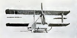
The Bédélia Flying Boat – built in 1912 – was a characteristic biplane with a very large and flat fuselage, acting probably as the floating hull. The wing struts were very large I-styles. Tractor propeller in the front is driven by an engine in the hull, which drives the propeller via a chain.
The machine was temporarily fitted on wheels, with skids. Ailerons were fitted in between the wings. Machine was exhibited on the Salon Paris 1912.
There are more versions of this machine, as the designers developed it further. In the end not very successful.
Bede BD-22L
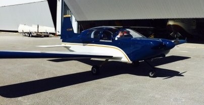
The BD-22 was a two-seat light sport version of the BD-17 with a 47 inch wide cockpit first shown in public in January 2015 as N224BD. Powered by Lycoming O-235 (118 hp) engine. Composite fuselage, metal wings and tricycle undercarriage.
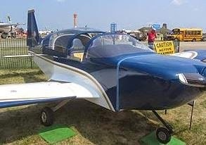
The first BD-22 example built was N224BD which first flew in March 2015. There was only one BD-22, and that was the BD-22L.
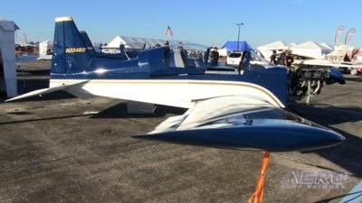
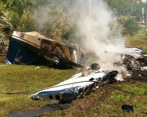
The BD-22L was involved in a fatal crash on 1 April 2015.