Voisin-built Archdeacon glider was acquired and motorized by French inventor Emile Bellamy in 1906.
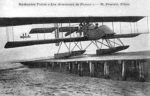
Voisin-built Archdeacon glider was acquired and motorized by French inventor Emile Bellamy in 1906.
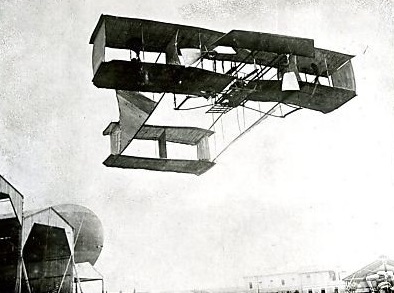
Brothers Aimé and Joseph Behaeghe completed their first aeroplane, a biplane of their own design powered by a 25hp engine, in 1910, after 12 months work. Evidently this aircraft had a limited performance but, undeterred, the brothers went on to build other aircraft.
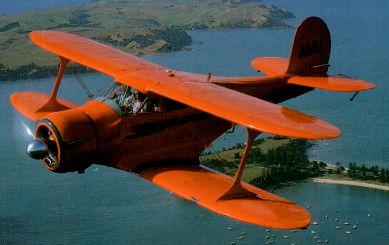
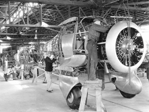
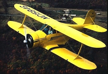
By 1931 Beech resurrected a cabin biplane design started by engineer Ted Wells at Travel Air but rejected by that company’s Curtiss-Wright owners. Aimed at the business executive end of the private owner market — a bold move at the height of the Depression — was the Beech Model 17, continuing the by now-defunct Travel Air series numbers which had ended at CW-16. Apart from its compact dimensions, the four-to-five-seat radial-engine biplane had the unusual layout of its top wing set behind the bottom. This negative or backward stagger arrangement offered several advantages over the more common forward stagger, providing an elegant solution to such problems as pilot visibility and undercarriage location, as well as providing good stall and recovery characteristics.
Beechcraft 17 Staggerwing Article
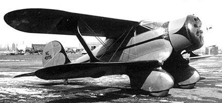
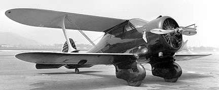
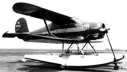
On paper, the 17 promised to be an airplane of outstanding performance for any category, let alone a four-place commercial biplane. A top speed of 200 mph and landing speed of 60 was what they were looking for. The powerplant would be a 420 hp Wright R-975-E2 radial with a Smith controllable prop. While the narrow landing gear was basically fixed, it has enormous streamlined fairings that al¬lowed room for the wheels themselves to retract 0.15m (6in) in flight. The basic structure was welded steel tube, largely fabric-covered; the braced tail unit was conventional; but with a non-swivelling tail-wheel.
Rather than having a neutral stagger the upper wing stacked directly above the lower wing or a positive stagger, with the upper wing leading, as it did on most biplanes, the 17 had a negative stagger: the lower wing was almost 26 inches farther forward than the upper one. The unique wing configuration had three immediate advantages. Visibility had always been a problem with biplanes and high wing monoplanes, but with the upper lead¬ing edge so far back, the pilot had an excellent view. There was an aerodynamic benefit, too: the center of lift of the upper wing was behind the center of gravity, and that of the lower wing was in front of the CG. The lower wing let go first in an approach to a stall, and since the upper wing was still flying, the rearward cen¬ter of lift would automatically bob the nose down, the plane would pick up speed, and the lower wing would be flying again. At the time, this docile stall was an unusual feature for an airplane of such high performance.
A third benefit of the lower wing’s for¬ward position was that it allowed the gear to be wing mounted rather than attached to the fuselage with drag producing struts and brac¬es. This foresight led to the complete retrac¬tion of the gear into the wing and belly, begin¬ning with the B17 model in 1934.
The nickname Staggerwing was soon coined and shows no signs of going away after almost 65 years. The airframe broke no new structural grounds, having wooden wings and steel tube load-bearing fuselage with wooden formers to carry the aerodynamic shape, all but the forward fuselage covered in fabric. Cessna let his old partner use part of the Cessna plant, temporarily closed by the Depression, to begin building Beechcrafts. Careful attention to streamlining achieved Walter Beech’s specifications of 200 mph top speed while landing at 60 mph, a speed range unknown in 1932, on the 420 hp of a Wright R-975 Whirlwind. On 4 November 1932, six months after the factory opened, test pilot W H “Pete” Hill flew the number one Model 17R, NC499N, at a top speed clocked at 201.2 mph.
NC499N was destroyed in a crash on 10 December 1936. In its first two years, the Beech Aircraft Company sold just one airplane, NC58Y. Beech demonstrated the 17R to Tom Loffland who ran a Tulsa oil drilling outfit and had shown an interest during the construction stage. He paid a large deposit and also paid the Beech payrolls while it was being constructed. Work started on the second Model 17 early in 1933, and by July that year the finished aircraft was delivered to its new owner. For his first hundred hours in the airplane, the pilot reported laconically, he had very little idea where it was going during takeoff or landing. It was returned to Beech Co as a trade in mid-1935 and reportedly dismantled
The airplane would have to be improved. As a first step just to see what would happen, he advertised the plane, which already had 420 hp, as available also with the 700 hp Wright Cyclone engine. What happened was an order for one such model from a worsted mill in Maine. Beech built the airplane, but just running up the engine shook the airframe so badly that it continually broke weld joints. In the air it was smoother, and could hit 250 mph, which was faster than any fighter of the time. The pilot who flew it for the customer was given one hundred days to live by his friends, but he confounded them by flying it safely for a year. Thereafter it was sold to Howard Hughes, in whose service it was cracked up on takeoff in the 1937 Bendix Race.
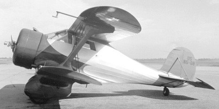
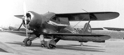
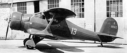
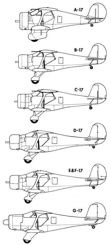
The preproduction model, the A17F with fixed undercarriage, was fitted with a 690-hp Wright R-1820-F11 Cyclone, but although the basic design would appear to give stable flight characteristics, the horsepower was excessive, resulting in “porpoising” due to the short fuselage. There were four fixed gear 17s built – ¬the two 17Rs, an A17F and an A17FS. The A17FS powered with an SR-1820-F3 super-charged Cyclone engine of 710 hp. All stood on tall, stiff, narrow gear and had short coupled fuselages. It was a beautiful airplane in the air but it was very touchy taking off and landing If you were just a second off your timing on the use of the rudder, you were in trouble.
The word on the plane’s high speed spread quickly, and it got a reputation as a hot ship. This notoriety, plus its ground handling characteristics, didn’t help sales. You might also note that the A17F and A17FS had modest little Wright Cyclone engines of 690 and 710 hp, respectively. They went 250 mph, though faster than many military ships and in the air were said to be just as sweet as all models of the Staggerwing were. The A17F, incidentally, was owned at one time by a well known pilot named Howard Hughes.
Meanwhile, Waiter Beech reversed direction, and designed a lightweight, low powered Staggerwing, the B model.
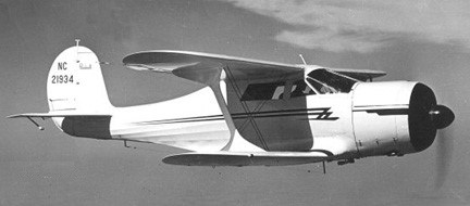
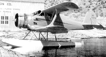
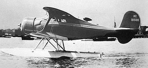
The first production model, built from March 1934 to 1936, was the B17 powered by a 285-hp JacobsR-830-1 L-5 (B17B), a 285-hp Wright R-760-E1 Whirlwind (B17E), a 225-hp Jacobs R-755 L-4 (B17L) or a 420-hp Wright R-975-E2 or 450 hp E3 (B17R). Wingspan was reduced to 32 feet and electrically operated flaps replaced the split rudder for landing drag, but the biggest change was to the undercarriage; a wider, shorter and which now retracted, again by electrical means but with hand-crank backup, folding inwards to house the wheels under the forward fuselage. Other changes included the use of wooden wing spars instead of metal, and a different airfoil. This machine was much more accurately tuned to the market in those still depressed times, and Beech at last began to sell Staggerwings: 18 in 1934 and twice that in 1935 when business began to pick up, as it did for everyone. The Staggerwing had finally achieved commercial success. Commercial success was helped when B17R G-ADLE piloted by H.L.Farquhar completed a 21,332 mile around the world flight in 1935.
Structurally, the Staggerwing uses a mixture of materials and methods. The fuselage has a basic framework of welded steel tube over which is a web of wooden formers and stringers to shape the fabric covering. The wings are all wood: wood spars, wood truss ribs, and, again, fabric skin. The landing gear em¬ploys big metal springs instead of oleos, and is electrically operated. The structure proved strong, except for an era of flutter failures of the top wing, which Beech cured by aileron balancing and plywood stiffening for the wing tips.
The 1936 C model Staggerwing gained a shorter landing gear and had the flaps on the lower wing to improve ground handling which was still a little hairy. A negative four degree angle of incidence was introduced to the tailplane to keep the tail down while landing. Other than these changes, the C17 was identical to the B17, including the choice of engines (with the C17B, E, L and R having the same engines as the respective B17s). Walter Beech never lost an opportunity to market his airplane.
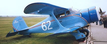
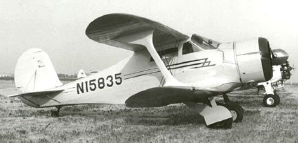
Staggerwings were regularly seen at air shows and did well in racing. The 1936 New York to Los Angeles Bendix cross country race was won by Louise Thaden and copilot Blanche Noyes in a C17R, in 14 hours 44 minutes.
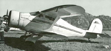
Introduced in 1936 (to 1937), more than 60 C17 were made, but the following year the D17 brought in a number of changes. The most obvious was a rear fuselage extension of 18 inches, while the windscreen profile was altered and the tailplane made a cantilever unit. By now the peripatetic flaps had migrated to their final place on the bottom wing and the ailerons, of similar shape and length, were on the top, while the wings had a new NACA 23012 section and plywood covering outboard of the I-struts. Toe brakes replaced the unloved Johnson bar.
The D17 was built with a range of engines starting with the D17A with 350 hp Wright R-975-E2, followed by the D17R with a 420 hp Wright R-975-E2.
The most popular model was the D17S introduced in 1937, with a 420-hp Pratt & Whitney R-985 Wasp Junior nine-cylinder, air-cooled radial engine, built from 1937 to 1945. The D-17-S obtained its type certificate on 16 July 1937. 66 of the D-17-S had been sold by the time the US entered WW2.
Wartime production of USAAF UC-43 Traveller (based on the D-17S) and USN GB-1s and GB-2s amounted to 412.
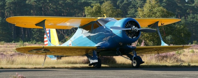
When in 1939 the US Army Air Corps needed a small communications aircraft, the excellent performance of the Model 17 resulted in the procurement of three Model D17s for evaluation under the designation YC-43.
However, it was not until expansion of the USAAF began during 1941-2 that an initial production order for 27 was received, this leading to a total procurement of 207 Beech 17s under the designation UC-43, these being powered by the 336kW Pratt & Whitney R-985-AN-1 engine. After the United States became involved in World War II, an additional 118 civil Model 17s were impressed for military service, and comprising D17R, D17S, F17D, E17B, C17R, D17A, C17B, B17R, C17L, and D17W variants under the respective designations of UC-43A, UC-43B, UC-43C, UC-43D, UC-43E, UC-43F, UC-43G, UC-43H, UC-43J and UC-43K.
The US Navy had acquired a single example of the Staggerwing as early as 1939. This was a 1937 civil C17R which became designated JB-1 [0801]. The designation GB-1 applied to 10 more, equivalent to the civil D17, acquired in 1939 and, later, to eight civil D17s impressed for military service, plus 63 from USAAF inventory [1589/1595, 1897]. Wartime procurement totalled 342 GB-2s (first flying in 1941), of which 105 were supplied to the UK under Lend-Lease, used primarily by the Royal Navy which named them Traveller, a name adopted also by the US Navy, and the RAF. Some went to Brazil.
The E17, built from 1937 to 1944, and the F17, built for the military from 1938 to 1944, were cheaper versions powered by Jacobs with strut-braced tailplane. A 1940 price list shows that an E17B went for $12,380, while the higher ¬powered D17S listed at $18,870. The price in 1936 was $14,500.
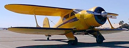
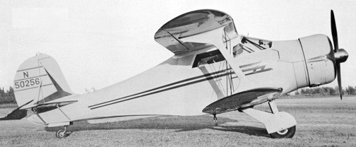
The last in the series was the G17 built from 1946 to 1948. The postwar model was the G17S. Based on the D17S with Pratt & Whitney R-985 Wasp Junior, it was fitted with enclosed gear fairings, cowl flaps, a longer windshield, larger vertical fin, and the engine was moved forward 12 inches with a longer, low-drag engine cowl and more modern disc brakes. At 9700 feet, pulling 65 per cent power, the G17 exceeds 200 mph. Most of the time it cruises at 53 per cent power and 185 mph, burning around 22 gph, with its 450-hp radial. Six fuel tanks (one in each wing, one forward fuselage tank, and one rear fuselage tank) carry 170 gallons to yield a seven-hour endurance or 1300-mile range. Approximately 20 G17 models were built and sold new for $29,000.
Its labour-intensive production methods worked against it, especially when Beechcraft introduced its Model 35 Bonanza at only $8,000. Only 20 of the final model were made in 1946, but were not assembled and sold until orders were received over the next two years. The last G17S, serial number B20, assembled from parts in Texas, flew in 1949.
In all, a total of 781 Staggerwings were built, of which 353 were commercial and 105 to USAF and 320 to USN, excluding 20 built in Japan as C17E.
Beech 17
Wingspan: 32ft 10in
Wing area: 273 sq.ft.
Empty wt: 1600 lb
Normal useful load: 1130 lb.
Normal MAUW: 2730 lb
Max speed: 175 mph.
Cruise: 152 mph
Landing speed: 45 mph.
Climb with full load: 1100 fpm
Service ceiling: 15,000 ft.
Power loading: 14 lb/hp.
17R / 17A
1932 ATC 496
Engine: Wright R-975 Whirlwind, 420 hp.
Wing span: 34’4″
Length: 24’2″
Useful load: 1800 lb
Max speed: 201 mph
Cruise speed: 180 mph
Stall speed: 60 mph
ROC: 1,600 fpm
Ceiling: 21,500 ft.
Range: 960 mi
First flight: 4 Nov 32
Price: $19,000
A17F / A17J
1934 (ATC 548)
Engine: Wright R-1820-F11 Cyclone, 690 hp.
Wingspan: 34’6″
Length: 24’2″
Max speed: 240 mph
Cruise speed: 212 mph
Stall speed: 65 mph
Useful load: 1915 lb
Range: 780 mi
Ceiling: 18,500′
U/C: fixed.
Price $24,500
No. built: 1 NX/NC/NR12583
purchased by Howard Hughes
A17FS
1935 (ATC 577)
Engine: Wright SR-1820-F3 Cyclone, 710 hp.
Wingspan: 34’6″
Length: 24’3″
Max speed: 235 mph
Cruise speed: 215 mph
Stall speed: 65 mph
Range: 750 mi
Ceiling: 20,000′
U/C: fixed.
Price: $30,000
No built: 1 registered by Beech NR12569
transferred to the Bureau of Commerce as NS68
Dismantled c.1937
B17B / SB17B
1934 (ATC 560)
Engine: Jacobs R-830-1 (L-5), 285-hp
Wingspan: 32 ft
Length: 24’6″
Useful load: 1300 lb
Max speed: 185 mph
Cruise speed: 173 mph
Stall speed: 45 mph
Range: 500 mi
Ceiling: 18,000′
U/C: retractable.
Price: $9,000
No built: 2 NC14408, CZ116
CZ116 converted to B17L
SB17B was the twin-float designation
B17E
1935 (ATC 566)
Engine: Wright R-760-E1 Whirlwind, 285-hp
Wingspan: 32 ft
Length: 24’5″
Useful load: 1263 lb
Max speed: 185 mph
Cruise speed: 165 mph
Stall speed: 50 mph
Range: 680 mi
Ceiling: 18,000′
U/C: retractable.
Price: $12,980
No built: 4, NC12593, NC14413, NC14458, NC15412
NC14413 converted to B17R
B17L / SB17L
1934 (ATC 560)
Engine: Jacobs R-755 L-4, 225-hp.
Wingspan: 32 ft.
Useful load: 1350 lb
Max speed: 166 mph / 282 kph
Cruise: 130 kt / 150 mph.
Stall speed: 39 kt / 45 mph / 72 kph
Range: 560 mi
Ceiling: 15,500′
U/C: retractable.
Price: $8,000-8,550
No built: 45
the first Staggerwing on floats, SB17L
B17R / UC-43H
1935 (ATC 579)
Engine: Wright R-975-E3 Whirlwind, 420-hp.
Wingspan: 32 ft.
Useful load: 1362 lb
Max speed: 211 mph
Cruise speed: 202 mph
Stall speed: 55 mph
Range: 760 mi
Ceiling: 22,000′
U/C: retractable.
Price: $14,500
No built: 16
3 to USAAF as C-43H
1 converted from B17E, NC14413
C17B / SC17B / UC-43G
1936 (ATC 602)
Engine: Jacobs L-5, 285 hp
Wing span: 32’0″
Length: 24’5″
Max speed: 185 mph
Cruise speed: 165 mph
Stall speed: 45 mph
Range: 480-680 mi
Price: $9,250
No built: 39, including conversions to C17L, of which 10 to USAAF as UC-43G
1 built as experimental amphibian NC16440
SC17B was twin-float version
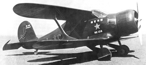
C17E
1936 (ATC 615)
Engine: Wright R-760-E1, 285 hp
Useful load: 1550 lb
Max speed: 185 mph
Cruise speed: 165 mph
Stall speed: 48 mph
Range: 865 mi
Seats: 4
No built: 3, NC15487 plus 2 exported to Japan in 1937, incl. NC15836/J-BAOI
Japanese construction under license of 20 C17Es from 1938-40
C17L / UC-43J
1936 (ATC 602)
Engine: Jacobs L-4, 225hp
Wing span 32ft
MAUW 3165lbs
Useful load: 1340 lb
Max speed: 175mph.
Cruise speed: 166 mph
Stall speed: 45 mph
Range: 560 mi
Price: $8,550
Seats: 4
U/C: retractable
No built: 5, of which 3 to USAAF as UC-43J, 1 converted to C17B, NC16441
C17R / UC-43E / JB-1
1936 (ATC 604)
Engine: Wright R-975-E2, 420 hp
Wingspan: 32’0″
Length: 24’5″
Useful load: 1650 lb
Max speed: 211 mph
Cruise speed: 185 mph
Stall speed: 59 mph
Range: 800 mi
Seats: 4
U/C: retractable
Price: $14,500
No built: 17 of which 1 to USN as JB-1, and five to USAAF as UC-43E
Winner of 1936 Bendix Trophy [NC15835] (p: Louise Thaden & Blanche Noyes)
SC17R with Edo ponyoons.
D17 / GB-1
D17A / UC-43F
1939 (ATC 713)
Engine: Wright R-975-3, 350 hp
Wingspan: 32’0″
Length: 26’11”
Useful load: 1733 lb
Max speed: 180 mph
Cruise speed: 170 mph
Stall speed: 50 mph
Range: 850 mi
Price: $16,350
Seats: 4
U/C: retractable
No built: 8, of which 1 to USAAF as UC-43F
First of the lengthened fuselage models (D-17 through E-17)
D17R / UC-43A
1937 (ATC 638)
Engine: Wright, 420 hp
Wingspan: 32’0″
Length: 26’11”
Useful load: 1680 lb
Max speed: 211 mph
Cruise speed: 202 mph
Stall speed: 60 mph
Range: 825 mi
Seats: 4
U/C: retractable
Price: $18,870
No built: 28, of which 13 to USAAF as UC-43A, plus 2 conversions from D17W – NC17081, NR18562
D17S / UC-43B / SD17S / GB-1
1937 (ATC 649)
Engine: Pratt &Whitney R 985-AN-1 Wasp Junior, 424 hp
Span: 32ft (9.75m)
Wing area: 296.01 sq.ft / 27.5 sq.m
Wing load: 15.79 lb/sq.ft / 77.0 kg/sq.m
Length: 25ft 9in (7.85m)
Height: 10.236 ft / 3.12 m
Max take off weight: 4681.2 lb / 2123.0 kg
Weight empty: 3084.8 lb / 1399.0 kg
Max speed: 212mph (341kmh)
Cruising speed 65%: 148 kt / 274 km/h / 202 mph
Vne: 256mph.
Stall: 61 mph.
Service ceiling: 19997 ft / 6095 m
Range: 840 miles (1350 km)
Seats: 4
U/C: retractable
Price: $18,870
No built: about 50, of which 13 to USAAF as UC-43/UC-43B, 11 to USN as GB-1
SD17S was floatplane
The last D17S NC34R became prototype for G17S
D17W / UC-43K / GB-1
1937
Engine: supercharged P&W R-985-SC-G Wasp, 525-600 hp
Seats: 4
U/C: retractable
No built: 2
1 for Jacqueline Cochran to set speed and altitude records in 1937-38 – NX/NR18562
1 for Frank Hawks, NC17081, later repowered with 420hp Wright R-975
Both converted to D17R, the NX/NR18562 serving in USAAF as UC-43K, NC17081 serving in USN as GB-1
E17B / UC-43D / SE17B
1937 (ATC 641)
Engine: Jacobs L-5, 285 hp
Wingspan: 32’0″
Length: 25’11”
Useful load: 1270 lb
Max speed: 188 mph
Cruise speed: 177 mph
Stall speed: 50 mph
Range: 700 mi
Seats: 4-5
U/C: retractable
Price 1937: $10,490
Price 1939: $12,380
No built: about 52, of which 31 to USAAF as UC-43D
E17L
1937 (ATC 641)
Engine: Jacobs L-4, 225 hp
Useful load: 1335 lb
Max speed: 175 mph
Cruise speed: 166 mph
Stall speed: 50 mph
Seats: 4
U/C: retractable
No built: about 3 – CF-BHA, NC17071, NC18785
Similar to E17B
F17D / UC-43C
1938 (ATC 689)
Engine make/model: 915-cu Jacobs L6MB, 330 hp
Wingspan: 32 ft
Length: 25 ft 11.5 in.
Height: 8 ft
Wing area: 296.5 sq. ft
Max gross weight: 3550–3590lb
Empty weight, std: 2155lb
Fuel capacity: 125 USgals
Wing loading: 10.75 lbs./hp
Seating capacity: 6
Cruise speed: 182 kts
Max speed: 195 mph
Cruise speed: 18 mph
Stall speed: 50 mph
Range: 600 sm
Rate of climb: 1300 fpm
Service ceiling: 18,000 ft
U/C: retractable
Upper-wing ailerons, lower-wing flaps
Price: $13,980
No built: about 60, of which 38 to USAAF as UC-43C
G-17S
1946 (ATC 779)
Engine: 1 x Pratt & Whitney R-985-AN-4 Wasp Junior, 336kW / 450 hp
Max Take-off weight: 1928 kg / 4251 lb
Empty weight: 1270 kg / 2800 lb
Useful load: 1,450 lbs.
Wingspan: 9.75 m / 32 ft 0 in
Length: 8.15 m / 26 ft 9 in
Height: 2.44 m / 8 ft 0 in
Wing area: 27.65 sq.m / 297.62 sq ft
Max. speed: 341 km/h / 212 mph
Max cruise (65% @ 9,700ft.): 175 kts.
Cruise speed: 298 km/h / 185 mph
Normal cruise (53% @ 9,500 ft.): 161 kts.
Stall: 60 mph
Fuel consumption @ normal cruise: 22 USG/hr.
Range @ normal cruise, no res: 1,242 nm.
Seats: 4-5
Fuel capacity: 170 USgals
Initial climb rate: 1,500 fpm
Service ceiling: 20,000 ft
Takeoff distance, 50 ft.: 1,130 ft
Landing distance, 50 ft.: 980 ft
Baggage capacity: 125 lbs.
Endurance: 7 hour
Range: 1300 sm
Price: $29,000
U/C: retractable
No built: 17 to 20
Post-war model, and last of the “Staggerwings,” the final one built in 1949 – NC80321
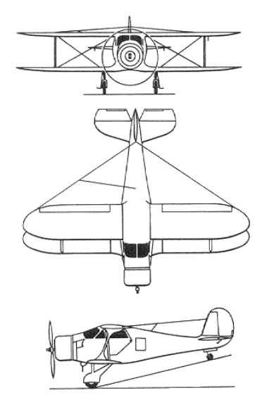
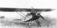
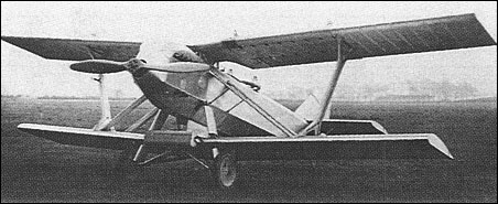
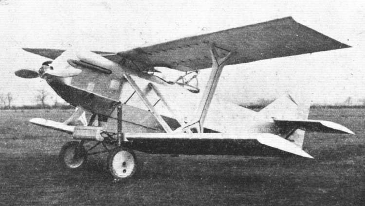
Among the light aircraft created in the early years of the Second Five Year Plan of the USSR stands a small airplane built by a group of engineers from the Fleet Civil Aviation of Leningrad. The Bedunkovich LK-4 (Leningrad Combined – 4) / NIAI-4 (Russian: Бедункович ЛК-4 (НИАИ-4)) training aircraft designed and built in Leningrad in 1934 at the GVF Air Science-Research Institute in Leningrad (later Academy of Civil Aviation).
The aircraft could, depending on its wing configuration, be used for the different stages of pilot training, lowering production and operating costs.
The designer was the 30-year-old engineer Anatoli Georgevich Bedunkovich and, by keeping the same fuselage and exchanging the wing configuration, the LK-4 could be converted into four aircraft with different performance and behaviour. This made it an ideal model for the preparation of pilots, since with a single aircraft the entire course program could be covered, thus saving not only the number of aircraft, but also the costs related to maintenance.
The LK-4 was designed as a tandem two-seater with basically wood construction with fabric covering in the rear region of the fuselage, wings and tail.
The wings were conceived in the form of easily removable individual fixed rope consoles, with a double wooden stringer structure. The upper wing was supported by a cabin-like structure located in the forward part of the fuselage, in front of the cockpit and featured two rigid struts located parallel to each side. The upper plane featured louvered ailerons. Removable plywood flaps designed to reduce landing speed were included in the basic version. A little later on the lower planes, adjustable louver flaps were installed.
The tail unit was of the conventional monoplane type with the horizontal stabilizers braced by struts.
The LK-4 was powered by a 100 hp M-11 radial engine fitted with a Townend ring and driving a two-bladed propeller.
The landing gear was of a fixed type with rubber shock absorbers. The main landers were linked by a bar and featured single wheels with aerodynamic drop-shaped fairings. A fixed skid was located in the tail.
The crew members were in tandem, with the student in the front seat. The cabin equipment was similar to that of the U-21 training aircraft.
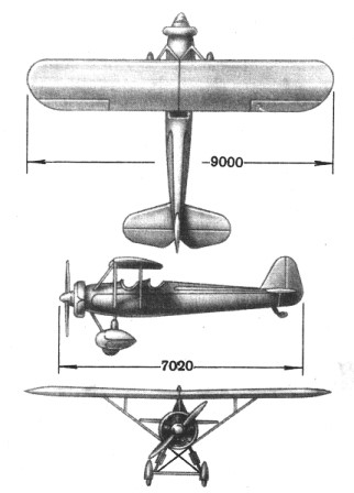
LK-4 / LK-4-1
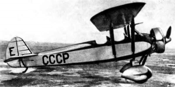
The main or basic version was known simply as LK-4, although in many sources it is named LK-4-1. This sesquiplane device was extremely easy to pilot and was designed for basic training. The upper wing featured large offset and the addition of flaps. This wing was located in a sunshade composition on a cabin-type structure and was braced to the fuselage structure by a pair of parallel rigid struts. The lower wing had a cantilever configuration.
The LK-4-1 was characterized by its great stability in the air and did not go into a spin or stall even in the face of the grossest errors of the students. The empty weight reached 565 kg, while the take-off weight was 790 kg.
Version LK-4-2
This version was also conceived for basic training, but its piloting was slightly more demanding than that of the LK-4-1 model. The model maintained the sesquiplan configuration but the upper plane lacked offset and did not present the flaps. To achieve this, the upper plane was moved backwards and the lower plane was fixed in an advanced position.
This model was characterized by the ease in the exit of the bit and was able to carry out almost all the high school piloting figures, except the Inmelman due to the lack of motor power
Version LK-4-3
This third version was configured in the form of a high-wing monoplane with a sunshade braced by uprights. The lower wing was removed.
This model was much more demanding in piloting and only those students who had passed the basic preparation stages qualified for its flight. Cruising speed was also higher as a result of decreased aerodynamic drag.
Version LK-4-4
The fourth version was designed for advanced training and featured a monoplane configuration with a low-set wing. In this configuration, the aircraft, both visually and due to its behaviour, was close to the new models of monoplane fighters. This version was quite demanding in the flight technique and for this reason it was only intended for the final stage of the preparation program.
All the transformations were designed to be carried out by the technical personnel of operational aerodromes.
The LK-4 was a collaboration between the LARM (Leningradskie Avioremontnie Masterskie or Leningrad Aviation Repair Shops) and the NIAI. The model was built and successfully tested in 1934 at the NII GVF facilities. During the tests in which 40,000 km were covered, a maximum speed between 150 and 180 km / h was obtained depending on the configuration and a ceiling between 3300 and 4500 meters. These results led the GVF to request serial production of the model.
The LK-4 in a parasol wing monoplane version successfully participated in two competitive flights for light aircraft. Between 1934 and 1936 the aircraft was widely used in the GVF system but the long-awaited series production never materialized.
LK-4-1 – Basic Training Version
Powerplant: 100 hp М-11
Upper plane span: 9.0 m
Lower plane span: 5.7 m
Length: 7.0 m
Wing area: 20.0 m²
Empty weight: 565 kg
Maximum takeoff weight: 790 kg
Fuel + oil weight: 45 kg
Maximum load capacity: 225 kg
Wing loading: 39.5 kg / m²
Power load: 7.9 kg / hp
Weight delivery: 28.45%
Maximum speed: 157 km / h
Landing speed 60 km / h
Ascent time to 1000 m: 6 min
Ascent time to 2000 m: 15.1 min
Ascent time to 3000 m: 30 min
Practical ceiling: 3300 m
Endurance: 2 h
Range: 250 km
Spin time: 21s
Take-off run: 70 m
Landing run: 100 m
Accommodation: 2
LK-4-2 – Sesquiplan version
Powerplant: 100 hp М-11
Upper plane span: 9.0 m
Lower plane span: 5.7 m
Length: 7.0 m
Wing area: 20.0 m²
Empty weight: 558 kg
Maximum takeoff weight: 783 kg
Fuel + oil weight: 45 kg
Maximum load capacity: 225 kg
Wing loading: 39.2 kg / m²
Power load: 7.83 kg / hp
Weight delivery: 28.72%
Maximum speed: 168 km / h
Landing speed 70 km / h
Ascent time to 1000 m: 6 min
Ascent time to 2000 m: 15.3 min
Ascent time to 3000 m: 30 min
Practical ceiling: 3300 m
Endurance: 2 h
Range: 280 km
Spin time: 20s
Take-off run: 80 m
Landing run: 150 m
Accommodation: 2
LK-4-3 – High wing version
Powerplant: 100 hp М-11
Wingspan: 9 m
Wing area: 13 m²
Length: 7 m
Empty weight: 517 kg
Maximum takeoff weight: 742 kg
Fuel + oil weight: 45 kg
Maximum load capacity: 225 kg
Wing loading: 57 kg / m²
Power load: 7.42 kg / hp
Delivery weight:% 30.3
Maximum speed: 177 km / h
Landing speed 80 km / h
Ascent time to 1000 m: 5 min
Ascent time to 2000 m: 13 min
Ascent time to 3000 m: 21.5 min
Practical ceiling: 4500 m
Endurance: 2 h
Range: 300 km
Spin time: 18s
Take-off run: 90 m
Landing run: 170 m
Accommodation: 2
LK-4-4 – Low wing version
Powerplant: 100 hp М-11
Wingspan: 9.7 m
Wing area: 13 m
Length: 7 m
Empty weight: 510 kg
Maximum takeoff weight: 735 kg
Fuel + oil weight 45 kg
Maximum load capacity: 225 kg
Wing loading: 56.6 kg / m²
Power load: 7.35 kg / hp
Delivery weight: 30.6%
Maximum speed: 180 km / h
Landing speed: 90 km / h
Ascent time to: 1000 m: 4.6 min
Ascent time to: 2000 m: 10 min
Ascent time to: 3000 m: 20.2 min
Practical ceiling: 3,815 m
Endurance: 2 h
Range: 300 km
Spin time: 24s
Take-off run: 130 m
Landing run: 220 m
Accommodation: 2
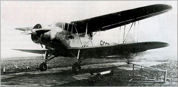
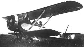
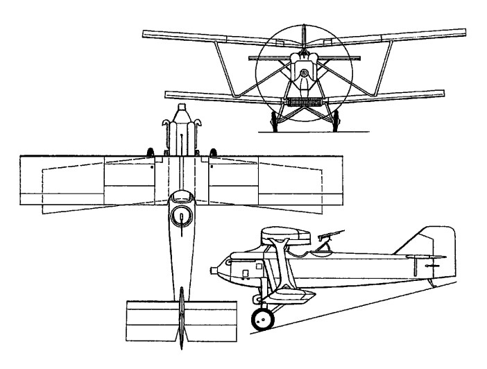
In 1937 a group of engineers from the Civil Air Fleet scheme under the leadership of Anatoli Georgevich Bedunkovich began the development of a new multipurpose aircraft model. This aircraft was designed primarily as an agricultural model, hence its designation SJ-1 (Sielkojozyaisvenni or Agricultural). The projection of the model was carried out in correspondence with the resolution of the GVF of the 26 of August of 1935.
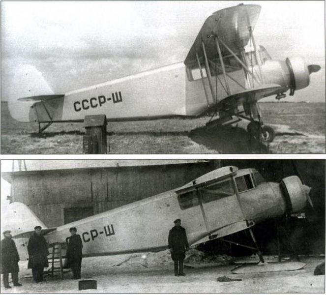
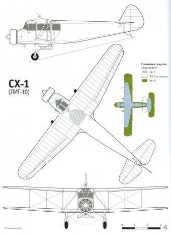
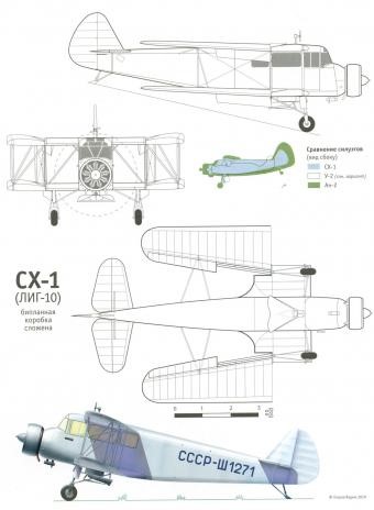
The SJ-1, also known as LIG-10 (Russian: Бедункович СХ-1 (ЛИГ-10)) according to the internal numbering of the Leningrad Civil Aviation Fleet Institute, was designed as a biplane with N-braces and wings without offset. The planes presented a similar configuration with a trapezoidal shape in the constant chord plane. The model was characterized by its good aerodynamics.
The construction of the airplane was mixed, with the use of steel, wood and fabric and it was conceived with all the simplicity that could be tolerated to achieve a cheap and mass-use airplane.
The wings, measuring 41.17 m² in area, had a 12% R-II profile and were made of wood, with a double-spar structure. The shape of the planes was trapezoidal, with a straight leading edge and a trailing edge with a slight inverted arrow. At the trailing edge all half planes had similar ailerons and flaps. The covering of both the wing and the ailerons and flaps was made of fabric.
The wing consoles could be folded back to allow the aircraft to be stored in small hangars or medium-sized barns.
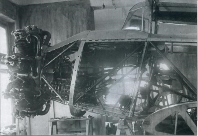
The ample fuselage featured a heavily glazed crew cabin in the position behind the engine. The fuselage structure was skeletal, constructed of lightweight fabric-coated welded steel tubes. The wing bracing tubes were metallic and had a drop-like profile.
The tail unit was made of wood, covered with fabric. The stabilizer could modify its angle of incidence in flight.
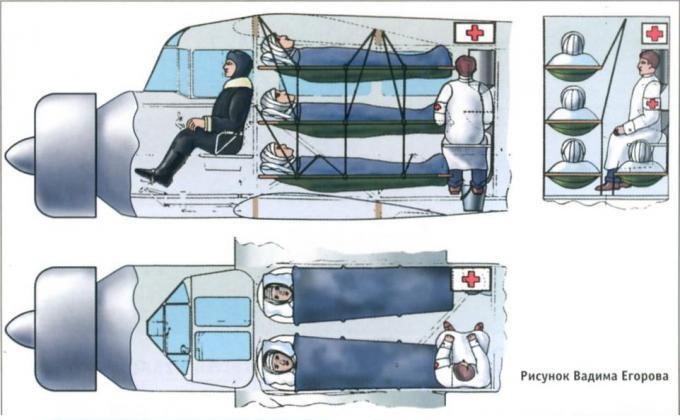
A mechanic or a nurse (in ambulance version) could sit next to the pilot in the flight deck. The cargo cabin, with a capacity of 4.25 cu.m, could be configured in different ways depending on the mission. In the agricultural version, the fuselage housed a 1.8 m3 tank for chemicals or fertilizers. In passenger transport configuration it could accommodate 6 people in two rows of seats. In an ambulance configuration, the possibility of transporting four stretchers and a nurse was foreseen. Depending on the mission, the takeoff weight of the SJ-1 reached 1975 kg (passenger version) or 2150 kg (agricultural version).
The landing gear was of the conventional and fixed type, with single units on the main pyramidal landers and tail skid. In winter the wheels could be replaced by skis. These units were characterized by the wide path of the shock absorbers, which allowed operation on unprepared fields.
The powerplant consisted of a MG-31F piston engine carefully enclosed by a ring-type bonnet. The fuel system consisted of aluminum tanks located in the upper wing centerplane and on both sides of the fuselage.
The aircraft featured a fairly complete set of instrumentation and a well-crafted distribution system for chemicals for fumigation.
Built at the Leningrad Aviation Repair Shops, three experimental prototypes were built, which were tested between 1937 and 1938, demonstrating the validity of the concept. Upon completion of the tests, the SJ-1 was handed over to the civil aviation system for testing of the spray systems, as well as the cargo and ambulance variants.
With full load the speed of the SJ-1 exceeded 180 km / h, while the landing speed was only 60 km / h. The model could take off and land on small runways as its run did not exceed 200 meters. With an auxiliary fuel tank the flight range could be extended to 1000 km.
For about a year the position towards the SJ-1 did not change. Only 21 of November of 1939 the President of the Defense Committee VM Molotov received a letter (registered with 04628 no.) Of the NKO substitute AD Loktionov and the head of the GUGVF VS Molokov in which he excelled:
“ The SJ-1 aircraft has been designed, built and tested in the Aeroflot system.
This aircraft is a biplane of simple construction, made of wood and with a 330 hp MG-31 engine.
The SJ-1 is capable of lifting a ton of payload. The results obtained during the state tests show a positive assessment of the aircraft in the different directions of its use.
Maximum speed: 210 km / h
Landing speed: 62 km / h
Take-off run: 150-200 m
Landing stroke: 135-180 m
Practical ceiling: 3000 m
Range with normal fuel: 600 km
These results ensure a wide use in the following variants:
Liaison plane on short lines for 6 passengers;
Ambulance plane – 2 injured on stretchers, two sitting, a doctor and a nurse;
Aircraft specialized in agricultural tasks (fight against harmful species, soil enrichment, fire fighting);
Aerial photography plane;
Thanks to its high load capacity and ability to take off and land in unprepared conditions, the SJ-1 can be used as:
Plane for supplying fuel to aviation and mechanized units.
Technical support plane (transfer of engines, wheels, propellers, etc.
Chemical warfare plane.
The series production of the SJ-1 does not require complex or specialized equipment and can be organized in any aeronautical factory that works with wood or mixed constructions, allowing the S-1, AP and SP models to be taken out of production.
The MG-31 engine installed in the SJ-1 has been extensively tested in the Putilov Stal-2 and according to the special government decision No. 203ss of June 16, 1939 its series production is guaranteed at Factory No. 16.
Taking into account the great need and the wide possibilities of use of the SJ-1 in both the VVS and Aeroflot, the NKO and the GUGVF request to include the SJ-1 in the construction plan for 1940 in one of the factories. “
Unfortunately, this letter was of no consequence. No one specifically can be blamed for this decision. Among the causes we could place that the MG-31 engine was not available, the aeronautical industry management was no longer interested in the biplane scheme and the SJ-1’s performance, despite being good, no longer corresponded to the requirements. of the moment.
In ambulance configuration the SJ-1 was used during the Winter War with Finland in 1940.
Ten years later and using this same scheme, the Antonov An-2 would see the light, one of the most successful biplanes in the history of aviation, with an operating record of almost 70 years. The design of the An-2 prototype drew on the experience accumulated with Bedunkovich’s design.
Bedunkovich SJ-1 (LIG-10)
Powerplant: 330-hp MG-31F
Wingspan: 12.80 m
Wing area: 41.10 m²
Length: 10.70 m
Height: 3.70 m
Empty weight: 1215 kg
Maximum takeoff weight: 2150 kg
Fuel + oil weight: 175 kg
Maximum load capacity: 935 kg
Wing loading: 51.5 kg / m²
Power load: 7.17kg / hp
Delivery weight: 43.5%
Maximum speed: 182 km / h
Landing speed 65 km / h
Practical range: km 350
Practical ceiling: 3,800 m
Take-off run: 210 m
Landing run: 180 m
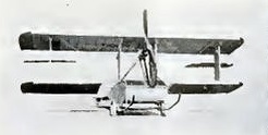
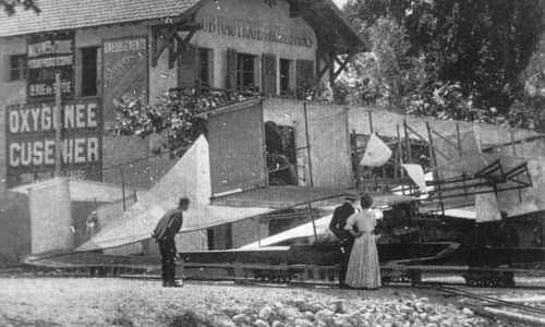
The Bédélia Flying Boat – built in 1912 – was a characteristic biplane with a very large and flat fuselage, acting probably as the floating hull. The wing struts were very large I-styles. Tractor propeller in the front is driven by an engine in the hull, which drives the propeller via a chain.
The machine was temporarily fitted on wheels, with skids. Ailerons were fitted in between the wings. Machine was exhibited on the Salon Paris 1912.
There are more versions of this machine, as the designers developed it further. In the end not very successful.
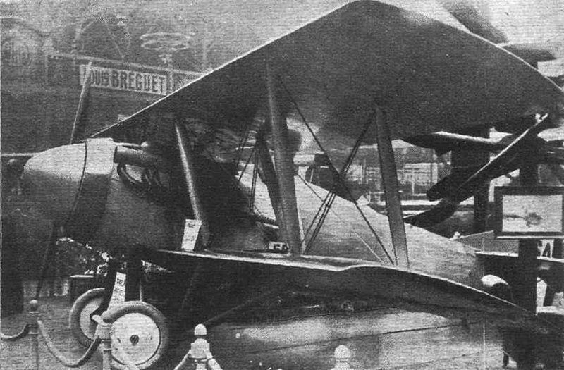
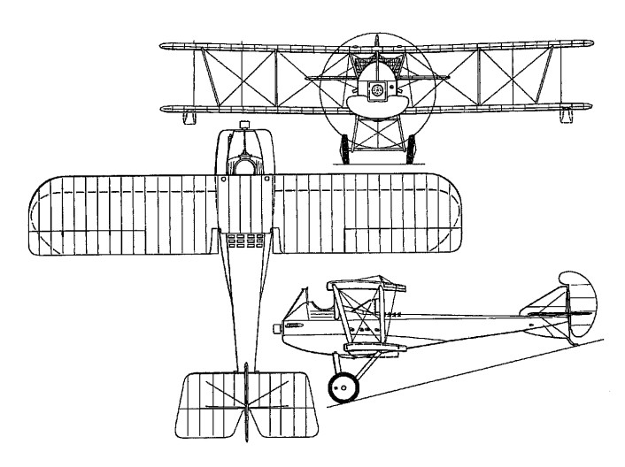
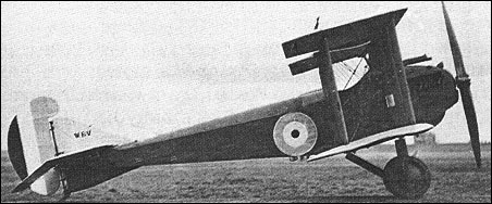
Louis Bechereau established SAB (Societe et Ateliers Bechereau) and was joined in designing a single-seat fighter by Bernard, Bleriot and Birkigt. This, the SAB 1, had the airframe built by Levasseur.
The SAB 1 single-seater fighter, was built by Avions Pierre Levasseur, and was a two-bay biplane powered by a 300 hp Hispano-Suiza 8Fb watercooled eight-cylinder engine. The monocoque fuselage is covered with aluminum in front and fabric in the rear. The engine is totally enclosed in an aluminum cowl, and there is a large spinner over the propeller boss. The radiator is of annular shape and totally surrounding the nose of the machine.
The wing bracing has no struts connecting the top plane with the fuselage. The usual center section struts are replaced by short lengths of lift wires, running from the body to the top of the first pair of inter-plane struts. From the lower ends of these struts, or rather from the bottom spars, two struts converge downwards and inwards, where they are attached to the lower member of the under carriage. The absence of center-section struts and their bracing naturally leaves the pilot’s view unobstructed.
The top surface of both planes is covered with three-ply wood from the leading edge to the rear spar. Ailerons and elevators are balanced by having their leading edges arranged in the form of saw teeth.
The armament consists of four machine guns, two of which are mounted above the fuselage and synchronized in the usual way. The other two are placed in the top plane, some little distance out, and are operated by Bowden control.
Flight testing was initiated during 1918 in competition with the Nieuport 29, five examples being built. Selection of the Nieuport fighter by the Aviation Militaire resulted in discontinuation of further development of the SAB fighter.
Engine: Hispano-Suiza 8Fb, 300 hp
Span, 30 ft 6 1/8 in (9,30 m).
Wing area, 311.09 sq ft (28,90 sq.m)
Length, 22 ft 7 5/8 in (6,90 m).
Height, 8 ft 4 1/3 in (2,55 m).
Empty weight, 1,726 lb (783 kg).
Loaded weight, 2,474 lb (1 122 kg).
Max speed, 130 mph (210 km/h).
Time to 6,560 ft (2 000 m), 5.78 min.
Armament:
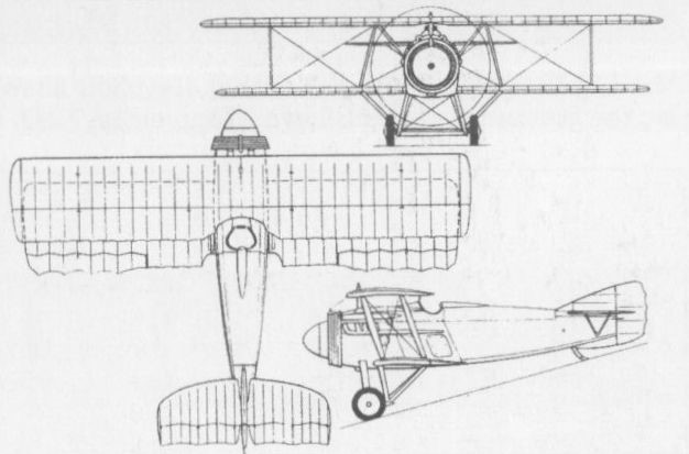
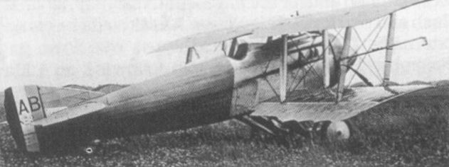
In 1924, the Scottish shipbuilding company of William Beardmore and Company designed a two-seat fighter for Latvia, the W.B.XXVI. Beardmore’s chief designer, W.S. Shackleton produced a wooden single-bay biplane, powered by a Rolls-Royce Eagle engine. The slab-sided fuselage was of hexagonal section, with the crew of two seated in separate cockpits. To reduce drag, the wings had no bracing wires, bracing being solely by means of struts, with a large inter-wing gap. A Lamblin radiator was installed in the leading edge of the lower wing. Instead of the normal Vickers and Lewis machine guns, the aircraft was armed by Beardmore’s own gas-operated Beardmore-Farquhar machine guns.
The prototype first flew some time in 1925. While it proved to be manoeuvrable, it was underpowered, and performance was poor, with the Latvians unwilling to pay for replacement of the Eagle with a more powerful Napier Lion engine. It was sent to Latvia for evaluation in 1926, but was only flown three times in Latvia before it was rejected, and was eventually sent back to Beardmore and scrapped. No more W.B.XXVIs were built.
Engine: 1 × Rolls-Royce Eagle IX, 360 hp (269 kW)
Wingspan: 37 ft 0 in (11.28 m)
Wing area: 356 sq ft (33.1 sq.m)
Length: 27 ft 10½ in (8.50 m)
Empty weight: 2,555 lb (1,162 kg)
Loaded weight: 3,980 lb (1,809 kg)
Maximum speed: 145 mph (233 km/h)
Endurance: 4 hr
Service ceiling: 20,000 ft (6,100 m)
Wing loading: 11.2 lb/sq ft (54.7 sq.m)
Power/mass: 0.09 hp/lb (0.15 kW/kg)
Climb to 15,000 ft: 20 min
Crew: 2
Guns: 2× fixed forward firing Beardmore-Farquhar machine guns and 1 or two flexibly mounted Beardmore-Farquhar machine guns on Scarff ring
The W.B.V single-seat shipboard fighter was developed in parallel with the W.B.IV. It was intended to carry a 37mm Puteaux cannon between the cylinder blocks of its 200hp Hispano-Suiza eight-cylinder water-cooled engine and featured folding wings, a jettisonable undercarriage and inflatable flotation bags beneath the underside of the leading edge of the lower wing. Three prototypes of the W.B.V were ordered, the first flying on 3 December 1917, but the engine-mounted cannon was removed and a more conventional synchronised 7.7mm Vickers gun and a 7.7mm Lewis gun on a tripod ahead of the cockpit mounted. The second prototype W.B.V was completed and flown in 1918, but further development was abandoned before the end of World War I.
Engine: 200hp Hispano-Suiza
Take-off weight: 1134 kg / 2500 lb
Empty weight: 844 kg / 1861 lb
Wingspan: 10.92 m / 35 ft 10 in
Length: 8.10 m / 26 ft 7 in
Height: 3.61 m / 11 ft 10 in
Wing area: 36.60 sq.m / 393.96 sq ft
Max. speed: 180 km/h / 112 mph
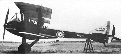
The W.B.IV single-seat shipboard fighter was the first entirely original fighter to be developed by William Beardmore & Company. The 200hp Hispano-Suiza eight-cylinder water-cooled engine was mounted aft of the cockpit and drove the propeller via an extension shaft which passed between the pilot’s legs to provide the best possible view for the pilot, The cockpit was water-tight, a large flotation chamber was provided in the forward fuselage, wingtip floats were incorporated to stabilise the aircraft in the event of it alighting on the water in an emergency, and the undercarriage was jettisonable. The mainplanes could be folded, and The WB.IV was armed with a single synchronised 7.7mm Vickers gun and a 7.7mm Lewis gun mounted on a tripod ahead of the cockpit. Three prototypes of the W.B.IV were ordered, the first of these flying on 12 December 1917, but the other prototypes were not completed.
Engine: 200hp Hispano-Suiza
Take-off weight: 1177 kg / 2595 lb
Empty weight: 932 kg / 2055 lb
Wingspan: 10.92 m / 35 ft 10 in
Length: 8.08 m / 26 ft 6 in
Height: 3.00 m / 9 ft 10 in
Wing area: 32.52 sq.m / 350.04 sq ft
Max. speed: 177 km/h / 110 mph