Designed by Oleg Konstantinovich Antonov between 1926-1929 were the OKA- 3 to 7.
Glider
Antonov OKA-1
First aircraft designed by Oleg Konstantinovich Antonov (1924) was OKA-1 glider.
ANB ANB-M / ANB-I
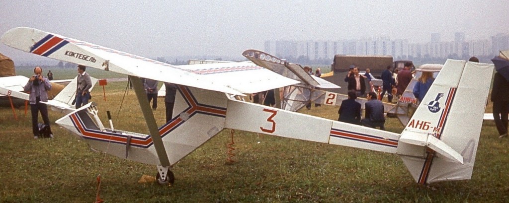
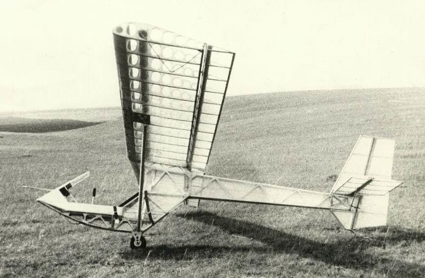
The ANB-M Part103 Sailplane is a full metal primary glider with plans for homebuild.
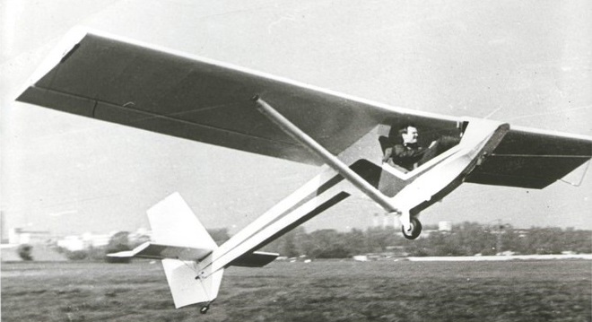
On May 1, 1983 the glider was ready and tested. The ANB-M “Transparent” in Crimea at the All-Union Review Competition of SLA-84 was awarded the 1st prize.
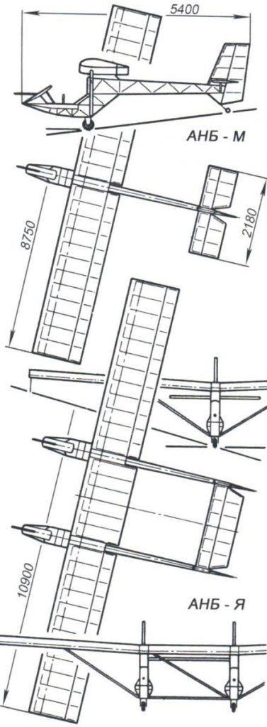
The ANB-I – a modular multi-purpose double glider – was created on the basis of two ANB-M as a result of a simple refinement – two fuselages are fixed parallel at a distance of 2.2 m from each other (the idea was submitted by the designer of gliders V. Janusov).
It turned out a rather exotic design, jokingly called “Snake Gorynych.” The wing span thus became 11 m, and weight – 135 kg.
ANB-M
Wing area: 10.5 sq.m
Empty weight: 70 kg
Take-off weight: 145 kg
Seats: 1
ANB-I
Wing span: 11 m
Weight: 135 kg
ANB
Built the ANB-M PART103 sailplane circa 1983.
The glider was named according to the initial letters of the surnames of its creators – the ANB (Almurzin, Nikitin, and Bogatov).
AMS Flight Carat A
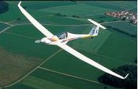
Retractable landing gear, folding propeller, low-noise four-stroke engine, good gliding performance, suitable for trailering, one-man assembly possible, comfortable cockpit.
Stall: 43 kt / 50 mph / 80 kmh
Cruise: 108 kt / 124 mph / 200 kmh
VNE: 135 kt / 155 mph / 250 kmh
Empty Weight: 325 kg / 717 lbs
MTOW Weight: 470 kg / 1036 lbs
Climb Ratio: 700 ft/min / 3.5 m/s
Glide Ratio: 35
Take-off distance (50ft obstacle): 1400 ft / 428 m
Ames M2-F2 / M2-F3AmesM2-F2.jpgAmes M2-F2 / M2-F3
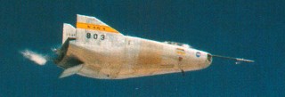
First of NASA’s lifting bodies, the Ames-designed M2 F2 had a convex undersurface with flat topside, twin fins for yaw control, fullspan ventral flap for pitch and split dorsal flaps for roll. First dropped from one of two specially modified B 52 mother ships in July 1966, the M2 F2 was rebuilt after a crash on its 16th flight in May 1967 which seriously injured test pilot Brace Peterson. As the M2 F3, it had a small dorsal fin acting as a flow fence for improved lateral control and completed a farther 27 flights before it was retired in December 1972 having reached a maximum speed of Mach 1.613.
Ames M2-F1 Lifting Body
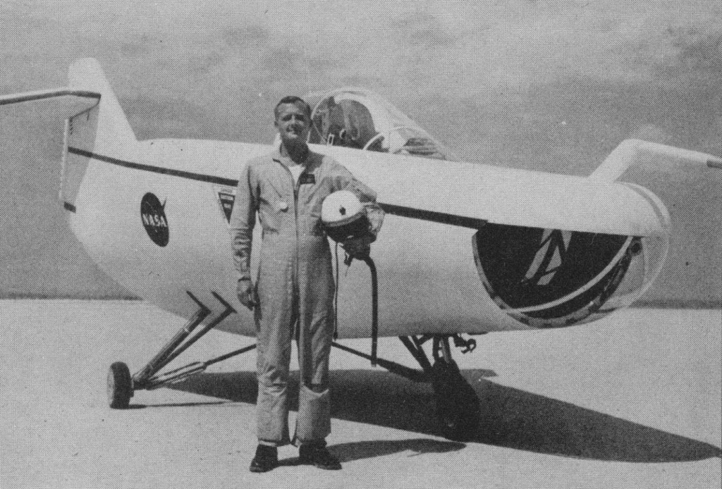
The original idea of lifting bodies was conceived about 1957 by Dr. Alfred J. Eggers Jr., then the assistant director for Research and Development Analysis and Planning at the Ames Aeronautical Laboratory, now the NASA Ames Research Center at Moffett Field, CA.
NASA’s predecessor, the National Advisory Committee for Aeronautics, had earlier been investigating the problems associated with re-entry of missile nose cones. H. Julian Allen, another Ames engineer, determined that a blunt nose cone was a desirable shape to survive the aerodynamic heating associated with re-entry from space. Eggers found that by slightly modifying a symmetrical nose cone shape, aerodynamic lift could be produced. This lift would enable the modified shape to fly back from space rather than plunge to earth in a ballistic trajectory.
These studies by Eggers, Allen, and their associates led to the design known as the M-2, a modified half-cone, rounded on the bottom and flat on top, with a blunt, rounded nose and twin tail-fins. This configuration and those of the later lifting bodies allowed them to be maneuvered both in a lateral and a longitudinal direction so they could be landed on a runway rather than simply parachuting into the ocean as did the contemporary ballistic capsules used in the Mercury, Gemini, and Apollo programs.
In 1962, FRC Director Paul Bikle approved a program to build a lightweight, unpowered lifting body as a prototype to flight test the wingless concept. It was designated the M2-F1. Built by sailplane designer Gus Briegleb, it featured a plywood shell placed over a tubular steel frame crafted at the FRC. Construction was completed in 1963.
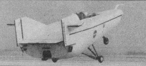
The first flight tests saw the M2-F1 towed aloft by a hopped-up Pontiac convertible driven at speeds up to 120 mph across Rogers Dry Lake. These initial tests produced enough flight data about the M2-F1 to proceed with flights behind a NASA R4D tow plane at greater altitudes. The R4D (the Navy designation of the C-47 or civil DC-3) towed the craft to an altitude of 12,000 ft where it was released to fly freely back to Rogers Dry Lake. NASA research pilot Milt Thompson flew the M2-F1 during the first series of tests.
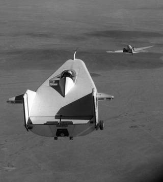
The M2 was towed to 12,000 ft behind the R4D at 115 kts. It glides back at 115 kts with a 4000 fpm rate of descent. Landings are made between 75 and 80 kt.
The M2 has positive response about all axes but is susceptible to turbulence and gusty wind because of limited lateral stability. The M2 carries a 240 lb solid propellant rocket for emergency propulsion during landing or takeoff.
More than 400 ground tows and 77 aircraft tow flights were carried out with the M2-F1 before it was retired. A historical artefact now owned by the Smithsonian’s National Air and Space Museum, the M2-F1 is on long-term loan to NASA Dryden and has been restored to flight-like condition.
Typical glide flights with the M2-F1 lasted several minutes at speeds of 110 to 120 mph.
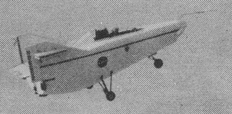
The success of Dryden’s M2-F1 program led to NASA’s development and construction of two heavyweight lifting bodies based on studies at NASA’s Ames and Langley research centers – the M2-F2 and the HL-10, both built by Northrop Corporation. The “M” refers to “manned” and “F” refers to “flight.” “HL” comes from “horizontal landing” and “10” is for the 10th lifting body design that was investigated by Langley.
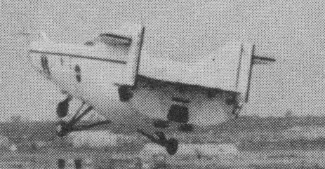
Length: 20 ft
Height: 10 ft
Width: 13 ft
Loaded weight: 1130 lb
AmEagle American Eaglet
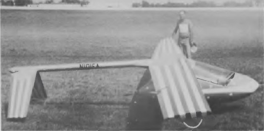
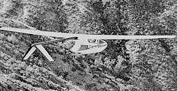
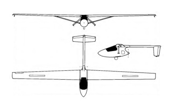
Designed by Larry Haig of Muskegon, Michigan, beginning in September 1974, the American Eaglet is a self-launching sailplane. The type is a high wing monoplane with a pod-and-boom type fuselage with the 12 hp(8.95kW) McCulloch 101B engine mounted aft of the cockpit and driving a 2 ft (60.96 cm)-diameter pusher propeller. The nylon propeller blades fold aft automatically when the engine stops. The cantilever inverted-Vee tailplane and elevators are carried on a tail boom that is a thin-walled 5 in (12.7 cm)-diameter aluminium tube with a moulded glassfibre tailcone. The compact cockpit includes a side-mounted control stick and aft-hinged, single-curved canopy. Construction is largely of glassfibre and urethane foam cores, with some components of aluminium.
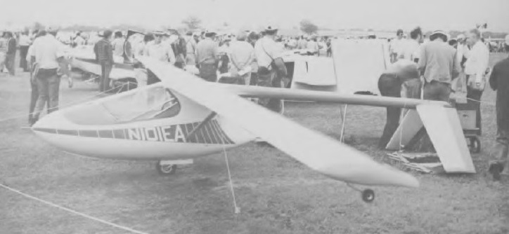
The wings are stressed skin structures with spruce load-bearing spars and a single aluminium tube bracing strut on each side; the spars are surrounded by a urethane foam core, the leading edges and wing tips being of moulded glassfibre, and the urethane core portions are covered with epoxy-bonded precure glassfibre skin. There are no ailerons or flaps, but the functions of these two (ie roll and glide path control) are combined in two spoiler-like surfaces called ‘spoilerons’ at 30% chord on each upper surface towards the wing tip. The forward portion of the fuselage consists of two pre-formed glassfibre half shells pop-riveted to tubular aluminium longerons, the main load-bearing member in the fuselage being the bulkhead which carries the pilot’s seat on one side and the engine mounting on the other. This also carries the tail boom at the top rear, the monowheel at the bottom and the wing spar carry-through at the top, and this bulkhead is an aluminium-skinned urethane foam composite structure. There is a combined pitot tube/lifting handle in the fuselage nose. The inverted-Vee tailplane is very similar to the wings structurally, with an epoxy/glassfibre skin over urethane foam cores, and this V-tail greatly improves control in pitch and yaw, as the prop wash ‘blows’ directly over the tail surfaces; the V-tail also makes spins impossible. The manually-retractable monowheel has an external friction-pad brake, and is supplemented by a tailwheel under the tip of each tailplane.
The American Eaglet can be completed and flown as a pure sailplane, without the engine; the powerplant fitted is a McCulloch 101B single cylinder two-stroke engine developing 12.2hp at 8,000rpm, and drives a two-blade fixed-pitch pusher propeller with nylon plastic blades that fold backwards through 90° when the engine is stopped. The engine is intended only for take-off and self recovery, and is not designed for continuous cross country operation; it can be restarted in flight. A fuel tank of 2 litres (0.5 US gallons) capacity is provided. Fuel tank capacity is generally sufficient for one takeoff and climb to 2,000 feet AGL and three airborne restarts and climbs from 500 feet back up to 2,000 feet. The McCulloch 101B engine was available in only limited quantities, and the West Bend 820 engine will be fitted when availability of the 101B becomes a problem.
The Eaglet was designed for kit building and Larry Haig formed the AmEAGLE Corporation to market it.
Construction of the prototype, registered N101EA, started in June 1975 and this made its first flight on 19 November that year; a second prototype was later flown. A total of 400 kits had been ordered by early 1980, of which 20 had been completed.
Engine: McCulloch 10IB, 8.95 kW / 12 hp
Wing span: 36 ft 0 in /10.97 m
Length: 16 ft 0 in / 4.88 m
Height: 0.91 m / 3 ft 0 in
Wing area: 72 sq.ft / 6.69 sq.m
Empty Weight: 160 lb / 72.5 kg
Payload: 200 lb / 90.5 kg
Gross Weight: 360 lb /163 kg
Water ballast: None
Fuel capacity 2 lt / 0.5 US gal
Wing Load: 5 lb/sq.ft / 41.04 kg/sq.m
Max speed: 115 mph / 100 kt / 185 km/h (in smooth air, power off)
Aspect ratio: 18
Airfoil: Wortmann FX-61-184
Stall speed: 33 kt / 61 km/h
MinSink: 0.76 m/s / 2.50 fps / 1.48 kt at 40 mph / 35 kt / 65 km/h
L/DMax: 27 @ 84 kph/ 45 kt /52 mph
Max rate of climb at sea level: 400 ft/min / 122 m/min
Take-off run: 1,000 ft
No. of Seats: 1
Ambrosini CVV6 Canguro
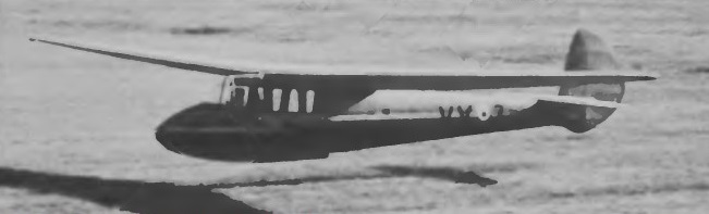
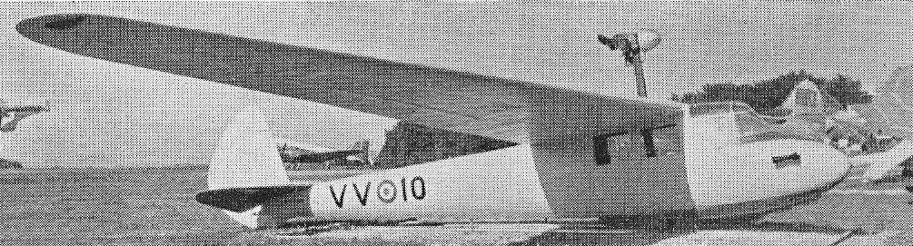
The Canguru was designed in 1939 by the Gliding Institute Polytechnic of Milan (Centro Volo a Vela del Politecnico Di Milano) under the direction of the Engineer Ermenegildo Preti.
The Canguru two-seater is of conventional all-wood and fabric construction, with a high cantilever wing which has a single main spar with a torsionally stiff D-type leading edge; the wing is in two halves and can easily be detached for transport. CVV-type air brakes limit the maximum diving speed to 137mph. The oval-section fuselage is a monocoque structure and the two pilots are seated in tandem, an unusual feature being the location of the second pilot actually beneath the wing rather than ahead of it or in line with the leading edge. The cantilever tail unit has a low-set tailplane.
The CVV 6 Canguru two-seater was developed by the CVV (Centre Volo a Vela del Politecnico di Milano) and built in small numbers by Ambrosini – or Societa Aeronautica Italiana, Ing A. Ambrosini & C. It was also built under licence by Meteor SpA, Costruzioni Aeronautiche.
In addition to the prototype, the Italian air force has ordered 32 copies. The first flew in 1940, only two copies were built during the duration of the war. Others were produced between 1953 and 1955.
A powered prototype Ambrosini CVV6 Canguro, with Italian military number MM100028, was built with a 20 hp flat-twin engine.
Variant:
SAI Ambrosini CVV6 Kangaroo Palas
Canguru
Span: 63 ft 3 in
Length: 26ft 2in
Wing area: 232.5 sq.ft
Aspect ratio: 17
Empty weight: 616 lb
Weight loaded: 1,012 lb
Sinking speed: 1.96 ft/sec
Glide ratio: 30:1
Ambrosini
After incorporation of Societa Aeronautica Italians with Ing A. Ambrosini & Cie, they specialised in fast tourers and sporting monoplanes, though SA11 was biplane. In the immediate pre-war years its Passignano plant was responsible for a successful series of light cabin monoplanes.
In 1939, the chief designer, Sergio Stefanutti, developed an unorthodox tail-first, single-seat fighter, the S.S.4.
The series of light monoplanes had culminated in the S.A.I.7, The series of light monoplanes had culminated in the S.A.I.7 which, of exceptionally clean design and powered by a 280-h.p. Hirsh H.M.508D air-cooled engine, gained the 100-km. closed circuit record for F.A.I. Category I aircraft with a speed of 244 m.p.h. in 1939. The S.A.I.7 possessed excellent flight characteristics. Stefanutti had designed the aircraft with the alternative role of fighter trainer in mind, and a fully militarized trainer prototype flew in 1941. The original prototype featured a long, faired windscreen which extended to the front of the engine cowling to reduce drag, but the military trainer had an orthodox cockpit canopy for the tandem-seated pupil and instructor, and the German Hirsh was replaced by a 280-h.p. Isotta-Fraschini Beta R.C.I0.
The S.A.I.7 trainer basic design were such that Stefanutti contemplated its adaptation as a lightweight interceptor fighter. The initial single-seat model, the S.A.I.I07, was built for research purposes.
The S.A.I.I07 was externally similar to the S.A.I.207, which was built to full fighter requirements and carried an armament of two 20-mm. cannon and two 12.7-mm. machine guns. In dives the S.A.I.207 fighter attained an indicated air speed of 466 m.p.h. at 10,000 ft. (representing a true air speed of 596 m.p.h., or Mach 0.86), and maximum level speed was 357 m.p.h., which was attained on the 750 h.p. provided by an Isotta-Fraschini Delta R.C.40 engine. 2,000 were ordered, though only 13 completed. The type being replaced by proposed production of the SAI 403, work on which finished at war’s end.
Encouraged by the performance of the S.A.I.207, Sergio Stefanutti developed the more ambitious S.A.I.403 Dardo, which featured increased wing area and redesigned tail surfaces. Carrying a similar armament to that of its predecessor, the Dardo was powered by a 750-h.p. Delta R.C.21/60 engine which provided a maximum speed of 403 m.p.h. Large-scale production of the Dardo was planned, but the armistice precluded further development.
Other wartime activities of the S.A.I.-Ambrosini concern were the construction of the AL-12P troop- and cargo-carrying glider designed by Aeronautica Lombarda S.A., and the development of the Ambrosini AR “flying bomb”. Conceived by General Ferdinando Raffaelli as an anti-shipping weapon, the flying bomb was powered by a 1,000-h.p. Fiat A.80 radial engine and was to have been flown off the ground by a pilot who would then bail out, the bomb being directed to its destination by remote radio-control. Flight tests began on 13th June 1943, and four further examples were built at the Venegono plant. Flight trials were successful and a speed of 225-230 m.p.h. was expected, but the bomb was too late to see operational service.
In 1948 the S1001 Grifo broke more records. The S 7 was delivered in small numbers and developed into the Super S 7 (1950s). The F 7 Rondone was 3/4-seat cabin tourer.

