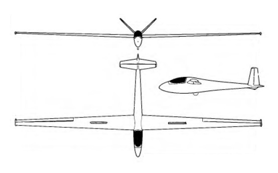
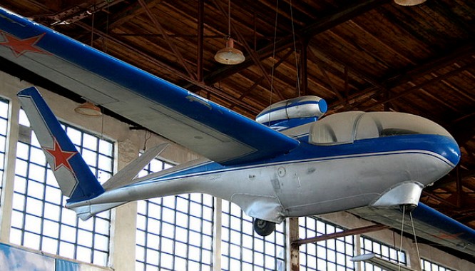
Applebay Chiricahua GA-11

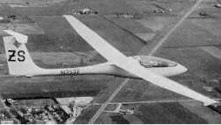
The Chiricahua was designed by George Applebay to comply with the Standard Class rules existing at the time construcion started, 1959, the first flew in 1970. It has a fixed main wheel and top surface Schempp-Hirth type airbrakes for approach control.

Wing span: 15m / 49.2ft
Wing area: 13.77sq.m / 148.2sq.ft
Empty Weight: 268kg / 590lb
Payload: 100kg / 220lb
Gross Weight: 368kg / 819lb
Wing Load: 26.73kg/sq.m / 5.47lb/sq.ft
No. of Seats: 1
Aspect ratio: 16.2
Airfoil: Gottingen 549
Structure: wood, plywood, ceconite

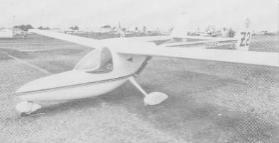
Applebay Zia

The Zia was originally conceived as a tailless motor glider and transformed by Oshkosh 1983 into the twin-boom pusher.

George Applebay entered the ultralight world with a very soaring oriented design, the Zia, whose control system consists of tip rudders, angled so that they work in roll as well as yaw and controlled by stick and pedals through a mixer, and a slotted flap occupying 25% of the canard surface, which provides pitch control. Glidepath control is by flaps which extend to 45 degs.
The tricycle undercarriage has a steerable nosewheel and the braked main wheels are suspended on glass fibre struts reinforced with Kevlar. He designed the Zia according to the JAR22 standard, using composite construction in the main but with Dacron wing covering.
Single seat single engined mid wing monoplane with conventional three axis control. Wing has swept forward leading and trailing edges, and tapering chord; no tail, canard wing. Pitch control by flaps on canard; yaw/roll control by angled tip rudders; control inputs through stick for pitch/yaw/roll and pedals for yaw/roll. Cantilever wing; wing profile; double surface. Undercarriage has three wheels in tricycle formation; suspension on nosewheel and glass fibre/Kevlar suspension on main wheels. Flush right go right nosewheel steering connected to yaw control. Brakes on main wheels. Composite construction fuselage, totally enclosed. Engine mounted at wing height driving pusher propeller. The engine is started by a pull rope either on the ground or for air starting.

Engine: Robin EC25PS, 18 hp.
Power per unit area 0.14 hp/sq.ft, 1.6 hp/sq.m.
Fuel capacity 4.0 US gal, 3.3 Imp gal, 15.0 litre.
Length overall 13.1ft, 4.00m.
Wing span 43.3ft, 13.20m.
Total wing area 125sq.ft, 11.6sq.m.
Empty weight 209 lb, 95kg.
Max take off weight 452 lb, 205kg.
Payload 243 lb, 110kg.
Max wing loading 3.62 lb/sq.ft, 17.7 kg/sq.m.
Max power loading 25.l lb/hp, 11.4kg/hp.
Never exceed speed 81 mph, 130kph.
Cruising speed 59mph, 95 kph.
Stalling speed 28 mph, 45 kph.
Best glide ratio with power off 27/1 at 42 mph, 67 kph.
No. of Seats: 1

Wing span: 14m / 46ft
Wing area: 118 sq.ft / 10.96 sq.m
Empty Weight: 182kg / 400lb
Payload: 113kg / 250lb
Gross Weight: 295kg / 650lb
Wing Load: 26.92kg/sq.m / 5.5lb/sq.ft
Aspect ratio: 18
Airfoil: Wortmann FX 66-197
Structure: fiberglass, carbon spar

Applebay Zuni / Aero Tek Model V

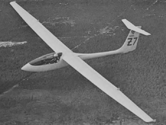
Designed and built by the New Mexico-based firm of Aero Tek under the direction of George Applebay, the Zuni, previously known as the Aero Tek Model V Zuni.

The single-seat 15-meter Zuni, which first flew on 18 November 1976 in New Mexico, was in limited production from 1977 until 1983.

It is sailplane of conventional layout, with a flush transparent canopy and a T-tail. It made its first fight on 18 November 1976, and is of glassfibre construction overall. The cantilever shoulder-mounted wing has a Wortmann wing section developed at the Akaflieg Stuttgart and has full-span camberchanging flaps and ailerons. The flaps and ailerons may be operated separately or interconnected. There is provision for up to 180kg (397lb) of water ballast in the wing, and the undercarriage consists of a single monowheel with a tail bumper fairing under the fin; the forward fuselage tapers to a slimmer boom section carrying the tail unit, and the wings have rectangular inner sections and tapered outer panels.

The fuselage features a roomy cockpit with a semi-reclining seat and in-flight adjustable rudder pedals under a large one-piece canopy. The controls for flaps and landing gear are mounted on the left-hand side of the cockpit, with a side-mounted control stick on the right. The all-moving tailplane is trimmed with a press-button on the control stick.

The two-piece high-set wings contain control linkages which engage automatically when the sailplane is rigged. The interconnecting flaps and ailerons extend the full span of the wings. Flaps can be lowered to +90° for landing or for use as airbrakes. The landing gear consists of a large manually operated retractable monowheel, designed to withstand landings at maximum weight including water ballast, and a tail wheel.

The Zuni II model has carbon spar caps and optional carbon control surfaces, and water ballast capacity is increased to 219 kg. / 483 lb.

Aero-Tek Model V Zuni
Length: 22.047 ft / 6.72 m
Height: 4.265 ft / 1.3 m
Wingspan: 49.213 ft / 15.0 m
Aspect ratio: 22.2
Wing area: 108.716 sq.ft / 10.1 sq.m
Height: 4 ft 8in
Max take off weight: 959.2 lb / 435.0 kg
Weight empty: 493.9 lb / 224.0 kg
Max. speed: 157 kts / 290 km/h / 207mph (in smooth air)
Min sinking speed: 1.71 ft/sec at 50mph
Landing speed: 37 kts / 68 km/h
Cruising speed: 45 kts / 84 km/h
Wing load: 8.82 lb/sq.ft / 43.0 kg/sq.m
Crew: 1

Zuni II
Wing span: 15m / 49.2ft
Wing area: 10.13sq.m / 109sq.ft
Empty Weight: 238kg / 525lb
Payload: 306kg / 675lb
Gross Weight: 544kg / 1000lb
Wing Load: 53.7kg/sq.m / 11.01lb/sq.ft
Water Ballast: 220kg / 483lb
L/DMax: 38@ 98 kph / 53 kt / 61 mph
Aspect ratio: 22
MinSink: 0.55 m/s / 1.8 fps / 1.07 kt
Airfoil: Wortmann mod.
Structure: all fiberglass
No. of Seats: 1

Applebay Zuni
Wing span: 15.0 m (49 ft 2 l/2 in)
Length: 6.71 m (22 ft 0 in)
Height: 1.3 m (4ft 3 in)
Wing area: 10.13 m 2 (109.0 sq ft)
Wing section: Wortmann FX-67K-1707150
Aspect ratio: 22.2
Empty weight: 249 kg (550 lb)
Max weight: 544 kg (1,200 lb)
Water ballast: 181 kg (400 lb)
Max wing loading: 53.7 kg/sq.m (11.0 lb/sq ft)
Max speed: 180 kt (334 km/h)
Stalling speed: 34 kt (63 km/h)
Min sinking at 43.5 kt (80 km/h): 0.52 m (1.71 ft) /sec
Apis

Apris 2

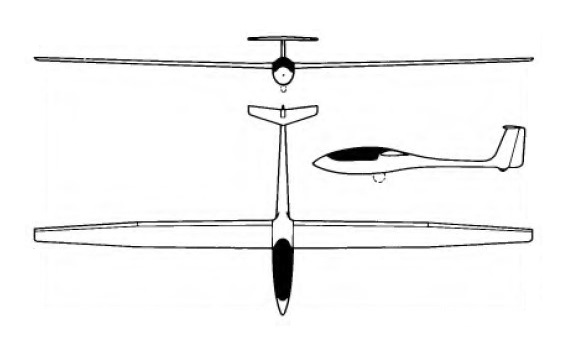
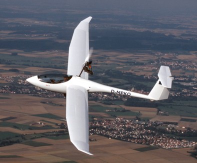
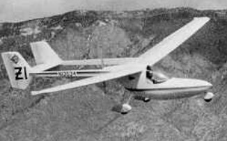
The Apis series includes both a 13- and 15-meter sailplane, is a combination of composite construction and old world craftsmanship. The Apis is intended for the sport flyer, but still holds several world records. They offer a forward-hinged canopy, automatic control hookups, in-flight adjustable rudder pedals, full-span flaperons, blended winglets, and Schempp-Hirth type airbrakes. They also make the Apis M, a 15-meter motorglider.

The Apis 2 is built with CFRP technology with 15 m span and T-tail. The wings are a multi trapezoid with raising tips. Aileron and flaps are interconnected (flaperons) and standard SH airbrakes give short landing approaches.
The spars are connected with two bolts in tongue/tongue technique. Rigging is straight forward and can be easily accomplished by one person. The glider fits in a standard sailplane trailer. The large canopy opens to the side and allows easy access to the ergonomic and roomy cockpit.
The Apis 2 includes a parachute rescue system. Wearing a pilots parachute is therefore not necessary and allows tall pilots to fit in the Apis 2.
The Apis 2 has a large canopy that opens to the side. The back-board can be adjusted continuously, the rudder pedals have some detents, and both can be readjusted during flight. The electric starter button and the throttle are located in the arm rest on the left side. The panel offers space for six instruments with 57 mm diameter in addition to the ECU indicator. One of these six can be replaced by a 80-mm-instrument alternatively. The battery fits into the quick-release rack in the fuselages nose. It energises both the ECU and the instruments.
The Apis 2 cockpit is made up of a double hull. The lightweight hollow section frame of the canopy offers a maximum stiffness in this area.
The Apis 2 takes off under its own power as a self launch glider. Despite the fixed tailwheel it is easy to control on the ground. Two aerodynamic tip wheels help eliminate the need for a wing runner.
The Apis 2 has a fixed gear with a wheel brake on the 4″ wheel.
After a short roll only climb rate is about 2.5 m/s (4.8 kt) at a speed of 80 to 85 km/h (45 kt). After about 150 m (500 ft) it will be airborne and it takes about 290 m (950 ft) over the 50 ft obstacle.
There is almost no trim change flying under engine or in gliding mode or while extending or retracting the engine. The camber changing flaps with a neutral trim will give you a speed range of 80 km/h (43 kt) at +9° to 160 km/h (86 kt) at -6°.
Thermal speed is about 80 km/h (43 kt) and minimum sink is 0.6 m/s (115 fpm). Best glide speed is 95 km/h (52 kt) which will give you a L/D of 39. Landing approach is at 90 km/h (48 kt) with positive flaps. The highly efficient airbrakes allow safe and steep approaches into short airfields. The Apis 2 can be landed with retracted or with extended engine.
The Apis 2 powerplant is an aircooled single cylinder Hirth F33 with intake and exhaust silencer. It generates 27 hp from 303 cc. The 148 cm ground adjustable carbon fibre propeller has been developed by Martin Wezel specially for the Apis 2. The noise level of the Apis 2 is at 57.7 db(A).
The powerplant is retractable. The process is controlled by ECU (Engine Control Unit) an instrument by TL elektronic. The extension of the powerplant is started by switching on the main switch, then the ignition. The ECU then takes over the process and the pilot can start the engine with the starter button. It is not necessary to manually control fuel valve or a choke lever. The ECU is optimizing the engine according to the temperature. During the retraction procedure for the powerplant the ECU is activating the propeller stop as soon as the RPM allows. Then the ECU is controlling the full procedure until the engine is completely stowed away.
The whole process takes about 20 seconds.
German certification in the Ultralight category was issued on 4 September 2003.

Apis 2
Span: 15 m
Wing area: 12.4 sq.m
Aspect ratio: 18.2
Length overall: 6.5 m
Empty weight: from 210 kg
Max. gross weight: 320 kg
Max. load factor: +5.3 / -3.3 g
L/D: 39 at 95 km/h (52 kt)
Min. sink rate: 0.6 m/s at 80 km/h (43 kt)
Flap settings: +9°, +5°, 0°, -3°, -6°
Stall: 35 kt / 40 mph / 65 kmh
Cruise: 81 kt / 93 mph / 150 kmh
VNE: 200 km/h (108 kt)
Engine: Hirth F 33 B, 27 PS / 19.3 kW
Carburetor: Mikuni membrane carburetor
Drive: Poly-V-belt 1:2.5
Propeller: Wezel 2-blade CFRPØ 1.48 m
Fueltank: 14 liter
Fuel consumption while climbing: 9 l/h
Noise level: 57.7 dB(A)

Apis 15M
Cruise: 51 mph
Stall: 36 mph
Aspect Ratio: 17-1
L/D: 40:1
Min sink: 115 fpm
Empty weight: 327 lb
Gross weight: 661 lb
Length: 20.6 ft
Wing span: 49.2 ft
Wing area: 132 sq.ft
Cockpit width: 32 in
Landing gear: tailwheel
Seats: 1

Apis M
Cruise: 56 mph
Stall: 36 mph
Aspect Ratio: 17-1
L/D: 40:1
Min sink: 115 fpm
Engine: Rotax 447, 40 hp
Fuel cap: 3.5 USG
Empty weight: 445 lb
Gross weight: 710 lb
Length: 20.6 ft
Wing span: 49.2 ft
Wing area: 132 sq.ft
Cockpit width: 32 in
Landing gear: tailwheel
Seats: 1

Apis Electric Self-Launch
Cruise: 51 mph
Stall: 36 mph
Aspect Ratio: 18.35-1
L/D: 40:1
Min sink: 108 fpm
Engine: Brushless DC, 13 kW
Empty weight: 452 lb
Gross weight: 710 lb
Length: 20.6 ft
Wing span: 49.2 ft
Wing area: 132 sq.ft
Cockpit width: 32 in
Landing gear: tailwheel
Seats: 1

Antonov A-40 Krylya Tanka / KT  

During the 1940 occupation of Bessarabia, light tanks may have been dropped from a few meters up by TB-3 bombers, which as long as the gearbox was in neutral, would allow them to roll to a stop.

The biggest problem with air-dropping vehicles is that their crews drop separately, and may be delayed or prevented from bringing them into action. Gliders allow crews to arrive at the drop zone along with their vehicles. They also minimize exposure of the valuable towing aircraft, which need not appear over the battlefield. So the Soviet Air Force ordered Oleg Antonov to design a glider for landing tanks.

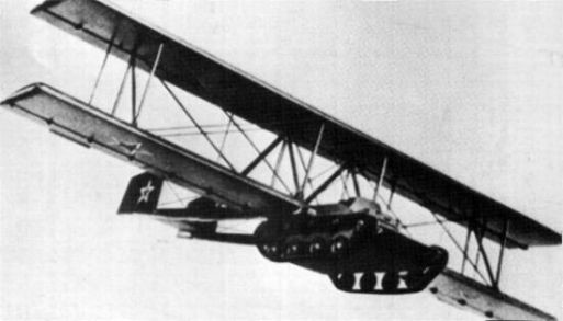
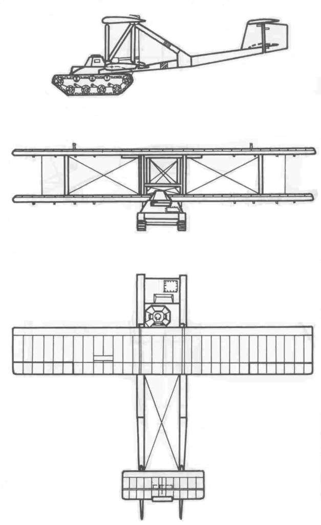
Instead of building a glider, he added a detachable cradle to a T-60 light tank bearing large wood and fabric biplane wings and a twin tail, the Antonov A-40 Krylya Tanka (Russian: крылья танка, meaning “tank wings”). Such a tank could glide into the battlefield, drop its wings, and be ready to fight within minutes.

One T-60 was converted into a glider in 1942, intended to be towed by a Petlyakov Pe-8 or a Tupolev TB-3. The tank was lightened for air use by removing its armament, ammunition and headlights, and leaving a very limited amount of fuel. Even with the modifications, the TB-3 bomber had to ditch the glider during its only flight, on September 2, 1942, to avoid crashing, due to the T-60’s extreme drag (although the tank reportedly glided smoothly). The A-40 was piloted by the famous Soviet experimental glider pilot Sergei Anokhin. The T-60 landed in a field near the airdrome, and after dropping the glider wings and tail, the driver returned it to its base.

Due to the lack of a sufficiently-powerful aircraft to tow it at the required 160 km/h (99 mph), the project was abandoned.

Crew: Two
Capacity: 1 × T-60 tank
Length: 12.06 m (39 ft 6¾ in)
Wingspan: 18.00 m (59 ft 0¾ in)
Wing area: 85.8 m2 (923.5 ft2)
Empty weight: 2,004 kg (4,418 lb)
Gross weight: 7,804 kg (17,205 lb)

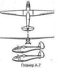
Antonov A-7

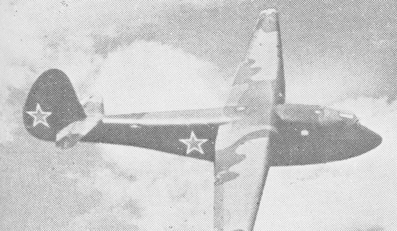
The Antonov A-7 won a design competition held in December 1940 for a “partisan transport glider.

In September 1941 the Germans were approaching Voronezh, but even under these circumstances the aviation factory continued to deliver Il-2 assault aircraft to the front. At the beginning of September 1941, the decision was made to evacuate Factory No. 18 and OKB-31 led by Moscaliov.

The new production base was established in the Siberian village of Zavodoukovsk, located in the Tyumen Oblast, where a new factory was organized that was numbered 499. AS Moscaliov was selected as director and main constructor.

Some time later the factory began to deliver the Antonov A-7 7-seater landing glider productions and a little later the A-2 training gliders, from the same manufacturer.

Some 400 were built.

Wingspan: 62 ft 3 in
Length: 37 ft 9 in

Antonov A-15 Flying Limousine

The single-seater A-15 is a high-performance Open Class design of all-metal construction like the A-11 and A-13 but considerably more refined than these earlier types, and capable of aerobatics, spinning and cloud flying. The prototype first flew on 26 March 1960 and the A-15 soon set up a number of records, including the World goal flight distance record of 443 miles / 714.023km in June 1960.

The mid-set wing has a single aluminium main spar of box section, and there is a 50 litre (13.2gal) water ballast tank built into the wing; wing covering is all-metal. The light alloy ailerons and Fowler flaps have plastic foam filling between the ribs, and there are lift spoilers on the wing upper surfaces. Small end-plate fairings called ‘salmons’ can be fitted on the wing tips. The fuselage is a light alloy semi-monocoque structure and the sideways-opening blown plastic canopy opens to starboard. The pilot’s back-rest and rudder pedals are adjustable, and there is provision for oxygen and radio. Landing gear consists of a retractable sprung monowheel with brake. The cantilever butterfly tail has an included angle of 90° between the tail surfaces; the tailplanes are of light alloy and the elevators of mixed alloy and wood construction with fabric covering.

Wing span: 17 m / 55 ft 9in
Length: 7.2 m / 23 ft 5 in
Wing area: 12.3 sq.m / 132 sq.ft
Empty Weight: 300 kg / 661 lb
Gross Weight: 380 kg/ 838 lb
Wing Load: 30.89 kg/sq.m / 6.32 lb/sq.ft
Water Ballast: 50 kg / 110 lb
Aspect ratio: 24
Airfoil: NACA 64s618/633616
Max speed: 155mph / 135 kt / 250 km/h (in smooth air)
Max aero-tow speed: 87mph
Max rough air speed: 135 kt / 250 km/h
Stalling speed 29.5 kt / 55 km/h
MinSink @ 48.5kt (90kph): 0.63m (2.07ft)/sec
Best glide ratio: 40:1 at 62 mph / 54 kt / 100 km/h
Structure: Aluminium Alloy
Seats: 1
No. Built: 350

Antonov A–13

Antonov A13-M

Developed in parallel with the Antonov A-11, and making its first flight exactly a week before the latter, the A-13 utilises the same fuselage, undercarriage and tail unit as the A-11 married to a shorter span (39 ft 8.5 in) wing of lower aspect ratio for aerobatic training. This wing is very similar in construction to the A-11’s, with a single spar in the root and two spars in the outer wings, and fabric covering aft of the main spar, but flaps are not fitted and the fabriccovered ailerons are not slotted. There are lift spoilers in the upper surfaces. The shorter span wing results in a higher wing loading of 7.07lb/sq ft and a much higher minimum sinking speed of 3.74ft/sec.

Altogether about 350 examples of the A-11 and A-13 were built.

Lyulka has produced the small TS-31M turbojet, which weighing only 51 lb (23 kg) and affording a thrust of 121 lb (55 kgp), is used by the Antonov A13 powered glider.

A-13
Span: 39 ft 8.5 in
Length: 19 ft 8.5 in
Wing area: 112.4 sq.ft
Aspect ratio: 13.8
Empty weight: 560 lb
Max take-off weight: 794 lb
Max speed: 217 mph (in smooth air)
Max aero-tow speed: 124 mph
Min sinking speed: 3.74 ft/sec at 60 mph
Best glide ratio: 25:1 at 70 mph

A13-M
Crew: one pilot
Length: 6.4 m (21 ft 0 in)
Wingspan: 12.1 m (39 ft 8 in)
Height: 1.6 m (5 ft 3 in)
Wing area: 10.4 sq.m (112 sq.ft)
Aspect ratio: 14:1
Empty weight: 270 kg (600 lb)
Gross weight: 360 kg (800 lb)
Maximum speed: 400 km/h (250 mph)
Maximum glide ratio: 25:1
Rate of sink: 1.1 m/s (220 ft/min)