Belyayev BP-2 / TsAGI-2

The Belyayev BP-2 (TsAGI-2) (Russian: БеляевБП-2 (ЦАГИ-2)), was an inverted arrow wing glider developed by Víctor Belyayev to test the effectiveness of this wing composition. Only one copy was produced.

In August 1933 Belyayev participated as a member of the TsAGI technical commission in the IX National Sailing Competitions held in Koktebel, Crimea. The main task of the commission was to check the technical condition of the gliders presented and to grant the authorization to fly. The commission considered that the best exponents were four glider models in a tailless configuration: the BICh-11, BICh-12 and BICh-13 from BI Cheranovski and the LAK-1 glider from a Leningrad flying club.

The presence at the Koktebel competitions prompted Belyayev to implement a conception idea for an airplane. The presence at the TsAGI of AA Sienkov, one of the pioneers of glider construction in the USSR, also played an important role in his decision.

In the TsAGI workshops during the winter of 1933 – 1934, these two specialists began on two new gliders: the BP-1 (TsAGI-1) from Sienkov and the BP-2 (TsAGI-2) from Belyayev. The name BP comes from the term B esxbosti P laner or paneer without glue.

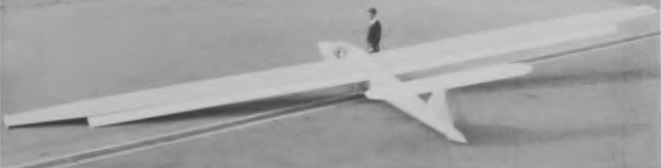
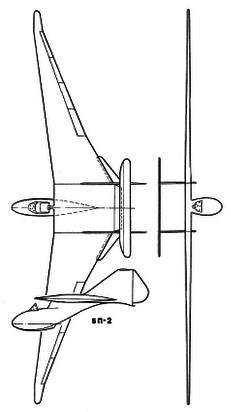
The BP-2 glider was conceived as a flying wing without horizontal tail planes, but with the presence of double keels with rudders.

The wing design was characterized by its large wingspan. The centroplane, designed with an M-6 profile, had a rectangular shape in the plane and the wing consoles with the G-387 profile were fixed to it. The wing, with an area of 18.5 m², presented a configuration with inverted sagging and noticeable stretching towards the ends; standing high above the fuselage. In conjunction with the wing configuration, the entire structure of the glider was conceived seeking the lowest weight and the best possible aerodynamics. The structure incorporated a single spar built in the shape of a box and located at 30% of the wing chord. Four-section ailerons were located on the wing’s trailing edge, designed to ensure the balance of the aircraft and its control. These ailerons covered 9% of the wing surface.

Hanging flaps were located on the trailing edge of the centerplane, designed with the aim of achieving glider balance in flight and improving longitudinal control. In addition to these flaps, two lateral flaps with a smaller area were located at the trailing edge and designed to modify the curvature of the wing profile at the base of the consoles.

The entire wing structure was built in wood and practically in its entirety was covered with plywood (only a small section in the central region of the wing was covered with fabric.

The landing gear consisted of a ski at the bottom of the nacelle and skids under the empennage.

The cockpit was located in the forward part of the centroplane, in front of the wing leading edge, ensuring the necessary centering. This gave the pilot excellent visibility, but in conjunction with the wing configuration impaired the longitudinal stability of the model. To correct this problem on both sides of the central wing area, two large area vertical surfaces topped by a small stabilizer with a large elevator were placed. Large rudders were located in the rear of both keels.

During the design process, an important investigative work was carried out in order to achieve the best wing shape. The configuration of the BP-2 was initially quite criticized in the TsAGI. Several specialists expressed doubts about the flight capabilities of the concept. It was decided to test the model in the wind tunnel. In the TsAGI there was also a 200-meter-long hydrochannel that had an electrically operated trolley for towing the models, which ran the entire length of it. It was decided to use this truck to tow the glider models, thereby quickly and effectively demonstrating that Belyayev’s design it was able to take off and stay in the air without difficulty.

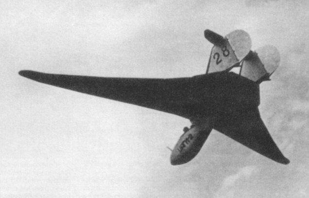
Once finished, first flying in August 1934, the BP-2 was sent to Koktebel to participate in the X National Sailing Competitions, being flown by the pilot DA Koshits. The model demonstrated excellent flight stability and superb control. Pilot Koshits performed Nesterov’s “dead” loop on this glider.
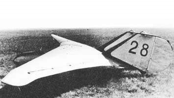
BP-2 glider during the 1934 competitions.

Pilots who had a chance to test it declared that the BP-2 had good flight characteristics and the ailerons were quite effective. It spun quite well. Landing speed was only 40 – 45 km / h. The only defect noted was the poor effectiveness of the rudders, which had to be complemented by the ailerons in flight to achieve the desired effect.

Despite its excellent design the BP-2 was only able to show a glide ratio close to 18 – 1. The main culprits for this limitation were the elevator located on the empennages and the flaps hanging under the centroplane.
After the tests the BP-2 returned to Moscow flying behind a Polikarpov R-5 towplane.

The experience gained with the BP-2 glider served as the basis for the development of the improved BP-3 and the DB-LK bomber.

BP-2
Wingspan: 14.8 m
Wing area: 18.4 m²
Aspect ratio: 11.9
Length: 5.08 m
Height: 2.40 m
Empty weight: 199 kg
Wing loading: 16.5 kg / m²
Minimum descent speed: 1.35 m / s
Stabilizers surface: 0.64 m²
Depth hole area: 1.42 m²
Keel surface: 2.76 m²
Rudder surface area: 1.08 m²
Spoiler area: 1.7 m²
Bede BD-5S

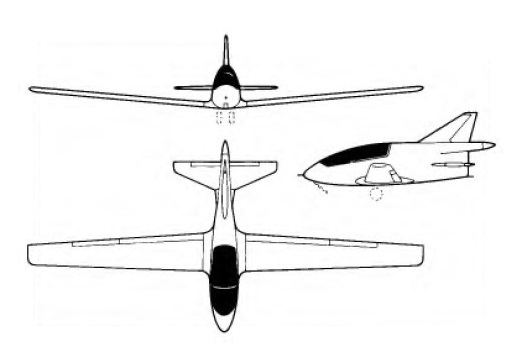
The BD-5S is the sailplane version of the Bede BD-5 Micro single-seat light aircraft, and this engineless version made its first flight in 1975. It differs principally in having a wing span increased by 10ft 5in / 3.17 m, a revised cockpit layout and a redesigned undercarriage in which the backwards-retracting nosewheel of the BD-5 and BD-5J is replaced by a similarly retracting nose skid and the outwards retracting mainwheels are replaced by a pair of side by side twin mainwheels retracting into the fuselage. The main gear door opens forward and can also be used as an air brake. The rear-engined BD-5’s low-set tailplane and rear fuselage shape, with its fairing housing the propeller shaft (in the BD-5) or jet exhaust (in the jet-powered BD-5J), is retained.

The BD-5S, like the powered BD-5 variants, is designed to be suitable for amateur construction from plans and kits. Construction is all-metal and the low wings are attached to the fuselage simply by sliding the tubular spar on to the wing root section and securing it on each side by two bolts. The ailerons are conventional and the flaps extend almost the full trailing edge span and can be lowered through four positions to a maximum of 60°. The pilot is seated under a large detachable framed canopy. A feature is the side-mounted control stick.

BD-5S
Span: 27 ft l0 in / 8.48 m
Length: 13 ft 6.75 in / 4.13 m
Wing area: 60 sq.ft / 5.57 sq.m
Aspect ratio: 12.88
Wing section NACA 641212
Empty weight: 225 lb / 102 kg
Max weight: 425 lb / 193 kg
Max wing loading: 7.09 lb/sq ft / 34.65 kg/sq.m
Min sinking speed: 0.95 m/sec / 3.12 ft/sec at 30 mph
Max diving speed: 174 kt / 322 km/h)
Stalling speed: 34 kt / 63 km/h
Best glide ratio: 23:1
Water ballast: None

Bede Aircraft Corp

The original Bede Aviation Corporation was established 1960 in Kansas to develop an advanced STOL aircraft. An early type was the BD-1 that first flew 1963 and was later produced by others as Yankee Trainer and Traveler. Subsequent designs included BD-4 two/four-seat sporting monoplane of 1970s, and the BD-5 Micro single-seat pusher-engined monoplane and its turbojet-powered derivative as the BD-5J.

The BD-5 and BD-5J were heavily promoted, and the company accepted thousands of orders and deposits before the project ran out of money, causing customers to lose their deposits. As a result, the Federal Trade Commission banned Bede from accepting aircraft kit investments for a period of 10 years.

Following difficult period, company later reestablished as Bede Aircraft Corporation in Missouri, reviving BD-4 and BD-6 for sale in kits and plans forms. BD-12A of 1994 became tandem two-seat variant of BD-5, with larger four-seat BD-14A then put under development.

Beatty-Johl BJ-4

A developed version, the BJ-3A appeared in 1968 and this was followed by the BJ-4, two of which were built for the 1970 World Championships, in which the existing BJ-3 wings were married to a new fuselage and tail unit, the T-tail being replaced with a taller fin and rudder and an all-flying tailplane repositioned on the fuselage behind the rudder.

Beatty-Johl BJ-3

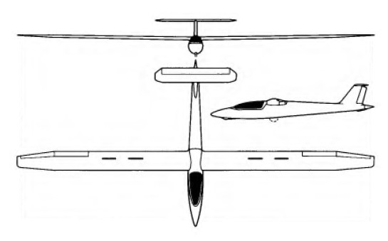
Designed by P. J. Beatty of Johannesburg and W. A.T. Johl especially for South African climatic conditions and the strong thermals experienced in that country, the single-seater BJ-3 was based on experience gained with the successful BJ-2. The prototype, which was built by Performance Sailplanes of Activia Park, Germiston, made its first flight in 1965 and a BJ-3 set up an international speed record over a 500km triangular course on 28 December 1967 of 84 mph.

The BJ-3 is of largely all-metal construction except for the fuselage, which is of glassfibre from the nose to the wing spar, the remainder being a semi-monocoque with duralumin skin and stringers. Landing gear consists of a retractable monowheel aft of the centre of gravity, with a brake, and a retractable nosewheel; in its original form the BJ-3 was to have had a nose-skid. The one-piece plastic canopy hinges to open at the rear, jet fighter fashion, and the BJ-3 is fitted with a full instrument flight panel as well as VHP radio and oxygen. The wings have a basically duralumin load-carrying structure with a wide spar, and are covered with polystyrene foam with an outer protective skin of glassfibre which gives a smooth finish. An unusual feature is the very generous flap area, the Fowler flaps covering no less than 80% of the span and increasing the wing area by 30% when lowered to their full 30°; they have a steel tube spar and, like the main wing structure, are covered in polystyrene foam and glassfibre. Four sets of double DFS-type air brakes are fitted above and below each wing, and the ailerons are of foam and glassfibre. Another unusual feature for a sailplane is a tail braking parachute housed in the tail cone. The fin and rudder are of duralumin, whereas the fixed-incidence tailplane is of plywood-covered spruce construction.

A developed version, the BJ-3A appeared in 1968 and this was followed by the BJ-4, two of which were built for the 1970 World Championships, in which the existing BJ-3 wings were married to a new fuselage and tail unit, the T-tail being replaced with a taller fin and rudder and an all-flying tailplane repositioned on the fuselage behind the rudder.

Beatty-Johl BJ-3
Span: 16.15 m / 52 ft 11.75 in
Length: 7.5 m / 24 ft 7.25 in
Wing area: 12.3 sq.m / 132.4 sq.ft
Wing section: NACA 661 212/0009-64A-0.8
Aspect ratio: 20 (flaps in)
Aspect ratio: 15.82 (flaps extended)
Max weight: 522 kg / 1,151 lb
Water ballast: None
Max wing loading: 42.44 kg/sq.m / 8.69 lb/sq.ft
Max speed: 177 mph / 154 kt / 285 km/h (in smooth air)
Stalling speed: 28.5 kt / 53 km/h
Max aero-tow speed: 138 mph / 120 kt / 222 km/h
Min sinking speed: 0.67 m/sec / 2.2 ft/sec at 46 mph / 40kt / 74 km/h
Best glide ratio: 40:1 at 81 mph / 70kt / 130 km/h

Baynes Bat / Slingsby Sailplanes Baynes Bat

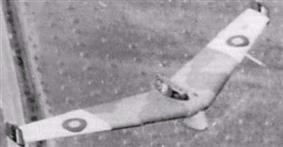
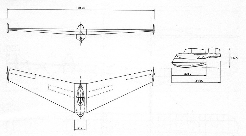
In the late 1930s, armies were looking for a way to airlift heavy military units. There were then no cargo aircraft big enough to lift a tank. A solution which was explored during the Second World War was to tow tanks as gliders, and for this wings had to be added. Most designs were based on straight wings with extended empennage and stabilizers. The design of L.E. Baynes in 1941 was for a 100 ft wing-span “Carrier Wing Glider” consisting chiefly of a swept wing with vertical stabilizers on the wing-tips.

A one-third scale prototype was built entirely of wood in 1943 by Slingsby Sailplanes at Kirkbymoorside, and the Baynes Bat made its first flight in July 1943 at the Airborne Forces Experimental Establishment at RAF Sherburn-in-Elmet, Yorkshire. Most of the test flights were piloted by Flight Lieutenant Robert Kronfeld.

Tests were successful, but the project was abandoned because a suitable tank was not then available and a decision had been made to develop gliders which could carry heavy equipment within their fuselages.

The one Bat which had been built was the first tailless flapped monoplane to be available for research and it was flown extensively by the Royal Aircraft Establishment to test the stability and control of tailless aircraft. The Bat was last seen in 1958, lying behind a hangar at Croydon Airport.

Wingspan: 33 ft 4 in (10.16 m)
Length: 11 ft 4 in (3.46 m)
Wing area: 160.0 sq ft (14.86 m2)
Aspect ratio: 7
Height: 4 ft 4.8 in (1.340 m)
Empty weight: 763 lb (346.1 kg)
Gross weight: 963 lb (436.8 kg)
Maximum speed: 120 mph; 104 kn (193 km/h)
Cruising speed: 80 mph; 70 kn (129 km/h)
Stall speed: 40 mph; 35 kn (64 km/h)
Wing loading: 6.0 lb/sq ft (29.3 kg/m2)
Crew: 1

Baumgartl PB-60

Paul Baumgarti was an Austrian who had worked on three helicopter designs during the war years before emigrating to Brazil. He experimented with a number of light helicopters in the 1950s and 1960s including the single-seat PB-60 unpowered ground-towed rotor kite, and the PB-64 which was an ultra-light single-seater with a minimal tubular fuselage structure. No production of any of these designs was undertaken.

Bates Biplane Glider

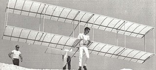
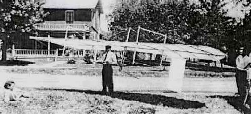
Many “Early Birds” were first airborne in what became known as the Popular Mechanics Glider. Do-it-yourself drawings were published by that magazine in April 1909, from a design by Carl Bates of Chicago. Hundreds of them were built.

The glider, properly registered with the FAA as N2579, was built in 1970 by Robert Mixon and his partner Gary Alfonzo of Miami, Florida. It had a wing span of 20 feet, with a total of 160 square feet of wing area. It made only two flights, both ending with the tail hitting the cliff from which it was launched and the second causing a severely sprained ankle.