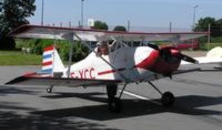
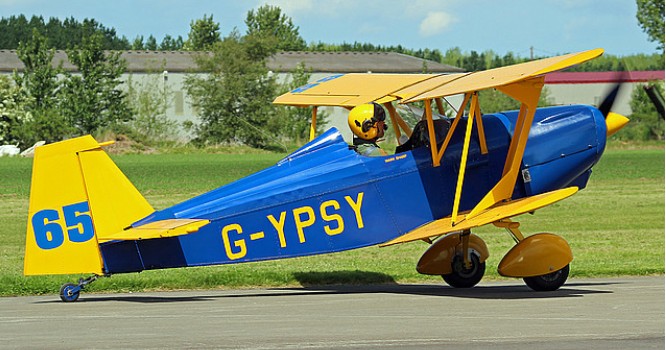
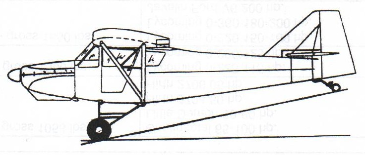
Designed by Björn Andreasson as a homebuilt in 1944 as the single-seat biplane BA-4 was built at Malmo Aviation’s plant at Bulltofta, Sweden.
In 1966 it was designated as the BA-4B c/n 1 registered SE-XBS and was powered by a Continental O-200-A.
The rights to the design were sold to Peter J.C. Phillips who formed Crosby Aviation Ltd to market kits and plans of the BA-4B. The prototype was imported to the UK in 1968 as G-AWPZ.
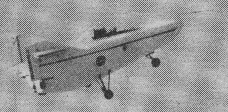
Andreasson BA-4B
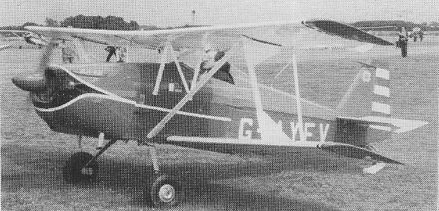
Three aircraft were laid down for initial sales at Knutsford, Cheshire, UK, and all were completed, including G-AYFU, V and W.
Crosby Aviation built G-AYFV
Crosby Aviation offered two versions: the BA-4B with a Rolls-Royce/Continental O-200-A; and the Super BA-4B with a Rolls-Royce/Continental O-240-A.
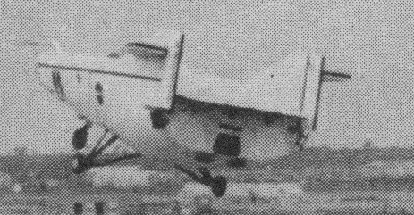
Designed in Mexico as an ag aircraft, the prototype Tauro 300 first flew on 3 December 1968. An improved Tauro 350 with more powerful radial engine (350 hp) followed into production from 1977.
Tauro 300
Tauro 300 Engine: Jacobs R-755-A2M1, 300 hp Wing span: 37 ft 6.5 in / 11.44 m Length: 26 ft 11.25 in / 8.21 m Max cabin length: 3 ft 8 in / 1.12 m Max cabin width: 2 ft 10 in / 0.86 m Max cabin height: 4 ft 3 in / 1.295 m Empty weight: 1973 lb / 895 kg MTOW: 3542 lb / 1606 kg Max cruise SL: 78 kt / 90 mph / 145 kph Max ROC SL: 500 fpm / 152 m/min Service ceiling: 14,000 ft / 4250 m Range max fuel: 202 nm / 233 mi / 375 km Seats: 1 Hopper capacity: 230 USG / 191 Imp.G / 870 lt / 1764 lb / 700 kg
Fabrica de Aviones Anahuac SA, Mexico, was established in 1966 to develop agricultural aircraft suited to national requirements. The rototype Tauro 300 first flew on 3 December 1968. The improved Tauro 350 with a more powerful radial engine (350 hp) followed into production from 1977.
The AMF S-14 is a two-place taildragger modeled after the Adam RA-14. The S-14 was first flown in 1961. It is powered by 85- to 150 hp engines. Its fuselage is a conventional wooden box-girder structure, covered with plastic-coated fabric. The S-14’s wings are a braced high-wing design of all wood and fabric with STOL characteristics. Folding wings and Hoerner wingtips. Lycoming and similar engines 100 to 200 hp are suitable. The AMF-14H has a lighter structure for engines 50 to 115 hp to meet the Sport Aircraft category (LSA). Options include flaps, floats, tricycle gear, extra wide cockpit, rodent proof tail, long range auxiliary tanks, extended wings, variety of engines including diesel.
On June 30, 2019, Falconar Avia Inc closed for business and assets dissolved. The Master Sets (Original Drawings, Plans, Info Kits, Documentation) were available for sale and full transfer of rights included the AMF – S14 “Maranda” S14 D and S14 H for $10,000 USD.
S-14 Engine: Lycoming O-320, 150 hp HP range: 85-200 Wing span: 31.8 ft Wing area: 158 sq.ft Length: 22 ft Height: 7.1 ft Weight empty: 1100 lb Gross: 1850 lb Fuel cap: 18 USG Speed max: 130 mph Cruise: 115 mph Range: 400 sm Stall: 35 mph ROC: 1300 fpm Take-off dist: 100 ft Landing dist: 150 ft Service ceiling: 17,000 ft Seats: 2-3 Landing gear: nose or tail wheel Plans (2010): US$200
Super 14D Engine: Lycoming O-320, 150 hp HP range: 85-200 Wing span: 31.8 ft Wing area: 158 sq.ft Length: 22 ft Height: 7.1 ft Empty weight: 1100 lb Gross weight: 1850 lb Fuel capacity: 18 USG Top speed: 150 mph Cruise: 120 mph Stall: 41 mph Range: 480 sm Rate of climb: 1000 fpm Takeoff dist: 200 ft Landing dist: 180 ft Service ceiling: 17,000 ft Seats: 2-3 Landing gear: nose or tail
AMF Super 14D Maranda Cruise: 120 mph Stall: 39 mph Range: 340 sm Rate of climb: 1000 fpm Takeoff dist: 200 ft Landing dist: 200 ft Engine: Lycoming O-320, 150 hp HP range: 85-200 Fuel capacity: 22 USG Empty weight: 1100 lb Gross weight: 1850 lb Length: 22 ft Wing span: 31.8 ft Wing area: 158sq.ft Cockpit width: 40-46 in Landing gear: nose or tail
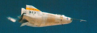
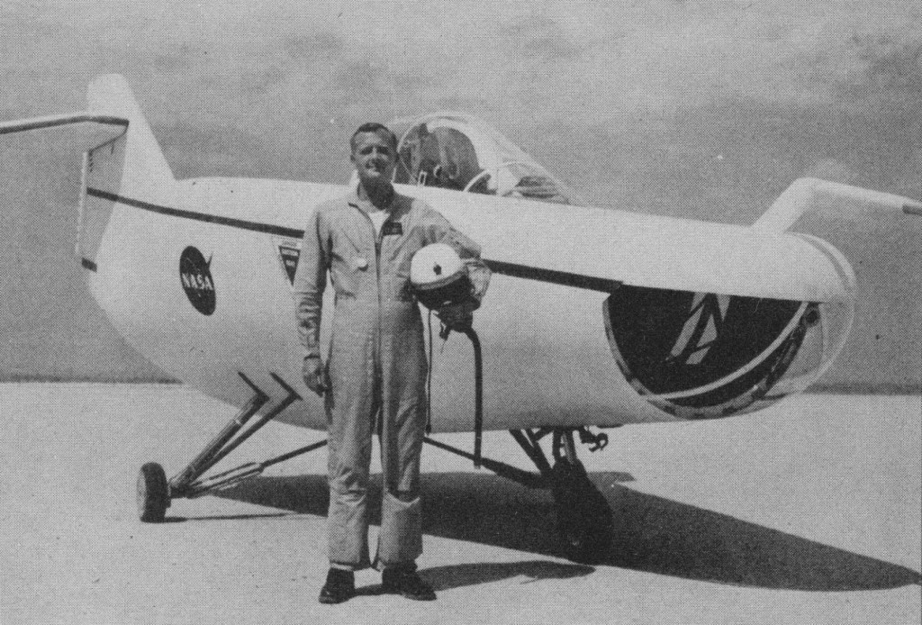
First of NASA’s lifting bodies, the Ames-designed M2 F2 had a convex undersurface with flat topside, twin fins for yaw control, fullspan ventral flap for pitch and split dorsal flaps for roll. First dropped from one of two specially modified B 52 mother ships in July 1966, the M2 F2 was rebuilt after a crash on its 16th flight in May 1967 which seriously injured test pilot Brace Peterson. As the M2 F3, it had a small dorsal fin acting as a flow fence for improved lateral control and completed a farther 27 flights before it was retired in December 1972 having reached a maximum speed of Mach 1.613.
The original idea of lifting bodies was conceived about 1957 by Dr. Alfred J. Eggers Jr., then the assistant director for Research and Development Analysis and Planning at the Ames Aeronautical Laboratory, now the NASA Ames Research Center at Moffett Field, CA.
NASA’s predecessor, the National Advisory Committee for Aeronautics, had earlier been investigating the problems associated with re-entry of missile nose cones. H. Julian Allen, another Ames engineer, determined that a blunt nose cone was a desirable shape to survive the aerodynamic heating associated with re-entry from space. Eggers found that by slightly modifying a symmetrical nose cone shape, aerodynamic lift could be produced. This lift would enable the modified shape to fly back from space rather than plunge to earth in a ballistic trajectory.
These studies by Eggers, Allen, and their associates led to the design known as the M-2, a modified half-cone, rounded on the bottom and flat on top, with a blunt, rounded nose and twin tail-fins. This configuration and those of the later lifting bodies allowed them to be maneuvered both in a lateral and a longitudinal direction so they could be landed on a runway rather than simply parachuting into the ocean as did the contemporary ballistic capsules used in the Mercury, Gemini, and Apollo programs.
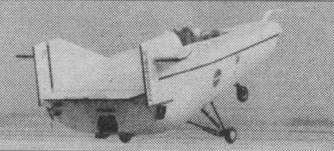
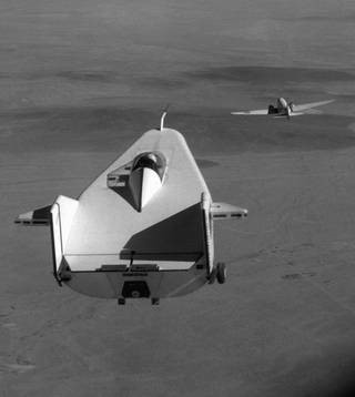
In 1962, FRC Director Paul Bikle approved a program to build a lightweight, unpowered lifting body as a prototype to flight test the wingless concept. It was designated the M2-F1. Built by sailplane designer Gus Briegleb, it featured a plywood shell placed over a tubular steel frame crafted at the FRC. Construction was completed in 1963.
The first flight tests saw the M2-F1 towed aloft by a hopped-up Pontiac convertible driven at speeds up to 120 mph across Rogers Dry Lake. These initial tests produced enough flight data about the M2-F1 to proceed with flights behind a NASA R4D tow plane at greater altitudes. The R4D (the Navy designation of the C-47 or civil DC-3) towed the craft to an altitude of 12,000 ft where it was released to fly freely back to Rogers Dry Lake. NASA research pilot Milt Thompson flew the M2-F1 during the first series of tests.
The M2-F1 Lifting Body being towed behind a C-47
The M2 was towed to 12,000 ft behind the R4D at 115 kts. It glides back at 115 kts with a 4000 fpm rate of descent. Landings are made between 75 and 80 kt.
The M2 has positive response about all axes but is susceptible to turbulence and gusty wind because of limited lateral stability. The M2 carries a 240 lb solid propellant rocket for emergency propulsion during landing or takeoff.
More than 400 ground tows and 77 aircraft tow flights were carried out with the M2-F1 before it was retired. A historical artefact now owned by the Smithsonian’s National Air and Space Museum, the M2-F1 is on long-term loan to NASA Dryden and has been restored to flight-like condition.
Typical glide flights with the M2-F1 lasted several minutes at speeds of 110 to 120 mph.
The success of Dryden’s M2-F1 program led to NASA’s development and construction of two heavyweight lifting bodies based on studies at NASA’s Ames and Langley research centers – the M2-F2 and the HL-10, both built by Northrop Corporation. The “M” refers to “manned” and “F” refers to “flight.” “HL” comes from “horizontal landing” and “10” is for the 10th lifting body design that was investigated by Langley.
Length: 20 ft Height: 10 ft Width: 13 ft Loaded weight: 1130 lb
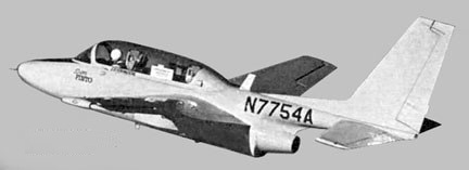
In June 1968 American Jet Industries Inc first flew the Super Pinto, a jet primary trainer or light strike aircraft developed from TT-1 Pinto built by Temco. Towards the end of the 1960s Aeronca undertook, in conjunction with American Jet Industries Inc., development of a light strike version of the Super Pinto, built originally as a jet primary trainer. Work was also done on five-seat executive version.
American Jet Industries Inc. was founded 1951, and became specialists in modification and repair of executive and transport aircraft, including large cargo types, and a successful program of Cessna turboprop conversions. In June 1968 first flew Super Pinto, a jet primary trainer or light strike aircraft developed from TT-1 Pinto built by Temco. Work was also done on five-seat executive version. Under a 1974 expansion program, production was concentrated in a facilities at Van Nuys Airport, California, building Hustler, a seven-seat business/utility monoplane with supercritical wing, conventional turboprop, and ‘standby’ turbofan in rear fuselage. First flight January 11,1978. Purchased Grumman American Aviation Corporation September 1978, being renamed Gulfstream American in 1979. Meantime, AJI renamed Gulfstream American Corporation of California, developing the Peregrine as a jet trainer and business aircraft. All programs stopped 1985.
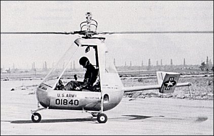
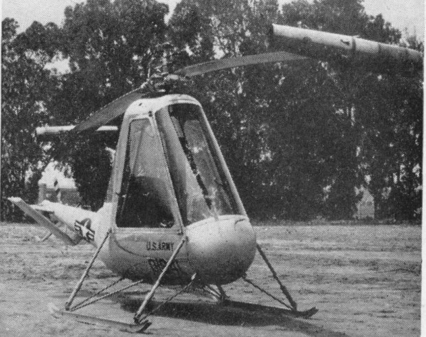
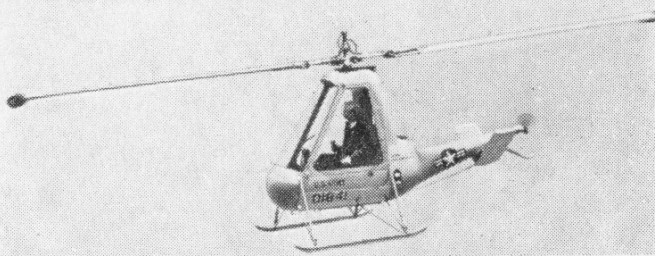
A 1950 Army specification called for a light, collapsible machine which could be used as both a light observation craft and as an air-droppable rescue vehicle for downed aircrew. American Helicopter responded with the Model XA-8 single-seat lightweight helicopter, design of which began in 1951 with the sponsorship of both the Army Transportation Corps and the USAF. American Helicopter was awarded a development contract in June 1951, and the first of a total of five XH-26s flew for the first time in June 1952.
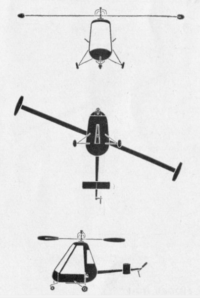
The XH-26 was designed from the beginning to be both collapsible and air-droppable and its construction and size reflected both requirements. Twelve feet long and six feet tall, the helicopter could be transported in a five foot by five foot by fourteen foot container and could be unpacked and assembled by two men in less than thirty minutes. The machine’s fuselage was built primarily of aluminum and fiberglass and featured a glazed, pyramid-shaped cockpit. The XH-26 was powered by two pulse-jet engines, one fixed to the tip of each main rotor blade, and could burn virtually any type of fuel. The Army and Air Force jointly evaluated the five XH-26 prototypes from 1952 to 1954 but neither service procured the type in quantity.
American Helicopter H-26 Engine: 2 x American Helicopter XPJ49-AH-3 7.5 in pulse-jets, 16.2kg Main rotor diameter: 8.23m / 27 ft Rotors: 2-blade, tip-powered main; 2-blade tail. Fuselage length: 3.73m Height: 1.88m Empty weight: 135kg MAUW: 1,040 lb. Max speed: 130km/h / 80 mph Cruising speed: 110km/h Service ceiling: 2280m Range: 160km / 105 miles at 70 mph with normal load Crew: 1