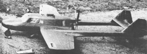
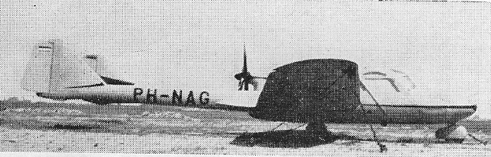
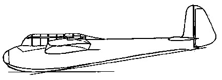
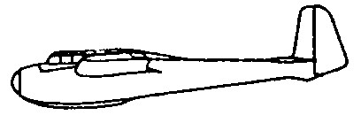
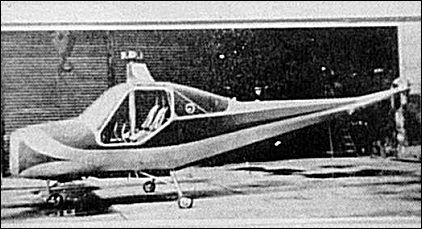
The DIFOGA 421 was built in secret during the war, but did not fly until the war was over. Its originator was Frits Diepen, Manager of Diepen’s Ford Garage (hence DIFOGA).
The aircraft was powered by a 98 hp Ford V-8 driving a four-blade wooden propeller.
In the 1940s, Benigno Diaz put together Cuba’s first homebuilt, assembled from plans in Popular Mechanics, with the help of a childhood friend, Roberto Gude. In 1938, Diaz and Gude used wood from fish crates and poplin from a fabric store to begin constructing the island’s first experimental aircraft. “It took us years,” Gude says. “We had to beg for every nut and bolt and piece of fabric and wood. Everything on that plane was improvised.”
The landing gear was crafted from automobile exhaust pipes. One friend, a pilot, donated a 65-hp Continental engine and the tires off a Piper J-3 Cub. After seven years, the airplane dubbed La Estrella Errante (Wandering Star) was finished. Diaz’s father was there for the 1945 maiden flight. He approached his son, put his arm around him, and said, “Benigno, are you sure you tightened all the bolts on that thing?” Diaz nodded. He climbed into the cockpit, turned the aircraft onto the grass field, and gave it power. Gaining speed, the little airplane bounced and lifted off. “It flew very well,” says Diaz, who still has a small model of his handiwork. “It was the first flight of the first homemade plane on the island.”
In 1999, the fate of that homebuilt airplane was unknown. Some say it was shipped to a military airfield in Cuba. “We heard it was there in mothballs, but we don’t know for sure. Someone else said the plane had been left outside on a tie-down and simply rotted.” Covered with house paint, its primitive construction “would not have stood up very long outside”.
After the Olympic games in Berlin in 1936 introduced gliding as an Olympic sport, plans were made to fly the 1940 Olympic championships with a standard design of sailplane to give each pilot the same chances. The FAI (Federation Aeronautique Internationale) duly announced a design competition for what was to be the Olympic sailplane. This specified a span of 15m (49ft 2.5 in), an empty weight of 160kg (353lb), a payload of 95kg (209lb) and a maximum speed of 200km/hour (124mph); only one material was to be used for construction throughout, air brakes were to be fitted but flaps or a retractable undercarriage were not allowed.
The competition was held at Sezze airfield in Italy between 20–26 February 1939 and was duly won by the Meise which had first flown earlier that year and which, like the other competing aircraft, was evaluated by six well known pilots from several other European countries.
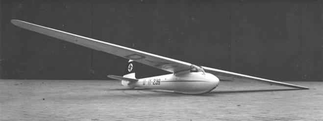
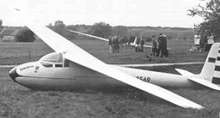
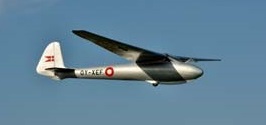
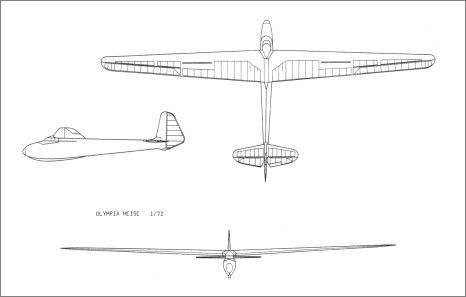
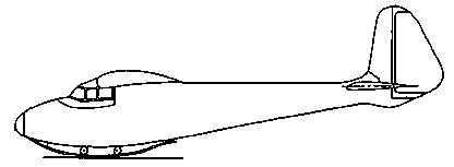
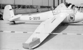
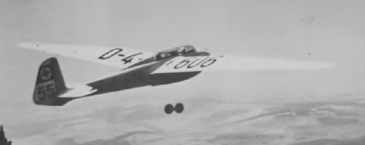
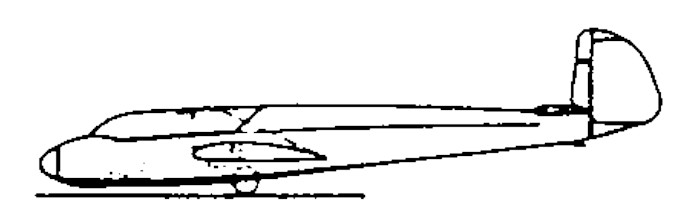
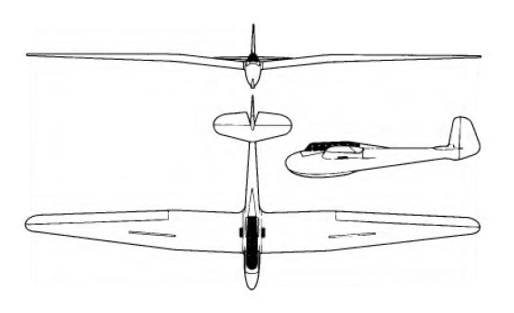
The Meise had been redesigned to fit into the new Olympic class specifications. The new ‘Olympia’ Meise had the prescribed wingspan of 15 m (49 ft 2 in), spoilers, but no flaps, and an undercarriage consisting of a skid and a non-retractable wheel. The pilot sat all-enclosed in an aerodynamically clean fuselage made of laminated wood and topped by an acrylic glass hood. The plane could be launched by winch as well by airplane. Its wood-and-fabric construction made it easy for flying clubs to maintain, to repair and even to build the gliders from kits. Approach control is by top and bottom Surface Schemmpp-Hirth type airbrakes. The original version used a takeoff dolly.
The Meise was in many respects a classic design with excellent flying qualities; its high cantilever wing was of wood and fabric construction and had DFS air brakes, while the fabric-covered wooden fuselage had a landing skid under the forward part, and the pilot sat under a detachable framed cockpit canopy in line with the wing leading edge.
When the Meise first flew it soon aroused interest in many countries in the few months before war broke out, and the German Aero Club supplied design details to a number of prospective customers.
Both the Meise as well as the Olympic class gained immediate enthusiastic support, and the 1940 Olympic gliding championship would probably have ended up as an all-Meise contest — if the Second World War had not intervened and the 1940 Olympics had not been cancelled.
Plans were distributed throughout the world for competing nations to produce their own Olympias. 626 Olympia Meises were built in Germany during the war by Flugzeugbau Ferdinand Schmetz Herzogenrath (601 built) and Flugzeugbau Schleicher (25). Most of the German production were among the 15,000 German gliders destroyed in 1945. 17 were also built at the time in Sweden.
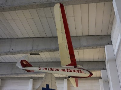
DFS 108 Olympia OH-OAA
Both the Meise as well as the Olympic class gained immediate enthusiastic support, and the 1940 Olympic gliding championship would probably have ended up as an all-Meise contest — if the Second World War had not intervened and the 1940 Olympics had not been cancelled.
626 Olympia Meises were built in Germany during the war by Flugzeugbau Ferdinand Schmetz Herzogenrath (601 built) and Flugzeugbau Schleicher (25). Most of the German production were among the 15,000 German gliders destroyed in 1945. 17 were also built at the time in Sweden.
The Meise, also sometimes known by the designation 108-70, set a pattern that lasted well into the postwar years, for it was built in France after the war as the Nord 2000. By November 1947, 100 Nord 2000 were ordered into production.
In Britain the design of the Olympia Meise was taken up by Chilton Aircraft Ltd., Elliotts of Newbury produced (as the EoN Type 5) the original skid version, and a modified version (Olypia 2B) with non-retractable main wheel.
The German drawings were not detailed and so entirely new drawings were made. Elliotts had been asked in 1945 by Chilton Aircraft Ltd to make one set of wings for the Chilton Olympia. An entirely new drawings were made by Chilton that merely retained the Meise Olympia’s aerodynamic shape. Otherwise it was a complete re-design and resulted in a stronger and heavier (+30 kg) aircraft.
To maintain employment at their factory, Elliotts refused to sell the wing jigs that they had made for the prototype. After building one prototype, which flew in 1946, the rights and drawings of the Chilton aircraft were taken up by Elliotts of Newbury (EoN) in the UK. Their first EoN Olympia flew in 1947. Later variations were produced by Elliotts into the late 1950s.
Production of the Olympia (originally called Type 5) started in 1946 as a batch of 100, and the first flight was made in January 1947. Elliotts and their design consultants Aviation & Engineering Products Ltd made improvements to the original design before starting production. Marks 1, 2 and 3 were produced, mainly distinguishable by the landing gear. The Mark 1 had only a skid whereas the Olympia 2 had a built-in main wheel. The Eon Olympia 3’s wheel was jettisonable after take off. The first batch of 100 was completed in 1947 but the market could not absorb such a large number, despite the low price of £425. Even by 1953, 40 of the first 100 Olympias were still unsold. Nevertheless, a second batch of 50 was built. Gliders from the second batch were still being offered for sale for £800 as late as 1957 in order to clear the stock, despite being below cost price.
After building three marks of the Olympia, another improved version, called the EoN Olympia 4 was produced in 1954. This is regarded as being sufficiently different from the original as being a new type. This type in turn led to a succession of variants.
The Olympia was also built after the war in Germany, in the Netherlands, in Spain, Switzerland (12), Hungary (35) with a further twenty modified as the Cinke, Australia (3), Austria and in Czechoslovakia as the Zlin Z-25 Šohaj, and Brazil (07).
The Vintage Sailplane Association has plans.
Structure: wood/fabric wings and tail, wood fuselage.
Variants: DFS Olympia Meise The original design for the 1940 Olympic gliding competition; built in large numbers during and after World War II, in Germany, Sweden, the Netherlands, Switzerland, Hungary, Austria and Brazil.
Chilton Olympia 2 A single prototype built in England, by Chilton Aircraft, in 1946.
Elliotts of Newbury EoN Olympia Further production in the UK after Elliotts acquired the rights to the design from Chilton. EoN Type 5 Olympia 1: Improved Olympia-Meise. Landing skid. EoN Type 5 Olympia 2: Fixed monowheel. EoN Type 5 Olympia 3: Jestisonable dolly wheels and skid. EoN Type 5 Olympia 4: New wing section, NACA 643618 at root, NACA 643421 at tip.
Nord 2000 Production in France post-war.
Zlin Z-25 Šohaj Production in Czechoslovakia post-war.
Cinke A modified version built in Hungary post-war.
Variations: Elliots of Newbury (EoN) EoN 10 Olympia Zlin Z-25 Šohaj
Specifications:
DFS Meise Wing span: 15.0 m / 49 ft 2.5 in Length: 7.27 m / 23 ft 10 in Wing area: 15.0 sq.m / 161.5 sq ft Wing section: Gottingen 549/676 Aspect ratio: 15.0 Empty weight: 160 kg / 353 lb Max weight: 255 kg / 562 lb Water ballast: None Max wing loading: 17.0 kg/sq.m / 3.48 lb/sq ft Max speed: 119 kt / 220 km/h Stalling speed: 29.5 kt / 55 km/h Min sinking speed: 0.67 m/sec / 2.2 ft/sec at 32 kt / 59 km/h Best glide ratio: 25.5 at 37 kt / 69 km/h
DFS Olympia Meise Length: 23.852 ft / 7.27 m Wingspan: 49.213 ft / 15.0 m Aspect ratio: 15.00 Airfoil: Go 549, root; 676, tip Wing area: 161.46 sq.ft / 15.0 sq.m Max take off weight: 661.5 lb / 300.0 kg Weight empty: 452.0 lb / 205.0 kg Max. weight carried: 209.5 lb / 95.0 kg Max. speed: 108 kts / 200 km/h Landing speed: 30 kts / 55 km/h Cruising speed: 35 kts / 65 km/h Wing loading: 4.1 lb/sq.ft / 20.0 kg/sq.m MinSink: 0.70 m/s / 2.3 fps / 1.36 kt at 37mph L/DMax: 25 66 kph/ 36 kt / 41 mph Glide ratio: 25.5:1 at 42.5mph Crew: 1
DFS Meise Wing span: 15.0 m / 49 ft 2.5 in Length: 7.27 m / 23 ft 10 in Wing area: 15.0 sq.m / 161.5 sq ft Wing section: Gottingen 549/676 Aspect ratio: 15.0 Empty weight: 160 kg / 353 lb Max weight: 255 kg / 562 lb Water ballast: None Max wing loading: 17.0 kg/sq.m / 3.48 lb/sq ft Max speed: 119 kt / 220 km/h Stalling speed: 29.5 kt / 55 km/h Min sinking speed: 0.67 m/sec / 2.2 ft/sec at 32 kt / 59 km/h Best glide ratio: 25.5 at 37 kt / 69 km/h
Olympia Meise 51 Wingspan: 15 m (49 ft 3 in) Wing area: 15 m2 (160 sq ft) Aspect ratio: 1.5 Length: 7.3 m (23 ft 11 in) Width: 0.58 m (1 ft 11 in) maximum fuselage width Empty weight: 165 kg (364 lb) equipped Max takeoff weight: 290 kg (639 lb) Never exceed speed: 220 km/h (137 mph; 119 kn) Aerotow speed: 100 km/h (62.1 mph; 54.0 kn) Winch launch speed: 80 km/h (49.7 mph; 43.2 kn) Maximum glide ratio: 25 at 70 km/h (43.5 mph; 37.8 kn) Rate of sink: 0.67 m/s (132 ft/min) at 60 km/h (37.3 mph; 32.4 kn) Wing loading: 17 kg/m2 (3.5 lb/sq ft) Crew: 1
EoN Olympia 2 Wingspan: 49 ft 3 in (15 m) Wing area: 160 sq ft (15 sq.m) Aspect ratio: 15 Airfoil: root:Göttingen 549 (mod.), tip:Göttingen 676 Length: 21 ft 8 in (6.61 m) Empty weight: 430 lb (195 kg) Max takeoff weight: 670 lb (304 kg) Stall speed: 31 mph; 27 kn (50 km/h) Never exceed speed: 129 mph; 112 kn (208 km/h) Rough air speed max: 128 km/h (79.5 mph; 69.1 kn) Aerotow speed: 100 km/h (62.1 mph; 54.0 kn) Winch launch speed: 100 km/h (62.1 mph; 54.0 kn) Maximum glide ratio: ~25 at 72.5 km/h (45.0 mph; 39.1 kn) Rate of sink: 132 ft/min (0.67 m/s) at 63 km/h (39.1 mph; 34.0 kn) Wing loading: 4.1 lb/sq ft (20 kg/m2) Crew: 1
The DFS Kranich (or Crane), which first flew in the autumn of 1935, was the real forerunner of this new breed of two-seater which could be used for competition flying and long distance soaring as well as dual-control training.
Designed by Ing Hans Jacobs and built by Ing Luck, the Kranich prototype was developed from an earlier Jacobs design, the Rhonsperber high performance single seater. After successful flight trials, the Kranich was put into production by Karl Schweyer A.G. at Mannheim, since the DFS did not manufacture aircraft of its own design except for prototypes, and altogether 400 Kranichs were built in Germany.
The type was also built under licence in Sweden, Poland, Yugoslavia, Czechoslovakia and Spain.
As late as 1952 Kranichs captured the first three places in the two-seater class in the World Gliding Championships held at Madrid and the type had previously set up more world records and many national ones. The two pilots sit in tandem under a long and narrow framed canopy with individual detachable sections, dual control being provided, and an unusual feature is a small transparent panel in each wing root to provide downward visibility for the instructor in the rear seat located behind the wing spar. Construction is of wood and fabric, the fuselage being of plywood. The mid-set gull wings were fitted with spoilers in the initial production version – use of these had been pioneered in the Rhonsperber – but the 1935 strengthened Kranich 2 was fitted with air brakes. Take-offs were made on a double wheel unit that was jettisoned when airborne, and there was a long ash skid under the forward fuselage for landing.
A Kranich 3 was used to flight test a special wing section for the Akaflieg Braunschweig SB-11, this wing section, of 1.5m span and 0.75m chord, being mounted on a steel tube framework on the tip of the nose in front of the cockpit, and having two large endplate surfaces on each side of it.
Kranch III
After the war 40 Kranich 3s were built by Focke-Wulf GmbH, the prototype of this series, registered D-3002, first flying on 28 May 1952. The Kranich 3 was different in several respects from the prewar versions; it had a new wing in the low-mid instead of mid position, with dihedral from the roots and straight taper instead of the gull wing with compound taper of prewar aircraft; aspect ratio was now 15.6 A longer forward fuselage was featured with the canopy top now flush with the fuselage top line; length was now 30ft 6.25in.
Kranich 3
In the early 1970s a powered version of this veteran design was produced by Eduard Schappert in Germany, who modified one of the Kranich 3s built postwar by Focke-Wulf GmbH to have a 35hp Fichtel & Sachs SA-2-440 engine mounted on a retractable pylon aft of the rear seat, and driving a two-blade tractor propeller. A fuel tank of glassfibre in the fuselage held 1.87 Imp gallons, and this variant was designated Kranich 3M. It had a maximum speed of 87mph with the engine on, a cruising speed of 62mph, a take-off run of 985ft and a maximum range of 74 miles.
Kranich Length : 25.262 ft / 7.7 m Wingspan : 59.055 ft / 18.0 m Crew : 2
Schweyer Kranich Wing span: 18.0 m (59 ft 0 in) Length: 7.7 m (25 ft 3 in) Wing area: 22.7 sq.m (244.4 sq.ft) Wing section: Gottingen 535 Aspect ratio: 14.3 Empty weight: 255 kg (562 lb) Max weight: 435 kg (959 lb) Water ballast: None Max wing loading: 19.16 kg/sq.m (3.92 lb/sq ft) Max speed: 116 kt (215 km/h) Stalling speed: 37.5 kt (70 km/h) Min sinking speed: 0.69 m/sec (2.3 ft/sec) Best glide ratio: 23.6
Kranich II Length : 25.262 ft / 7.7 m Wingspan: 59 ft 0.75 in / 18.0 m Wing area: 244.4 sq ft / 22.7sq.m Length: 25 ft 3.25 in Empty Weight: 562 lb / 290kg Max take off weight: 1025.3 lb / 465.0 kg Wing Loading: 20.5kg/sq.m Max. speed : 94 kts / 175 kph Crew: 2 L/DMax: 23.6 MinSink: 2.3 ft/sec / 0.69 m/s / 65 kph Aspect ratio: 14.27 Airfoil: Go 535
Kranch III Wing span: 59.383 ft / 18.1m Wing area: 21.06sq.m Length: 29.921 ft / 9.12 m Empty Weight: 330kg Max take off weight: 1146.6 lb / 520.0 kg Wing Load: 26.1kg/sq.m Max. speed: 100 kts / 185 kph MinSink: 0.70 m/s / 70 kph L/DMax: 30 80 kph Aspect ratio: 15.56 Airfoil: Go 549 Seats: 2
The aircraft department of a dockyard, opened in 1935, employing technicians from Pander. Built S.12 four-seat cabin monoplane, Scheldmusche light single-seat pusher biplane; best known for Scheldmeeuw single-seat flyingboat, which was built in all-metal and composite versions. It took over the designs of Pander and Zonen when that company went out of business in 1934. Schelde had taken over the aircraft construction department of the Pander furniture factory in The Hague at the end 1934. From 1939 made wings for Dornier Do 24 flying-boats, Aviolanda building the hulls. After 1945 began glider construction and Dakota conversion. In 1951 acquired license for production of Saab Safir. The aircraft construction department of the Royal Company De Schelde, joined Fokker on May lst, 1954.
A group of engineers and students at the Centra Tecnico de Aeronautica (CTA) of the Institute de Pesquisas e Desenvolvimento (IPD) under the leadership of Mr Guido Pessotti, produced the little 8m (26ft 3in) span Periquito II single-seater sailplane which had first flown in 1957 and of which three production examples were built.
This Brazilian high performance Standard Class single-seater was designed by a group of engineers and students at the Centra Tecnico de Aeronautica (CTA) of the Institute de Pesquisas e Desenvolvimento (IPD) under the leadership of Mr Guido Pessotti.
Also known as the PAR-6505 from the letters PAR signifying the IPD’s Departamento de Aeronaves, design work on the Urupema started in 1964 and construction of the prototype began the following year.
The cantilever shoulder wings have a forward sweep of 1° 22′ at the quarterchord line and are of wood/paper honeycomb/wood sandwich construction, as are the ailerons; DFS air brakes are fitted. The wooden semi-monocoque fuselage has a nose section of plywood/plastic foam/plywood sandwich construction. The tail unit is also of wood and honeycomb paper sandwich construction like the wings, and the tailplane is a one-piece all-moving surface with automatic antibalance tabs. There was a non-retractable BF Goodrich monowheel with brake mounted ahead of the eg on the prototype, but production aircraft have a retractable monowheel. The pilot sits in a semi-reclining seat under a long one-piece flush-fitting cockpit canopy, and optional ‘extras’ include a battery-operated electrical artifical horizon and a Bertea transceiver.
It first flew on 20 January 1968 and took part in that year’s World Gliding Championships at Leszno in Poland and in the 1970 World Championships at Marfa, Texas, where it was placed 22nd out of 40 competitors in the Standard class.
After flight tests were completed, production of a batch of 20 Urupemas began in January 1971 at the works of Embraer, the major Brazilian aircraft manufacturer, under the designation EMB-400.
6505 Urupema Wingspan: 15.0 m / 49 ft 2.5 in Length: 7.45 m / 24 ft 8.5 in Height: 1.52 m / 4 ft 11.5 in Wing area: 12.0 sq.m / 129.2 sqft Aspect ratio: 18.75 Wing section: Wortmann FX-05-171/121 Empty weight: 230 kg / 507 lb Max weight: 310 kg / 683 lb Water ballast: None Max wing loading 25.83 kg/sq.m / 5.29 lb/sq ft Max speed: 159 mph / 138 kt / 255 km/h (in smooth air) Max rough air speed: 86 kt / 160 km/h Stalling speed: 33 kt / 61 km/h Min sinking speed: 2.1 ft/sec / 0.66 m/sec at 48 mph / 42 kt / 78 km/h Best glide ratio: 36:1 at 58.5 mph / 51 kt / 95 km/h
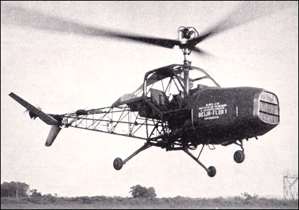
The Beija-Flor is a two-seat helicopter, which was designed in 1956 and built to the initial design of Professor Heinrich Focke at the Centre Tecnico de Aeronautica at the military research and overhaul centre at Sao Jose dos Campos. The forward-located 225hp Continental E225 engine drives the main and tail rotors through a centrifugal clutch and a David Brown lorry worm and wheel. The main rotor incorporates a mechanical-hydraulic automatic stabilising mechanism which reduces flapping to zero in the pitch direction. Roll control is provided by normal “swash-plate” movement. Pitch and yaw control is provided by the unique V-type intermeshing twin tail rotor which also serves to incline the main rotor plane for forward flight. An open structure tubular steel tail boom carried a pair of tail surfaces and a small tail rotor. The material used in the construction of the helicopter is almost entirely of national origin and this has unavoidably led to an excessive weight.
The Beija-Flor is the first helicopter to be designed, built and flown in Brazil and was first flown on 1 January 1959 by Colonel Aldo Vieira da Rosa, a Brazilian Air Force officer and director of the Instituto de Pesquisas e Desenvolvimento da Aeronautica. The first flights concentrated on a preliminary assessment of control and stability. It was damaged in an accident and it is thought that further work on the Beija Flor was then abandoned.
Beija-Flor BF-1 Main rotor diameter: 9.0m Overall length: 8.43m Height over rotor hub: 3.15m Weight loaded: 950kg Max speed at sea level: 150km/h Cruise speed for max range: 130km/h Cruise speed (75% power): 140km/h Max rate of climb: 370m/min Service ceiling: 3500m Max ceiling: 3750m Hover ceiling with ground effect: 2700m Hover ceiling without ground effect: 1400m Range at best cruise speed: 270km Max endurance: 3h
Brazil The aircraft department of the Instituto de Pesquisas e Desenvolvimento (IPD). From 1970 concentrated entirely on research, all design and development being handed over to Embraer. Between 1959 and 1964 it developed prototypes of the Beija-Flor two-seat light helicopter, designed especially for Brazilian conditions by Prof. Heinrich Focke, formerly of Focke-Achgelis.