Dominion Skytrader 800 / Skytrader Corporation UV-23A Scout

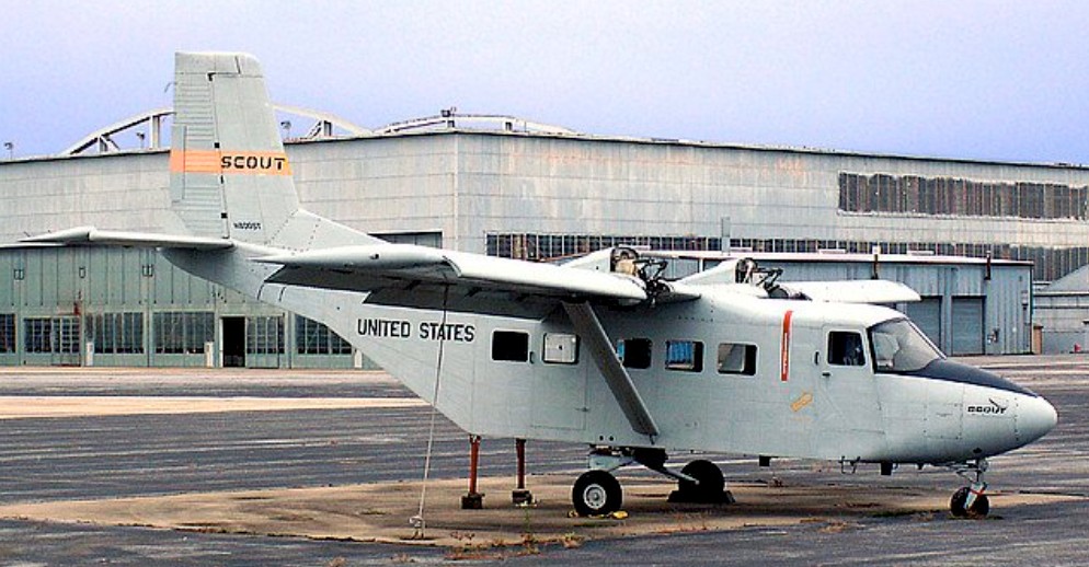
The Skytrader was a conventional high-wing, strut-braced monoplane with fixed tricycle undercarriage designed in Renton, Washington, by laid-off Boeing engineers in 1972. The design was optimised for easy freight handling and featured a fuselage of rectangular cross-section with large loading doors to the side and a loading ramp at the rear. The aircraft’s tail unit was angled upwards from the rear fuselage to facilitate loading operations beneath it, and the main undercarriage was fitted in sponsons on the fuselage sides so as not to intrude into the internal cargo volume. Passenger, freight, executive transport, and water-bomber versions were projected.

Work on the aircraft commenced in 1972 and the prototype (N800ST) flew on 21 April 1975. Marketing the aircraft proved difficult, however, and despite a flurry of initial interest, by 1977, only two firm orders are known to have been placed. Two years later, the bank that had been financing the project collapsed and Dominion went bankrupt. The prototype and the program were purchased the following year by Grant MacCoon, and over the next few years were bought and sold by a number of entities, finally becoming the property of a new firm, Skytrader Corporation, in 1984. Skytrader Corporation was founded in 1984 to develop the Skytrader 800 but with some changes.

Skytrader proposed a revised version of the original design as the Skytrader ST1700 or Conestoga. Originally powered by IO-720s, it was planned to fit Thunder TE495-TC700 liquid-cooled V-8s, but it was then planned with Turbomeca Astazou turboprops. This had a stretched cabin, T-tail, redesigned nose, wings, and landing gear, and was to be turboprop powered. A scaled-down version was to be offered as the ST1400 Commuterliner. Apart from passenger and freight versions, dedicated military versions were also proposed as the Evader, carrying 26 troops, or the smaller Scout. This would have been able to carry 12-15 troops and provision was made for armament in the form of 2.75 in air-to-ground rockets. In 1987, Skytrader announced a deal with Mitsui that would provide $20.5 million to fund FAA certification of the ST1700, and initial production of the Scout.

The Mitsui money never appeared, and the following year, Skytrader made co-production deals with the government of the Philippines and Samsung, but these did not eventuate either. The final chapter in the Skytrader’s development was the entry of the Scout in a US Army competition for an intelligence gathering plane. During the late 1980s, the U.S. Southern Command became interested in acquiring a reconnaissance plane which would do well in the rugged terrain and with the clandestine operations that the command was executing at the time. A contest, named Grizzly Hunter, was opened for interested contractors to enter candidate airplanes for consideration.

The Scout was entered as a joint project between Skytrader and McDonnell Douglas Helicopter, and was selected as the winning design, receiving the designation UV-23. Revisions to the original Scout design included blown wings and new propellers and gearboxes to significantly reduce the aircraft’s IR and noise signatures. The Skytrader 800 prototype was re-engined at this point, and flew with Turbomeca Astazou XIV turboprops. Before any production of the UV-23 could be undertaken, however, Grizzly Hunter was cancelled and replaced by a different requirement which was won by the RC-7. With the Army order falling through, Skytrader declared bankruptcy in April 1989 with intentions on continuing operations and was liquidated in August 1989.

As of 2007, the prototype lay derelict, with engines stripped, at Washington County Regional Airport, in Hagerstown, Maryland.

Gallery

Skytrader 800
Engines: 2 × Lycoming IO-720-B1A, 400 hp (298 kW)
Wingspan: 55 ft 0 in (16.76 m)
Wing area: 385 sq.ft (35.77 sq.m)
Length: 41 ft 0 in (12.50 m)
Height: 18 ft 10¾ in (5.76 m)
Empty weight: 4,950 lb (2,245 kg)
Gross weight: 8,500 lb (3,855 kg)
Maximum speed: 210 mph (338 km/h)
Cruise speed: 150 mph (241 km/h)
Range: 1,430 miles (2,300 km)
Service ceiling: 17,500 ft (5,355 m)
Rate of climb: 1,600 ft/min (8.1 m/s)
Crew: Two pilots
Capacity: 12 passengers

Doman LZ-5 / YH-31 / D-10          

The LZ-5 was similar to the LZ-4 but used a 400hp supercharged Lycoming 580-D engine, and had numerous detail changes. The measurements and layout of this production model very closely resemble those of the hand-made LZ-4. The 8-cylinder supercharged engine is placed beneath the pilot’s compartment; the crankshaft is inclined at an angle of 32degs and drive engagement to the rotor is through a fluid coupling. The front cabin is big enough to take two pilots; the main cabin has room for six passengers with luggage, or four stretchers or cargo over an area of 3.7 square metres. The first example first flew on 27 April 1953. With hingeless rotor unit and hydraulic rotor control system, the prototype received C.A.A. certification for passenger carrying in 1953.

Doman gained a contract from the U.S. Army to supply two aircraft designated YH-31. These were evaluated following delivery in late 1953 (serials 52-5779 and -5780) but it was felt that the possible maintenance problems of the complex rotor system would cause problems with field maintenance. Consequently, the two aircraft were retired in 1958 following a period of use as executive transports in the Washington, DC area until their 1958 withdrawal from the Army inventory. Doman also designed a small two-seat helicopter, the D-10, to an Army requirement. This would have been powered by an Allison 250 turbine but was not built.

Doman actually completed two more development machines in addition to the pair of YH-31s (N94561 and N812). The third aircraft was modified into a new variant – the D-10B – which had a turbocharged Lycoming HIO-720-A1A engine and minor changes and was the subject of a co-production agreement with Fleet in Canada. N812 became CF-IBG-X.

For the Fleet licence agreement one LZ-5 prototype was demonstrated in Canadian markings.

A number of deals and production relationships were subsequently established by Doman in an effort to get the LZ.5 into production. Hiller were licenced to build the military version. Doman also entered into an arrangement with Ambrosini in Italy for them to market the D-10B and for production of 20 airframes to be carried out by Aeronautica Sicula at Palermo in Sicily with final assembly at Doman’s factory in Danbury, Connecticut. A plan was also devised for Aeronautica Sicula to fit a D-10B with a Turbomeca Astazou turbine. The agreement with the Italians collapsed and a new company was subsequently established as Caribe Doman in Puerto Rico during 1966.

Unfortunately, the LZ-5 was obsolete by this time as more modern turbine-powered helicopters flooded onto the market. A further company, Berlin-Doman was formed and a new project launched as the BD-19 but this was also stillborn and the Doman helicopters finally vanished into obscurity.

With its 7 ft (2.13 m) wide doors removed on both sides the helicopter showed in mid-1956 its capability of lifting bulky cargo without slings by transporting a 1,900 lb (862 kg) cabriolet Volkswagen.

Only three LZ-5s were built.

LZ-5
Engine: 1 x Lycoming SO-580-D, 400hp
Rotor diameter: 48 ft / 14.64m
Type of rotors: 4-blade main; 3-blade tail.
Fuselage Length: 37 ft. 10 in / 11.57m
Height: 3.12m
Gross weight: 5,000 lb / 2363kg
Empty weight: 1297kg
Maximum speed: 110 m.p.h./ 169km/h
Cruising speed: 138km/h
Rate of climb: 396m/min
Absolute ceiling: 18,000 ft / 5490m
Typical range: 245 miles at 86 m.p.h. with full load.
Number of seats: 8

Doman LZ-4

After the LZ-2A Pelican, Doman’s system was designed into a larger helicopter that was seen as a viable commercial production machine. The LZ-4A had a large fuselage with three rows of double seats in the main cabin and a two-crew flight deck in front. Large folding doors provided access for loading bulky cargo into the main compartment. The tail boom was conventional with a cranked-up rear section mounting a tail rotor, and the LZ-4A sat on a four-leg undercarriage with trailing link dampers. A 400hp Lycoming SO-590-B engine was positioned in the lower nose, driving the four-blade rotor via a flexible transmission. Following its first flight in November 1950, and subsequent testing, Doman moved on to the improved LZ-5 and transferred the LZ-4A (N74147) to Curtiss Wright, where it was given the designation of CW-40, as a test vehicle. The LZ-4’s first flew in November 1950.

LZ-4
Number of seats: 8
Engine: 1 x Lycoming SO-590-B, 400hp
Rotor diameter: 14.64m
Length: 11.7m
Height: 3.41m
Gross weight: 2165kg
Empty weight: 1343kg
Cruising speed: 125km/h
Rate of climb: 244m/min
Absolute ceiling: 4880m
Range: 336km

Doman LZ-1A

Doman Helicopters Inc. was founded in 1945 for the purpose of exploiting patents taken out by Gliden S. Doman, who during World War II had worked with Sikorsky. The patents related to a new system for controlling and attaching helicopter blades.
These included a new hub system which was essentially similar to the mechanism used on a variable pitch propeller. The rotor system also incorporated a gimbal mounting to provide the necessary tilting of the rotor disc and rotating it by means of a unique constant-velocity driving system. No blade-flapping hinges, drag hinges or hinge dampers were required and bearings subject to centrifugal loads with oscillating motion are reduced to a minimum. The Doman rotor incorporates the speed reduction gearing as an integral part of the rotor assembly. All moving parts are contained within a common housing which precludes damage from weather or foreign matter.
Doman’s theories were tested initially by installing an experimental system on a USAF Sikorsky R-6 in 1947. The rotor had four blades, and though their length was increased from 11.58 to 12.2 metres, this resulted in improved hovering ability and did not lower the top speed.
The helicopter was known as the Doman LZ-1A and it started flight tests in early 1950 with good results. The first flights took place early in 1950 and it should be noted that during one experimental flight this rotorcraft flew for forty minutes without the pilot needing even once to touch the cyclic pitch control.
It was followed by the larger LZ-2A Pelican.

LZ-1A
Engine: 1 x Franklin 0-405-9, 245hp
Rotor diameter: 12.2m
Length: 10.34m
Height: 3.35m
Gross weight: 1350kg
Empty weight: 871kg
Cruising speed: 136km/h
Rate of climb: 275m/min
Range: 640km
Number of seats: 2

Doman / Doman-Frasier Helicopters Inc      

Glidden J. Doman
Doman-Frasier Helicopters Inc
Berlin-Doman Helicopters

Founded in 1945 by Glidden J. Doman at Danbury, New York, to construct rotorcraft with hingeless rotorblades and totally enclosed self-lubricating hub. Produced LZ-1 a, LZ- 2a Pelican, LZ-4, LZ-5 ,and a developed version, DB-1 OB, in 1953. At one time known as Doman-Frasier Helicopters Inc. Doman H-31 of 1952 was license-built by Hiller Aircraft Company Inc. Operations transferred to Puerto Rico, with continued production of DB-10B and name changed in 1967 to Berlin-Doman Helicopters, recognizing interests of Chairman Dr. Don R. Berlin.

Doak 16 / VZ-4

Company president, Edmond R. Doak, had experimented with ducted fan and various other air moving principles since 1935. He first proposed a VTOL aircraft using the tilt duct principle to the military as early as 1950. The Army issued the contract to Doak on April 10, 1956. The U.S. Army Transportation Research and Engineering Command purchased a single Doak 16. The Model 16 made its first flight in February 1958 and the single prototype was put through extensive pre-delivery flight testing and was not officially accepted by the Army until September 1959. Upon acceptance the craft, which had already been allocated the serial number 56-9642, was given the designation VZ-4.

Early 1958

Doak Model 16 was the first VTOL aircraft to demonstrate the tilt duct concept. It was built by the Doak Aircraft Company of Torrance, CA.
The fuselage was constructed of welded steel tubing covered by moulded fiberglass skin from the cockpit forward, while the wings and tail were metal-skinned. The aircraft was designed to accommodate a pilot and observer sitting in tandem, though as far as can be determined the observer’s seat was never actually installed in the prototype.
With a mid-wing, conventional tail, and fixed tricycle landing gear, a single 1000shp Lycoming YT53-L-1 turbine mounted in the fuselage just aft of the cockpit drove two ducted-fan airscrews, one fixed within each rotating wingtip fan assembly. The fans were set in the vertical position for takeoff and landing, and were rotated into the horizontal plane for normal forward flight. Some additional directional stability was provided by routing the turbine exhaust through a set of hinged louvers mounted in the aircraft’s tail.
The cantilever wing and tail unit were of all metal construction. To save development costs, Doak incorporated numerous off the shelf items in the design, such as the landing gear from a Cessna 182, seats from a F-51, duct actuators from T-33 electric flap motors, and the rudder mechanism from an earlier Doak aircraft.

The design empty weight was 900kg with a design gross vertical take-off weight of 1170kg. These grew to 1037kg and 1443kg during the life of the program. To keep weight down, the original specification called for the aircraft fuselage to remain uncovered. However, it subsequently was felt that this would severely limit being able to obtain any meaningful forward speed data, and that the added weight would allow for much more valuable data to be collected.

The wingtip-mounted ducts were five feet in diameter with a four foot inside diameter. Their construction was of aluminum alloy with a fiberglass leading edge section. Eight fixed pitch fiberglass fan blades turned at a maximum fan speed of 4800 rpm. Ahead of the fan in the forward part of the duct were fourteen fiberglass variable inlet guide vanes. The vane angle varied during hover to modulate the thrust produced by the duct, and thus to obtain roll control. The prop was set back two feet from the front of the duct to prevent airflow separation. Nine stainless steel stator blades located aft of the fan straightened the air flow as it exited the duct.
The ducts rotated through 92 degrees, pointing horizontal for forward flight, and pivoting to 2 degrees aft of vertical during hover. The ducts rotated past vertical to compensate for the thrust from the jet exhaust. A switch on the control column initiated the duct rotation. To power the fans, drive shafts traveled through the wing quarter chord. Doak-designed flexible couplings compensated for misalignment and wing flexing.

A Lycoming T-53-L-1 turboshaft engine located in the fuselage just below the wing root provided power. It produced 825hp (some sources stated 840hp). A “T” box on the engine transmitted power to the ducts using a four-inch tubular aluminum shaft and two smaller steel shafts of 3.8cm each.
Flight controls consisted of standard stick and rudder. An electrical and mechanical interlock system controlled all functions for both hovering and forward flight. There were no other cockpit controls. In hover, a cruciform shaped vane in the tail pipe at the rear of the fuselage controlled pitch and yaw by deflecting the engine exhaust. Rotating the inlet guide vanes in the ducts provided roll control by restricting airflow. As the ducts rotated from vertical to horizontal, a mechanical control system gradually phased out control of the inlet guide vanes and left them aligned with the duct airflow. There was no artificial damping or power boost. Doak looked down on any type of automatic stabilization system, feeling that the aircraft should be a satisfactory flying machine without any such equipment. Careful selection of the duct location allowed the fuselage to remain level throughout the transition.
Ground testing began at Torrance Municipal Airport during February 1958. Tests consisted of 32 hours in a test stand, and 18 hours of tethered hovering and taxi tests. The first free hovering flight was performed on February 25 1958. Initial Doak testing at Torrance was completed in June 1958 and was followed by a complete tear down inspection. The aircraft then was transferred to Edwards AFB in October 1958. At Edwards, it performed 50 hours of tests, including transitions at altitudes as great as 1830m. James B. Reichert completed the first conversions in 1959. Following these tests, the Army accepted the Doak 16 in September 1959 and transferred it to NASA Langley for further tests.
In 1961 Douglas Aircraft Co. purchased the design rights and test data on the VZ 4. Douglas liked the aircraft and had some ideas for improving it, primarily by installing a larger engine and making numerous structural improvements. They made an unsolicited proposal to the Army in 1961, but could not sell their ideas. The Doak 16 remained at NASA Langley until August of 1972. Eventually it was transferred to the U.S. Army Transportation Command Museum at Fort Eustis, VA, near Newport News, where it is on display.

VZ-4
Engine: 1 x Lycoming YT53, 625kW / 800 hp
Wingspan: 7.77m
Length: 9.75m
Height: 3m
Wing area: 8.73sq.m
Empty weight: 900-1037 kg
Max take-off weight: 1170-1443kg
Max speed: 370km/h est.
Rate of climb SL: 30m/s
Hover ceiling: 1830m
Endurance: 1 hr
Range: 370km
Crew: 2

Doak Aircraft Co Inc

Incorporated in 1940 in Los Angeles, California, developing the Model 16 VZ-4Da, with ducted propellers rotating at wingtips, under contract to the U.S. Army Transportation Research and Engineering Command, 1958. This was transferred to NASA for further evaluation. Doak sold out to Douglas Aircraft Company in early 1960s. Doak finally closed its doors early in 1961.

Dmitriev X-14d

Dmitriev’s airplane is neither an outgrowth of a hang glider nor an enclosed cockpit design. First, it’s in-credibly tiny only 10.9 feet long, 16.4 feet in wingspan, and four feet high at the tail. Its wing area is only 18.9 square feet. It’s light, even by ultra¬light standards 110 pounds, as Dmitriev had it outfitted in July 1992.
But Dmitrievs diminutive craft is most striking in its use of big airplane features to get maximum performance from its flying surfaces. Its wing has airliner style flaps and leading edge slats, giving it more lift and thereby reducing takeoff and landing speeds. A slight but noticeable forward sweep to the wing makes it more controllable at low speeds. And extra joints in the elevators and rudder increase the effectiveness of their small surfaces.
It all comes apart and folds up for storage. Each wing section detaches and then folds in half, the tail group comes off and folds, and even the aluminum tubes connecting the tail section are designed to telescope. The result is a package you can store in a closet, rightfully earning it the nickname of “suitcase ultralight.”
The X 14d’s leading edge slat and triple slotted flaps are controlled by a single mechanical lever on the pilot’s left side, the flaps and slats extend and retract in unison. Fully extended, they greatly magnify the lift of the X 14d’s tiny wings and reduce the speed needed to get airborne. They also allow a slower landing. On the down side, flaps also increase drag, so they’re retracted into the wing structure for cruising.
Similar slotted surfaces are evident at the tail, but their functions are different. Horizontal elevators at the rear deflect the air passing over them, controlling the air¬plane’s pitch axis; Dmitriev added joints in the elevators to increase their effectiveness without increasing their size. The upright rudder, which controls yaw axis gets a similar segmented treatment.
Aiding the X 14d’s ailerons are spoilers, or short slats, that rise from the upper surface of the wing just forward of the ailerons. In Dmitriev’s design, each spoiler ex¬tends automatically when the aileron behind it is fully deflected, enhancing roll control.at low speed.
Primary flight functions, including throttle setting, elevator position, and aileron position, are con¬trolled from a hand hewn control yoke. Seated forward of the wing, With legs nearly straight ahead the pilot hss an unimpeded view, though his ears are just inches from the engine din.
Dmitriev is hardly a test pilot, and he said his longest flight in Kirghizia lasted just 8.5 minutes, when his engine quit. He says the highest he has flown it is 350 feet much too close to the cold, hard ground for testing a plane’s behavior in steep turns or stalls.

Engine: 24 hp.
Length: 10.9 ft.
Wingspan: 16.4 ft.
Height: 4 ft.
Wing area: 18.9 sq.ft.
Empty wt: 110 lbs.