EAA A-1 Biplane

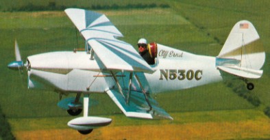
In 1955, the EAA decided to develop a single-seat sport biplane as a service to its members. The prototype was built as a classroom project by students of St.Rita’s High School in Chicago. It flew for the first time on 10 June 1960. The E.A.A. Biplane was designed in response to many requests from members of the American Experimental Aircraft Association for a single seater sports biplane of simple yet rugged construction. The fuselage consists of a welded chrome-moly steel tube frame, to which are fitted plywood formers and wooden stringers, the whole being fabric covered apart from the aluminium coaming panels. Both upper and lower wings have solid spruce spars and built-up wooden ribs, and are internally and externally wire braced. The leading edge to the front spar is aluminium covered, the remainder being fabric covered. Interplane and centre section struts are made of streamline steel tube. A 9.5 Imp. gallon fuel tank is fitted behind the firewall. The empennage, like the fuselage, is built up of welded steel tube and is fabric covered and externally braced. The ailerons which are installed on the lower wing only, are operated by means of push rods, while the elevator and rudder are cable operated. The main undercarriage is built up of steel tube with bungee cords for shock absorption.

EAA Biplane by Herb Dyer

Gallery

Engine: Continental C-85, 85 hp.
Wing span: 20 ft 0 in (6.1 m).
Wing Area: 108 sq. ft.
Wing Loading: 9.4 lb./sq.ft.
Length: 17 ft 0 in (5.18 m).
Height: 6 ft 0 in (1.83 m).
Max TO wt: 1150 lb (522 kg).
Empty Wt. 640 lb.
Fuel capacity 12 USG.
Max level speed: 125 mph (201 kph).
Stall mph 55.
Climb rate 800fpm.
Takeoff run 500 ft.
Landing roll 550 ft.
Range 200 sm.

Dyna Soar Standard          

The Dyna Soar Standard is a standard Rogallo which features a “Dyna-pin” which consists of a hitch pin, stainless steel spring, and quick release pin for quick assembly of the leading edges to the cross spar. The flying wires can be interchanged to move the control bar from seat to prone to supine position. Wing stabiliser minimise leading edge distortion at higher loading. The keel reflex, standard n all models, improves the L/D and compliments the wing stabilisers for a more stable flight.

The airframe is made from 6063-T832 1.5 in x 0.058 anodised alumingium tubing, and the rigging is aircraft quality 3/32in 7×7 plastic coated. All nuts and bolts are aircraft quality, and tangs are stainless. The sail is Howe and Bainbridge 3.8 oz stabilised dacron. All seams are double zig zag stiched and stress points are reinforced.

It can be adapted for towing.

15×15
Leading edge: 15 ft 6 in
Keel length: 15 ft 6 in
Wing span: 20 ft 6 in
Wing area: 155 sq,ft
Aspect ratio: 3.75
Nose angle: 83˚
Sail billow: 3.5˚
Weight: 34 lb
Pilot weight: 90-140 lb
Takeoff speed: 15 mph
Stall speed: 14 mph
Max speed: 21 mph
Best glide ratio (L/D): 5:1
Best L/D speed: 20 mph
Min sink: 450 fpm

15×17
Leading edge: 17 ft 6 in
Keel length: 17 ft 6 in
Wing span: 23 ft 2.5 in
Wing area: 210 sq,ft
Aspect ratio: 3.75
Nose angle: 83˚
Sail billow: 3.5˚
Weight: 41 lb
Pilot weight: 150-200 lb
Takeoff speed: 15 mph
Stall speed: 14 mph
Max speed: 21 mph
Best glide ratio (L/D): 5:1
Best L/D speed: 20 mph
Min sink: 450 fpm

15×18
Leading edge: 18 ft 6 in
Keel length: 18 ft 6 in
Wing span: 24 ft 6 in
Wing area: 240 sq,ft
Aspect ratio: 3.75
Nose angle: 83˚
Sail billow: 3.5˚
Weight: 45 lb
Pilot weight: 170-240 lb
Takeoff speed: 15 mph
Stall speed: 14 mph
Max speed: 21 mph
Best glide ratio (L/D): 5:1
Best L/D speed: 20 mph
Min sink: 450 fpm

Dyna-Cam / Axial Vector Engine Corporation Dyna-Cam / Herrmann Group Dyna-Cam

The Dyna-Cam engine originally came from a design by the Blazer brothers, who worked for Studebaker in 1916. They sold the rights to Karl Herrmann, Studebaker’s head of engineering, who developed the concept over many years, eventually taking out US patent 2237989 in 1941. It has 6 double-ended pistons working in 6 cylinders, and its 12 combustion chambers are fired every revolution of the drive shaft. The pistons drive a sine-shaped cam, as opposed to a swashplate or wobble-plate, hence its name.
In 1961, at the age of 80, Herrmann sold the rights to one of his employees, Edward Palmer, who set up the Dyna-Cam Engine Corp. along with son Dennis. Edward’s son Dennis and daughter Pat then helped get the engine installed in a Piper Arrow. The engine was flown for about 700 hours in the Piper Arrow from 1987 through 1991. Their longest engine ran for nearly 4000 hours before overhaul. Dyna-Cam opened an R & D facility in around 1993 and won many various awards from NASA, US Navy, the US Marine Corps, California Energy Commission, Air Quality Management District, and Los Angeles Regional Technology Alliance for different variations of the same Dyna-Cam Engine. About 40 prototype engines were built by the Herrmann Group and another 25 built by the Dyna-Cam Group since they acquired the engine and opened their shop. A new patent was granted to Dennis Palmer and Edward Palmer first in 1985 and then several more around 2000 to Dennis Palmer. In 2003 the assets of the Dyna-Cam Engine Corp were acquired by first Aero-Marine Corp. who changed their name to Axial Vector Engine Corporation. Axial Vector then totally re-designed the cam engine. Axial Vector’s new engine suffers from problems, including piezoelectric valves and ignition, ceramic cylinder liners with no piston rings, and a variety of other advanced features. It has almost no similarity to the original Herrmann and Dyna-Cam Engine since the Dyna-Cam Engine used conventional valves, piston rings, accessories, had no unproven ceramic materials and actually flew in a Piper Arrow and also powered a 20-foot (6.1 m) Eliminator Ski Boat for over four years.

Cycle: 4 stroke
No cylinders: 12 bore
Cooling: Liquid
Ignition: Electronic
Reduction: Direct
Weight: 150 kg
Max pwr: 220 hp at 1800 rpm
Max torque: 400 at 1200 rpm
Fuel consumption: 170 G/hp/hr

Dyke Delta JD II

The JD-2 was developed from the JD-1 flying-wing type. The JD-1 had fabric covered wings.

John Dyke wanted a high-speed airplane with folding wings that would be compact enough to tow home for garage storage — thus the unique delta design. The basic fuselage skeleton, vertical stabalizer and wing spars are of welded steel tube. The wings have an all-metal frame and have been tried with either fiberglass or aluminum covering. Virtually the entire planform surface of the Delta provides lift at cruise speeds. A 180-hp Lycoming provides the power. First flew 1966

Gallery

Engine: Lycoming O-360, 180 hp.
HP range: 160-200.
Gross Wt. 1950 lb
Empty Wt. 1080 lb
Fuel capacity 47 USG.
Wingspan: 22.2 ft.
Length: 19 ft.
Height: 5.5 ft.
Wing area: 178 sq.ft.
Top 210 mph.
Cruise mph 180.
Stall mph — no stall.
Climb rate 2000 fpm.
Takeoff run 700 ft.
Landing roll 1000 ft.
Range 633 sm.
Service ceiling: 14,500 ft.
Seats: 4.
Retractable nose wheel.

Dyke

1995-6: 2840 Old Yellow Springs Rd, Fairborn, OH 45324, USA.
Dyke Delta JD-2 first flew 1966 as unusual four-seat deltawing homebuilt, still offered in plans and component forms for amateur construction. JD-2 developed from previous JD-1 flying-wing type.

Durand XD-85

This was a 2-seat pusher designed and built by Mr. William H. Durand and the aircraft first flew during the Summer of 1948. The all-metal XD-85 was powered by an 85hp Continental C85-12J engine. The aircraft reportedly sustained wing damage in a hangar incident and was not rebuilt. Further development was halted, a fate not uncommon to many other (light) aircraft projects of the immediate post-war years.

Duruble Roland Duruble 2 / RD 02r Edelweisse

Conceived primitively in 1945 of wood, and the construction beginning in 1946, there were disappointments with the Caurite glue. The Office Véritas informed the builders that the plane could not be accepted.
With thoughts of a metallic prototype, the goal was to show that one with 65 cvs. Several years of study and the first drawings done, the framework began at Bessonneau until 1956. The plane was transported at Legrand, where the prototype was finished towards the end of 1961.
The assembly and completion were achieved at the Boos airfield.
July 7, 1962, Edelweiss first flew. Testing by the CNRA was completed June 24. CNRA n° 270952 was delivered August 19, 1963, partner to the file n° 341 of August 23, 1963.
A two-seater, all metal plane, with a Walter-Mikron 4-III motor of 65 hp at 2600 rpm, with retractable tricycle undercarriage.
The Edelweisse was presented to the gathering of the amateur constructors at Rouen-Boos the 16, 17 and 18 August 1963 and made a sensation.
On February 21, 1981, a motor breakdown led Roland Duruble to fit a Revmaster 2100D n°s 2496 of 75 hp, and a twin-bladed metallic constant speed Maloof propeller.
The prop was replaced with a twin-bladed in wood and Revmaster reduced performance to 65 hp at 3200 rpm, although TBO became 1000 hrs instead of 800. Climb rate was noted at + 1,5 m/ses to 11500 ft. The
By October 8, 1984 with 947 hs 25 min TT. the craft wass sold to M. Jacques Plumet. The reported flight time on October 23, 1993 was 1097 hs 39min.