Founded by C R. (later Sir Richard) Fairey, initially to build 12 Short 827 seaplanes. Leased premises at Hayes, Middlesex, replaced by new factory 1917-1918. Became a public company March 5,1929 and the following year opened new airfield at Harmondsworth, later requisitioned and incorporated in site for London’s Heathrow Airport. Reorganized as holding company The Fairey Company Ltd. March 31,1959, aircraft manufacturing subsidiary becoming Fairey Aviation Ltd. and the Stockport plant Fairey Engineering Ltd. Fairey Aviation Ltd. merged with Westland Aircraft Ltd. in 1960. Britten-Norman (Bembridge) Ltd. acquired 1972. Fairey group into liquidation 1977; engineering activities acquired by National Enterprise Board; Britten-Norman operated by liquidator pending sale.
Company designs included F.2 twin-engined biplane fighter; camber-changing trailing-edge flaps introduced on Hamble Baby. Fairey III series introduced 1917; final model IIIF entered production 1926 and declared obsolete 1940. Fairey Hendon (1930) was the first British cantilever monoplane heavy bomber; Long-range Monoplane captured absolute distance record for Britain 1933. The famous Fairey Swordfish (“Stringbag”) torpedo bomber entered production in 1936; 2,392 were built by Fairey and Blackburn; it was the only biplane to remain in service throughout Second World War. Other famous aircraft included Battle light bomber, Fulmar fleet fighter, and Barracuda dive-bomber. Firefly name revived for Rolls-Royce Griffon-powered monoplane which entered FAA service in 1943, serving in Korea in 1950. First FAA aircraft to combine search and strike roles was the Gannet with Double Mamba coupled turbines; developed Gyrodyne convertible helicopter 1946; Jet Gyrodyne 1953; Rotodyne compound helicopter airliner 1957. Fairey Delta 2 research aircraft set world air speed record of 1,822km/h on March 10, 1956.
Sir Richard Fairey died at the end of 1956
Britten-Norman became Fairey Britten-Norman in 1974. Faiery Aviation joined Westland in 1961.
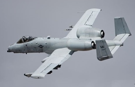
Produced in reply to a specification of 1967, which called for a hard-hitting close-support aircraft, the Fairchild A-10A Thunderbolt II (YA-10A) first flew on 10 May 1972 and was selected by the USAF in preference to the Northrop A-9 on 18 January 1973 after a competitive flyoff, and received a contract for six A-10A aircraft, the first of which flew 15 February 1975. The Thunderbolt’s appearance derives from the care taken to enhance its survival prospects over the battlefield and incorporate maximum fire-power. Absorbing much of the centre fuselage is a GAU-8/A Avenger seven-barrel 30-mm cannon, the muzzle protruding slightly beneath the nose, which can be fired at the rates of 2,100 or 4,200 rounds per minute. The engine location is considered optimum for minimizing hits by ground-fire, and has the additional advantage that the wing and tail mask the infra-red emissions of exhaust gases and therefore affords some protection against heat-seeking SAMs. All of the A-10’s glass is bulletproof and the cockpit itself is surrounded by a heavy tub of titanium. Titanium armor protects both the pilot and critical areas of the flight control system. This titanium “bathtub” can survive direct hits from armor-piercing and high explosive projectiles up to 37 mm in size. The front windscreen can withstand up to a 23 mm projectile. Fire retardant foam protects the fuel cells which are also self sealing in the event of puncture. The airframe has numerous constructional features resistant to battle-damage or conducive to swift repair, such as interchangeable (left or right) flaps, fuselage components, rudders, elevators and main landing gear legs. There are two primary hydraulic systems, each with manual back-up, and the landing gear can be extended under gravity if necessary. Well protected electronically by AN/ALQ-119 jamming pods, plus an AN/ALE-40 chaff and flare dispenser, the Thunderbolt carries a Pave Penny laser designation pod on a pylon to the right of the forward fuselage for accurate marking.
The first production A 10A Thunderbolt II flying on 21 October 1975. Entering service in early 1977, these single seat aircraft are powered by two 9,065 lb thrust General Electric TF34 GE 100 turbofan engines.
Armament comprises a seven barrel, 30 mm gun mounted in the nose, plus a maximum external load of 16,000 lb (7,257 kg) of weapons including air to surface missiles. The General Electric Aircraft Armament Subsystem (30 millimeter Gun System) is located in the forward nose section of the fuselage. The gun system consists of the 30 mm Gatling gun mechanism, double-ended link-less ammunition feed, storage assembly and hydraulic drive system. The General Electric GAU-8/A 30 mm seven barrel cannon, specifically designed for the A-10, provides unmatched tank killing capability. The gun fires armor-piercing projectiles capable of penetrating heavy armor. It also fires a high explosive incendiary round, which is extremely effective against soft skinned targets like trucks. The cannon fires at a rate of 4,200 rounds per minute.
Features of the design are very advanced avionics to enhance operational capability and provision of titanium 737 mph armour for the entire cockpit area.
Avionics equipment includes communications, inertial navigation systems, computer-aided fire control and weapons delivery systems, electronic countermeasures, target penetration aids and self-protection systems. The A-10 employs both electronic and infrared countermeasures against enemy weapons systems. The weapons delivery system incorporates a heads-up display that provides the pilot with references for flight control and weapons employment. The weapons delivery systems include head-up displays that indicate airspeed, altitude and dive angle on the windscreen, a low altitude safety and targeting enhancement system (LASTE) which provides constantly computing impact point freefall ordnance delivery; and Pave Penny laser-tracking pods under the fuselage.
Development of a night/adverse weather (N/AW) two seat version has been initiated, the prototype first flying in 1979. This is intended to allow the pilot to concentrate on control of the aircraft under night or adverse weather conditions, the second seat occupied by a weapons system officer to handle the electronics. The private-venture Thunderbolt N/AW (Night/Adverse Weather) was offered without success.
The A-10/OA-10 have excellent maneuverability at low air speeds and altitude, and are highly accurate weapons-delivery platforms. The A-10 has half the turning radius of the US Air Force’s other primary CAS aircraft, the F-16. After initially leaving a target, the A-10 can turn around and hit the same target again, all in around 7 seconds. Due to its large combat radius, the Thunderbolt II can loiter for extended periods of time, allowing for the coordination required to employ within yards of friendly forces. They can operate under 1,000-foot ceilings (300 meters) with 1.5-mile (2.4 kilometers) visibility. Using night vision goggles, A-10/ OA-10 pilots can conduct their missions during darkness.
The A-10 is capable of sustaining operations on unimproved airfields and the A-10’s rapid re-fueling and re-arming capability allows it to operate from forward bases close to the front lines. It is also capable of refueling in the air.
Altogether the USAF has received 713 aircraft, including A-10B dual control-trainers. Modelled on the A-10N/AW evaluator, the A-10B was in production featuring a second cockpit and taller fins.
The USAFs 33rd Tactical Fighter Training Squadron at Davis-Monthan AFB, Arizona, received its first Fairchild A 10A Thunderbolt IIs in February 1976.
The first combat-ready A-10A wing was the 345th Tactical Fighter Wing, based at Myrtle Beach, South Carolina, to which deliveries began on 20 March 1977. The last of 713 A-10s was handed over to the USAF on 20 March 1984. This was the end of aircraft manufacturing in Hagerstown and Washington County. A-10s were fitted with AIM-9L Sidewinder AAM dual rail adaptors, to allow four missiles to be carried in pairs.
The primary mission of the OA-10 is to act as forward air controller to coordinate and direct friendly air forces in support of land forces. Northrop Grumman acquired the A-10 programme from Fairchild in 1987. In 2000 preparations for the Precision Engagement Program (PEP) upgrade program began. PEP gives the A-10 the capability of deploying precision-guided weapons. The upgrade is carried out in two phases, called Spiral One and Spiral Two. The aircraft is designated A-10C. Between July and October 2004 the first A-10C underwent ground and instrumentation tests prior to the first flight in November 2004. In total 13 A-10C aircraft were for flight testing. The entire A-10A fleet is expected to receive the PEP upgrade. The last aircraft due to be modified before the summer of 2009.
Fairchild A-10A Thunderbolt II Engine: 2 x General Electric TF34-GE 100 turbofan, 9065 lb / 4112-kg Wingspan: 57 ft 6 in / 17.53 m Length: 53 ft 4 in / 16.25 m Height: 4.47m / 14 ft 8 in Wing area: 47 sq.m / 506.0 sq ft Empty equipped weight: 11,321 kg / 24,959 lb MTOW: 50,000 lb / 22,680 kg Wing load : 96.97 lb/sq.ft / 473.0 kg/sq.m Max speed: 439 mph / 706 kph Combat limit: 704 km/h (438 mph) at 1525 m (5,000 ft) Service ceiling 13,636m / 45,000 ft Initial ROC: 1830 m / min / 6,000 fpm Ferry range: 2454 sm / 3949 km Combat radius: 930+ km T/O run (to 15m): 780 m Ldg run (from 15m): 715 m Armament: 1 x 30 mm GAU-8/A Avenger seven-barrel cannon (1174 rds) Pylons: 11 up to 7,258 kg / 16,000 lb Fuel internal: 6225 lt. Air refuel: Yes. Seats: 1
The original Fokker F-27 Friendship was built in Holland. Fairchild has built the F-27 under license from Fokker since 1958. The first F-27 models had a maximum gross weight of 40,500 pounds and seated 44 passengers. Power was supplied by twin 1,720 shp Dart turboprops. When Fairchild merged with Hiller Aircraft, the designation of the airplane was changed to FH-227 and the fuselage was stretched by six feet, giving increased cabin space for passengers and freight. The stretched airliner will accommodate up to 52 passengers. In 1960, power was increased to 2,105 shp. The stretched version was fitted with 2,250 shp engines, and ultimately the FH-227 received a redesigned windshield, stronger landing gear, strengthened rear fuselage, heavier wing skin, propellers of increased diameter and a more powerful 2,300 shp Dart turboprop. Fairchild discontinued building the FH-227 under license from Fokker in 1975.
Engines; 2 x Rolls-Royce RDa-7 Dart Mk.532, 1655kW / 2,300 shp Wingspan; 29.0 m / 95 ft 2 in Length; 25.5 m / 83 ft 8 in Height; 8.4 m / 27 ft 7 in Wing area; 70.0 sq.m / 753.47 sq ft Take-off weight; 20640 kg / 45504 lb Empty weight; 12478 kg / 27509 lb Fuel capacity: 1,364 lb Max. Speed; 483 km/h / 300 mph Top cruise: 270 mph Stall speed: 87 mph Initial climb rate: 1,560 fpm Service ceiling: 28,000 ft Takeoff run: 3,950 ft Landing roll: 4,100 ft Range w/max.fuel; 2500 km / 1553 miles Range w/max.payload; 800 km / 497 miles Seats: 44-52 Crew; 2-3
Fairchild Engine Division started studies for a small, inexpensive turbojet in 1946, for a guided missile the company was developing. In June 1947 the US Navy awarded a contract to develop such an engine to power an air-to-undewater torpedo-carrying missile. The engine, designated the J44, was America’s first expendable turbojet and was required to have a life of only 10 hours.
The Compressor was a mixed-flow, axial and centrifugal type with curved inducer vanes, and it was made of one piece of magnesium alloy casting that required no machining of the blades. Similary to the compressor, the diffuser section, with 3 rows of guide vanes, following the compressor was a single casting requiring no machining.
An annular combustion chamber was made from sheet metal and used in commercialy available oil burners. The single stage turbine had its blades welded on to a forged steel disc. A simple, stock stainless steel tube, with a welded flange at each end, formed the rotor connecting the turbine to the compressor.
There was a bearing before the compressor and aft of the turbine, and a fixed-area exhaust nozzle was used.
In August 1948 the XJ44 made its first run. The first flight was made in mid 1950 when it powered Fairchild’s Petrel Missile. As service trial proceeded, so problems with J44 where thrown up, most of them attribuable to over-simplified production. A lot of changes were required, and development of J44 was completed by October 1954 under designation J44-R-3.
The Improved engine was mounted on a Fairchild C-82 cargo aircraft, then later to each wingtips of the Fairchild C-123B cargo aircraft. Another use of the J44 was one the experimental Bell model 65 VTOL Aircraft.
The main usage of the J44 was to power the Firebee drone, although, with a specific fuel consumption of 1,55 it could not compete with Continental’s J-69 (Licence version of Turbomeca’s Marbore) and it was taken out of production by 1959.
Applications: AQM-34B/C Firebee AQM-41 Petrel Bell Model 65 C-123 Provider
Specifications Type: turbojet Diameter: 0,56 m Length: 2,24 m Frontal area: 0,25 m² Dry Weight, without accessories: 127 kg Dry weight: 363 lb. (165 kg.) Compressor: single stage centrifugal flow compressor Combustors: annular combuster Turbine: two-stage turbine Fuel type: JP-4 Static thrust: 454 kg Maximum thrust: 2450 lb. (10.9 kN) Specific fuel consumption: 0.94 SFC Thrust-to-weight ratio: 6.5:1
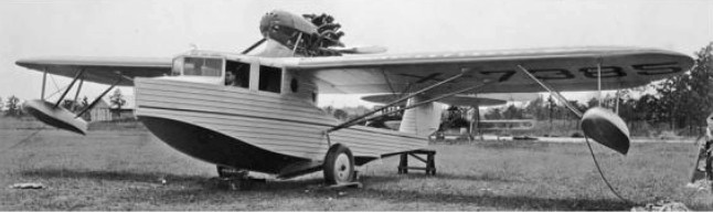
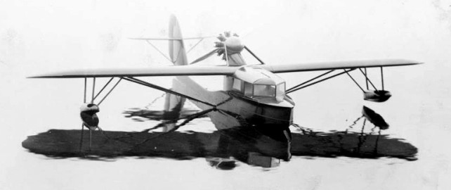
The Fairchild FB-3 (Flying Boat number 3) was an all-metal flying boat designed by Arthur Stelb and developed by the new Fairchild Metal Boat Division of the Fairchild Aircraft Corporation. The prototype was built at Fairchild’s Farmingdale, Long Island facility. The FB-3 was an amphibious high-wing strut-braced monoplane with retractable landing gear, powered by a high pylon mounted pusher configuration radial engine. The two-step hull provided floatation with two outboard floats for stability. The wings used metal spars and ribs with fabric covering. The interior was well finished for its time.
The prototype aircraft (NX7385) was test flown in 1929 but did go into production.
Fairchild FB-3 Engine: 1 × Pratt & Whitney Wasp R-1340, 420 hp (310 kW) Wingspan: 52 ft (16 m) Length: 41 ft (12 m) Maximum speed: 113 kn; 209 km/h (130 mph) Cruise speed: 100 kn; 185 km/h (115 mph) Seats: 4
In 1977, the USAF began to reflect the launch of a program to find a successor to the Cessna T -37B trainer. At the end of 1981, a proposal for participation for a training aircraft of a next generation (NGT / Next Generation Trainer) was sent to Cessna, Fairchild Republic, General Dynamics, Rockwell International and Vought (associated with the German constructor Messerschmitt Bolkow Blohm). The specification was based on twin-turbofan, pressurised cockpit and to have a lower weight at T37. In terms of performance, the Air Force wanted an aircraft capable of a speed of 556 Km / h at 7620 m, and capable of taking off from a runway of 1524 m.
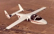
Designed as the Rutan 73, Fairchild Republic Company built a piloted 0.62 scale model of its New Generation Trainer design for the USAF, with the purpose of validating the handling qualities, control surface hinge moments, tail loads and spin characteristics of the full size aircraft.
Powered by a pair of 220 lb st (100 kgp) Microturbo TRS 18 turbojets, the scale aircraft was built by Rutan Aircraft under subcontract from Ames Industrial Corp on behalf of Fairchild and is largely of composite construction.
It was first flown at Mojave, California, on 10 September 1981 with Richard Rutan at the controls, and was expected to make about 35 flights by the end of November before being used for wind tunnel tests.
On July 2, 1982, Fairchild Republic was named the winner of the NGT program, which took the name of Thunder Piglet.
An initial contract was for two T- 46A (FSD) Nos. 84-0492 and 84-0493, 2 airframes for static tests, and an option for 54 of a planned total of 650. Deliveries were scheduled to begin in 1987 with a closure in March 1992.
The flight test program, and the development of pre-types took much longer than expected and led to the cancellation of the program March 13, 1987.
The prototype T-46 first flew in July 1986, but this was largely an academic move as the USAF had terminated the T 46 programme the previous March.
NGT Engines: 2 x Microturbo TRS18 Wingspan: 6.70 m Empty weight: 1,000 lb (454 kg) Gross weight: 1,600 lb (726 kg)
T 46 Engines: 2 x Garrett F109 GA 100 turbo fans, 1,330 lb thrust
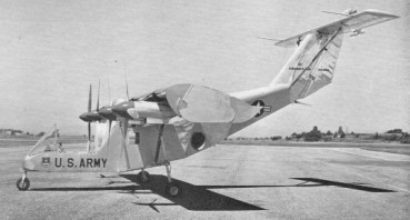
Another deflected slipstream type, similar in principle to the Ryan VZ 3, the Fairchild M 224 achieved less success. It was a two seat high-wing monoplane with a single 1,024 hp General Electric YT58 GE 2 turboshaft engine driving four propellers each of 8 ft 5 in diameter. The wing had 50 per cent chord flaps and endplates. For vertical take off, it was intended to operate at a ground angle of 30 degrees. Control in the hover was by means of small tail fans above the T tailplane for pitch and yaw, and by differential pitch on the outer propellers for roll. Tethered trials with the VZ 5 (56 6940) began on November 18th, 1959, but no free flights were made.
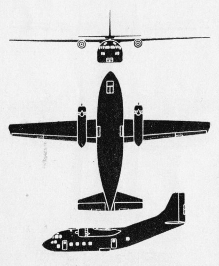
Chase Aircraft developed the larger C-123 Avitruc, first flown 14 October 1949, derived from XG-20 cargo glider. Chase Aircraft constructed the first five examples before Fairchild took over production. Taken over by Fairchild as C-123B and renamed Provider. An XC-123A prototype (four General Electric turbojets) flew on April 21,1951: first flight of a U.S. transport powered by jet engines. Chase became wholly owned subsidiary of Willys Motors Inc. of Toledo, Ohio, in 1953, itself owned by Kaiser- Fraser.
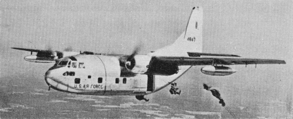
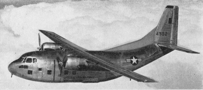
A production order for 300 C-123B, held by the Kaiser-Frazer Corporation (which had acquired a majority interest in the Chase company in 1953), was cancelled in June 1953. New bids were asked for, as a result of which production of the C-123B was assigned to Fairchild. The first Fairchild-built C-123B flew on 1 September 1954 and production aircraft entered service with the USAF’s 309th Troop Carrier Group in July 1955. Orders totalling more than 300 aircraft were completed by mid-1958, six going to Saudi Arabia and 18 to Venezuela.
The M.205 was designated C.123B, H and J.
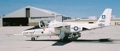
In 1955 the prototype C-123B was fitted experimentally with two Fairchild J44-R-3 1000-lb static thrust turbojet engines mounted at the wingtips to provide auxiliary power for use in an emergency. As a result ten production aircraft were modified into C-123J with P&W 2,500 bhp R-2800-99W radials and turbojet engines fitted. Meanwhile a small number of C-123H had been produced with wide-track landing gears.
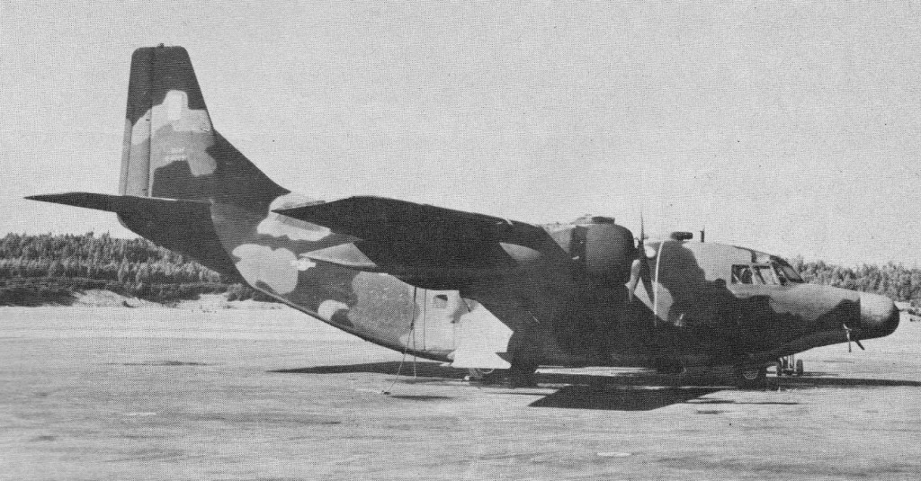
The prototype YC-123H was later experimentally fitted with CJ610 auxiliary turbojet engines and flown on 30 July 1962. After successful tests of a prototype C-123H Provider with jet pods in Viet Nam operations in 1963, the USAF wanted to modify 40 to 50 C-123’s to add a pair of General Electric CJ610 jet engines of 2859 lb thrust to go with the C-123’s standard Pratt & Whitney R-2800’s. Funding may not have been available because of heavy expense of B-52 modification. 183 more C-123B were given 12.68kN General Electric J85-GE-17 auxiliary turbojet engines in underwing pods and designated C-123K (M.473). Some were further converted to AC-123K Spectre gunships for service during the Vietnam conflict.
One of two NC-123X modified into BLU ‘bombers’ for blasting enemy on the trail
The C-123 grossed out at 60,000 lbs and cruised on piston power at 160 knots.
C-123B
When C-123 production ceased on 31 July 1958, Fairchild had built 303, 138 more than the original contract called for.
By 1956, Stroukoff Aircraft Corporation had already gained experience working on the C-123 Provider, having completed two contracts based on that airframe. During November 1954 the Air Force assigned Stroukoff Aviation one of the Providers to be equipped with the system of boundary layer control.
Its YC-123D had introduced a Boundary Layer Control (BLC) system to the C-123B. With the aid of the turbocompressor air was selected from under the inboard flaps between the fuselage and the pods and was blown out through the slots above the ailerons and the outboard flaps. The modernized aircraft XC-123D successfully underwent tests, after showing low stalling speed, small takeoff and path. This greatly improved landing and take-off performance, gross weight capability, and lowered the C-123’s stall speed.
The Air Force hurried to give Stroukoff a contract to build a troop series of six XC-123D. However the head of the firm proposed a more attractive modification, finished in accordance with the advanced concept “Pantobase” (being rested everywhere). The aircraft had a pressurized fuselage, lower part of which were attached the form, which resembles the bottom of boat, usual chassis, two removed water skis even two underwing floats. It could be operated practically from any surface: the earth, water, ice, snow and sand.
The YC-123E had been another experiment in improving the C-123’s ability to operate wherever it might need to, introducing Stroukoff’s own Pantobase system: two high-stress skis fitted to the lower fuselage, wingtip mounted floats, along with sealing the fuselage itself. The first flight took place on 28 July, 1955 and this gave the YC-123E the ability to operate on water, as well as ice and snow, and with the BLC from the previous YC-123D, the new aircraft could effectively be operated from almost any runway surface available, and airstrips of shorter length.
Engines; 2 x P+W R-2800-99W, 1840kW Take-off weight; 27240 kg / 60054 lb Empty weight; 14100 kg / 31085 lb Wingspan; 33.6 m / 110 ft 3 in Length; 23.3 m / 76 ft 5 in Height; 10.4 m / 34 ft 1 in Wing area; 113.6 sq.m / 1222.78 sq ft Max. speed; 392 km/h / 244 mph Ceiling; 7000 m / 22950 ft Range w/max.fuel; 2350 km / 1460 miles Crew; 2
C-123B Assault transport. Engines: 2x Pratt & Whitney R2800-99W, 2500 h.p. Wingspan: 110 ft Length: 75 ft. 9 in Loaded weight: 71,000 lb Max. speed: 245 m.p.h. Ceiling: 29,000 ft. Typical range: 850 miles at 205 mph at 5,000 ft with full load. Crew: 2 Capacity: 61 troops or 16,000 lb cargo.
C-123J Engines: 2 x P&W R-2800-99W radials, 2,500 bhp & 2 x J44-R-3 turbojet, 1000-lb thrust.
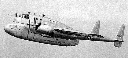
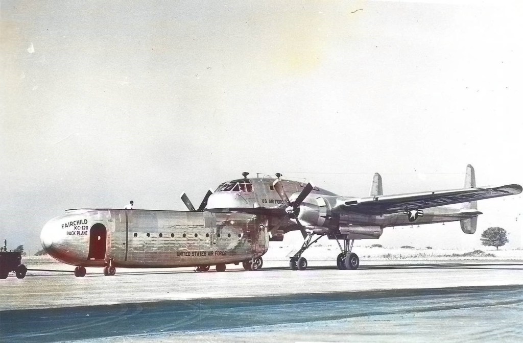
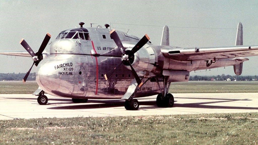
Recognizing that the loading and unloading process could become lengthy and keep aircraft on the ground for inordinately long periods of time, Fairchild engineers devised a modular cargo pod that, in theory, could be quickly and easily attached to and detached from the aircraft. The insect-like aircraft could fly with or without the cargo pod.
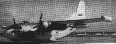
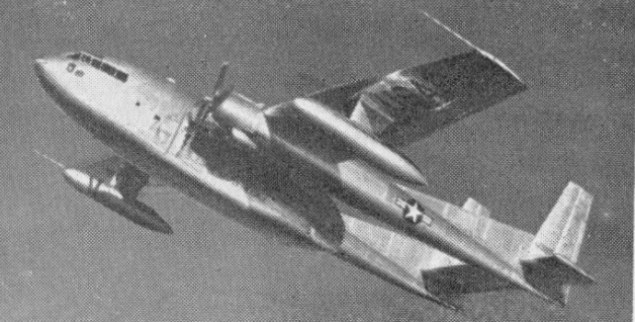
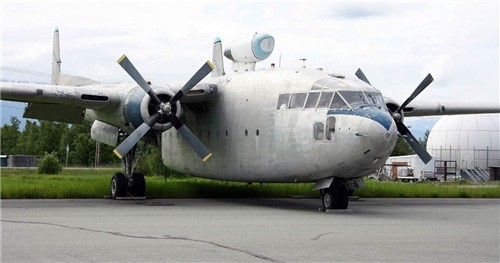
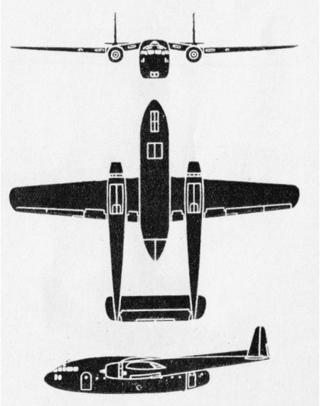
The conversion of one C-119B was to meet a USAF requirement for an experimental detachable-fuselage transport. C-119B wings and tail surfaces were combined with a new upper fuselage with a flat surface. A lower component with a flat upper surface, and incorporating a cargo compartment, could be mated with the Packplane.
The flight deck was in the upper component, and the type could be flown with or without pack and it was intended that various packs for different military operations would be provided.
When an aircraft arrived, crews could quickly disconnect the cargo pod it was carrying and reattach a preloaded pod in its place. This would minimize the amount of time the aircraft spent on the ground, theoretically moving more cargo over the course of a day.
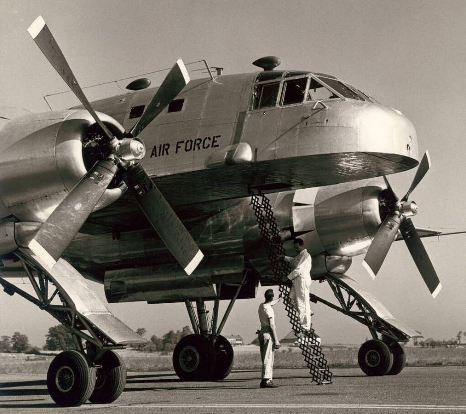
The quadricycle landing gear solved the problem of loading and unloading the cargo pod but presented new problems, particularly with ground towing. Special equipment was required to keep both front wheels tracking parallel to each other when backing up. This equipment could be carried in a pod but had to be left behind when flying without a pod attached. The unique landing gear also precluded “power backs,” or utilizing reverse thrust to back the aircraft up on the ground.
Aerodynamically, it also presented some challenges. Test crews discovered insufficient lateral and directional control at low speeds. Notably, during takeoff, the aircraft’s left-turning tendency could not be overcome by full right rudder. Their solution was to utilize asymmetric power until reaching 35 knots, at which point full power could be applied. The unique landing gear also had to be retracted immediately after liftoff, as it produced large amounts of drag during the retraction sequence.
First flown on 11 August 1950, flight test reports indicate that at a power setting of 2260 BHP, the XC-120 with a pod installed cruised at 218 knots—only 14 knots slower than flight without the pod. The pod weighed approximately 9,000-10,000 pounds. Test pilots also noted that the wheel-well doors were hanging approximately one and a quarter inches open in flight during the entire test program, but this would have been the case with or without a pod attached.
With the pod attached, the absolute ceiling with one engine inoperative at 63,000 pounds (1,000 pounds below maximum takeoff weight) was only 3,300 feet. Under the same conditions, the maximum rate of climb at 2,000 feet was between 10 and 50 feet per minute.
Note the bulges beneath the engines, necessary to contain the retracted forward wheels of the landing gear.
Evaluation crews discovered that attaching or removing the pod required an “unusual” amount of time due to the slow hoist mechanism, and doing so in high or gusty winds proved challenging, requiring even more time.
In 1952, only a couple of years after the XC-120’s first flight, the program was cancelled, and the sole XC-120 was ultimately scrapped.
XC-120 Engine; 2 x Pratt & Whitney R-4360-20, 2435kW Wingspan; 33.3 m / 109 ft 3 in Length; 25.3 m / 83 ft 0 in Height; 7.6 m / 24 ft 11 in Crew; 5 Passengers; 66
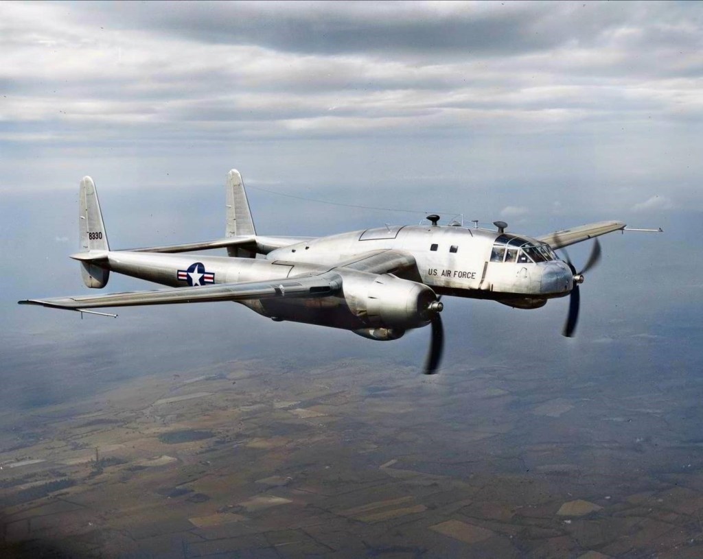
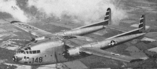
During 1947 Fairchild developed an improved version of the C-82, the XC-82B prototype being a conversion from a production C-82A. It differed primarily by having the flight deck resited into the nose of the aircraft and the installation of 1976kW Pratt & Whitney R-4360-4 Wasp Major 28-cylinder radial engines.
The M.105 was designated XC.119A Following service tests the M.110 was ordered into production as the C-119B Flying Boxcar (55 built), these having the fuselage widened by 0.36m, structural strengthening for operation at higher gross weights, and more powerful R-4360-20 engines, and M.110 / C.119C. Accommodating up to 62 paratroops, and with increased cargo capacity, the C-119s serviced during operations in Korea and Vietnam. C-119s also served with the air forces of Belgium, Brazil, Ethiopia, India, Italy, Nationalist China and South Vietnam, many supplied under the Military Assistance Program.
C-119F
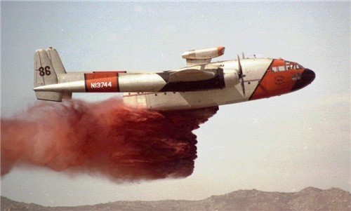
In addition, some surplus military aircraft, both C-82s and C-119s, were acquired by civil operators.
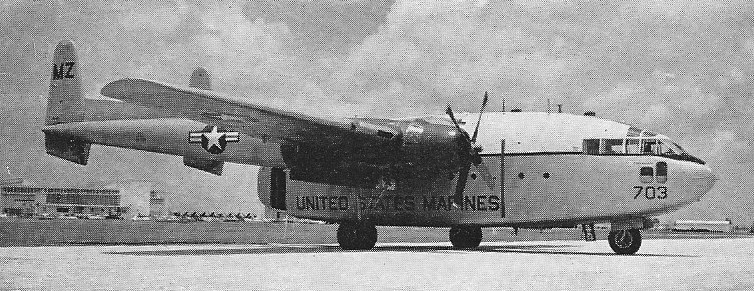
The Fairchild AC-119G ‘Shadow’ and AC119K ‘Stinger’ gunships were a stop-gap replacement for the AC-47 as there were not enough spare C-130s around for conversion at the time, under the AC-130 Gunship 2 programme.
The C-119G is similar to the C-119F but has Aeroproducts airscrews. The C-119B and -G are designated R4Q-1 and -2 by the US Marines.
C-119G
The AC-119G was armed with four 7.62mm minigun pods and used for the support of troops in contact with the enemy and for airbase defence. It was about 25 per cent more effective than the AC-47. The AC119K, with its additional pair of underwing jet pods and improved armament in the shape of two 20mm cannon to supplement the four miniguns, was used exclusively in the truck-hunting role over the Ho Chi Minh Trail. The first AC-119G ‘Shadow’ squadron arrived in Vietnam in November 1968 and the first AC-119K ‘Stinger’ squadron a year later in November 1969.
The M.160 was designated C.119H. The C-119H was an extensively redesigned version of the C-119 Packet with 2 x 3500 h. p. Wright Turbo-Cyclones, increased wing and tailplane span, and all fuel carried in external underwing tanks. Payload increased to 27,200 lb. No production order.
C-119H Skyvan
In the early 1950s, the number of Fairchild employees reached approximately 10,000 who built 1112 C-119s between 1948 and 1952.
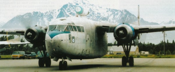
In 1961 Steward-Davis Inc. of Long Beach, California, developed a Jet-Pak conversion for C-119 aircraft. This involved the installation of a 1542kg thrust Westinghouse J34-WE-36 turbojet engine in a specially-developed nacelle mounted on the upper surface of the wing centre-section.
At least 26 Indian Air Force C-119s had a more powerful HAL-built Orpheus jet pod to enable them to operate with greater payloads under ‘hot and high’ conditions.
In 1967 Steward-Davis built the Stolmaster C-119 conversion with quick-attach J34 jet-paks, registered N383S.
C-119F Engines: 2xWright R3350-85WA, 3350 h.p. Wingspan: 109 ft. 3 in. Length: 86 ft. 6 in. Loaded weight: 72,800 lb Max. speed: 270 m.p.h. Ceiling: 22,000 ft. Typical range: 2,300 miles at 205 m.p.h. Crew: 4 Passenger capacity: 42-78.
C-119G Engines; 2 x Wright R-3350-85, 2610kW Max take-off weight; 33747 kg / 74400 lb Empty weight; 18136 kg / 39983 lb Wingspan; 33.3 m / 109 ft 3 in Length; 26.37 m / 86 ft 6 in Height; 8.0 m / 26 ft 3 in Wing area; 134.43 sq.m / 1446.99 sq ft Max. speed; 470 km/h / 292 mph Cruise speed; 322 km/h / 200 mph Ceiling; 7300 m / 23950 ft Range w/max.fuel; 3669 km / 2280 miles Crew; 5
C-119G Engines; 2 x Wright R-3350-32W, 3599 hp Empty weight; 38,751 lb Normal loaded weight: 64,000 lb Max take-off weight; 72,800 lb Max. speed; 296 mph at 17,000 ft / 258 mph at SL ROC; 800 fpm Range w/max.fuel; 3480 miles Wingspan; 33.3 m / 109 ft 3 in Length; 26.37 m / 86 ft 6 in Height; 8.0 m / 26 ft 3 in Wing area; 134.43 sq.m / 1446.99 sq ft
C-119H Skyvan Engines: 2 x 3500 h. p. Wright Turbo-Cyclone Span: 148 ft Weight: 85,900 lb Cruising Speed: 190 mph Payload: 27,200 lb