UK
Formed in 1962 to build Piel CP.301 Emeraude, modified to comply with British certification requirements and known originally as the Garland-Bianchi Linnet.
Post WW2
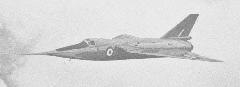
Fairey FD.2 Delta
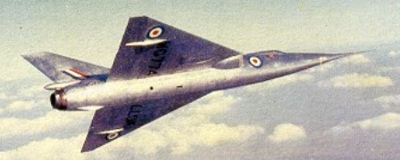
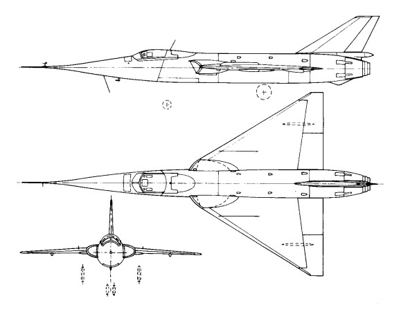
The Delta 2 was built to investigate the characteristics of flight and control at transonic and supersonic speeds. A 60 degree delta, one feature was a nose that drooped 10 degrees for landing for visibility.
The first made its maiden flight on 6 October 1954. Powered by a 12,000-lb (5443-kg) afterburning thrust Rolls-Royce Avon RA.5, the initial F.D.2 secured the first world air speed record at more than 1000 mph (1609 km/h) in March 1956, when an average of 1132 mph (1821 km/h) was recorded in two flights, piloted by Peter Twiss.The second aircraft had the 13,000-1b (5896-kg) afterburing thrust Avon RA.28 and helped to expand the F.D.2’s flight envelope in an important research programme.
On 10 March 1956 the RA.5-powered aircraft (flown by Peter Twiss) became the first aircraft to set an over-1,000mph world speed record, with an average of two flights of 1,821km/h.
The first machine was later revised as the British Aircraft Corporation 221 to evaluate the ogival wing proposed for the Anglo-French supersonic airliner that finally appeared as the BAC/Aerospatiale Concorde. The Concorde also adopted another F.D.2 feature, the drooping nose that gave the pilot an adequate field of vision for takeoff and landing.
Fairey F.D.2
Engine: 1 x Rolls-Royce “Avon” 200 turbo-jet, 44.5kN
Max take-off weight: 6298 kg / 13885 lb
Empty weight: 4990 kg / 11001 lb
Wingspan: 8.18 m / 26 ft 10 in
Length: 15.74 m / 51 ft 8 in
Height: 3.35 m / 10 ft 12 in
Wing area: 33.44 sq.m / 359.94 sq ft
Max. speed: 2092 km/h / 1300 mph
Range: 1336 km / 830 miles
Crew: 1
Fairey FD.1
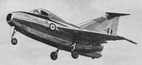
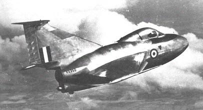
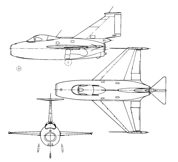
The Fairey FD.1 was produced as a prototype for the investigation of the handling characteristics of a planned vertical take-off fighter (using an inclined ramp). For that reason had provision for four small rocket engines mounted round the efflux of the Derwent engine. These rocket engines were never fitted, and with its very small wing and high wing loading, the F.D.1 required a very long run to take off.and first flew on 12 March 1951, but then adapted for research into the flying qualities of delta-winged aircraft. Powered with a 3600lb (1633-kg) thrust Derwent 8 turbojet. The type had poor handling qualities and was soon abandoned.
Engine: 3600lb (1633-kg) thrust Derwent 8 turbojet
Empty weight: 3084 kg / 6799 lb
Wingspan: 5.95 m / 19 ft 6 in
Length: 7.99 m / 26 ft 3 in
Max. speed: 1011 km/h / 628 mph
Fairey 17 Gannet / GR.17/45
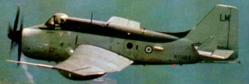
Built as a carrier-based anti-submarine warfare (ASW) aircraft, Fairey’s prototype was known initially as the Type Q. First flown on 19 September 1949, the first and second prototype were of two-seat configuration. The third prototype (which first flew on 10 May 1951) was more representative of production aircraft with three cockpits to accommodate the pilot (forward), observer/navigator (centre), and radio-radar operator (aft).
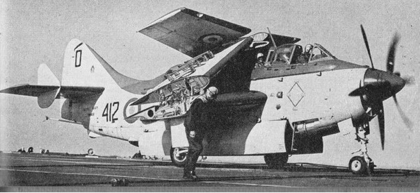
Of all-metal stressed-skin construction, this large mid-wing monoplane had mechanically folding wings to facilitate carrier stowage, and its deep fuselage was able to carry all its major strike weapons internally. Up to 16 air-to-surface rockets could be carried beneath the wings. The Armstrong Siddeley Double Mamba turboprop engine, comprised two turbine engines with individual co-axial contra-rotating propellers. Either engine could be shut down independently and its propeller feathered so that the aircraft could cruise economically. It was the first aircraft in FAA service to combine the ‘hunter/killer’ role for ASW.
The first operational squadron was formed on 17 January 1955. AS.1 and AS.4 aircraft, as well as T.2 and T.5 trainers, served with the FAA until gradually superseded by Whirlwind helicopters from 1958.
The Gannet AEW.3 was first flown from Northolt on 20 August 1958, designed for airborne early-warning duties with the Royal Navy. One of the newcomers at the 1958 Farnborough display was the prototype Gannet AEW.3.
On 1 February 1960 the Gannet AEW.3 early-warning variant began to enter service, having a more powerful Double Mamba engine and a large radome mounted beneath the fuselage. Its pilot was accommodated in a forward cockpit and the two radar operators were seated within the fuselage. A total of 44 of these were built, the later examples by Westland Aircraft which took over the Fairey factories in 1960. The AEW.3 which went to sea aboard HMS Ark Royal in the summer of 1970 were the last Fairey-designed first-line aircraft to serve with the FAA.
The RAAF operated 36 Gannet, ordered in 1953. Four Gannet T.2/T.5 were also ordered in 1953. The first delivered to the RAAF during October 1955 and the last in September 1958.
The AS.4 was also used by the German Navy (15) and Indonesian Navy (16).
Fairey Gannet AS1/4
Engines: One 1,950 eshp Armstrong Siddeley Double Mamba 100 turboprop / One 3,035 eshp Armstrong Siddeley Double Mamba 101 turboprop
Wing Span: 54 ft 4 in
Length: 43 ft
Height: 13 ft 8.5 in
Empty weight: 15,069 lb
Loaded weight: 19,600 lb
Initial Rate of Climb: 2000 ft/min
Ceiling: 25,000 ft
Speed: 299 mph
Range: 662 miles
Crew Three
Armament: 2 x torpedoes in bomb bay / 16 x 60 lb rocket projectiles under wings
AS.4
Engine: One 3,035 eshp Armstrong Siddeley Double Mamba 101 turboprop
Wingspan: 54 ft 4 in
Length: 44 ft 6 in
Wingarea: 482.8 sq.ft
Empty weight 15,069 lb
MTOW: 21,600 lb
Max speed: 310 mph
Service ciling: 25,000 ft
Max range: 943 mi at 196 mph
Fairey Gannet T.2
Engines: 1,950 eshp Armstrong Siddeley Double Mamba 100 turboprop – T2
Empty weight: 15,069 lb
Loaded weight: 19,600 lb
Wing Span: 54 ft 4 in
Length: 43 ft
Height: 13 ft 8.5 in
Crew: 4
Initial Rate of Climb: 2000 ft/min
Ceiling: 25,000 ft
Speed: 299 mph
Range: 662 miles
Armament: Guns: None / Bombs: 2 x torpedoes in bomb bay / 16 x 60 lb rocket projectiles under wings
Fairey Gannet T.5
Engines: 3,035 eshp Armstrong Siddeley Double Mamba 101 turboprop – T5
Empty weight: 15,069 lb
Loaded weight: 19,600 lb
Wing Span: 54 ft 4 in
Length: 43 ft
Height: 13 ft 8.5 in
Crew: 4
Initial Rate of Climb: 2000 ft/min
Ceiling: 25,000 ft
Speed: 299 mph
Range: 662 miles
Armament: Guns: None / Bombs: 2 x torpedoes in bomb bay / 16 x 60 lb rocket projectiles under wings
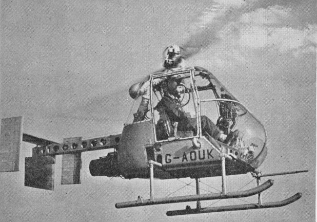
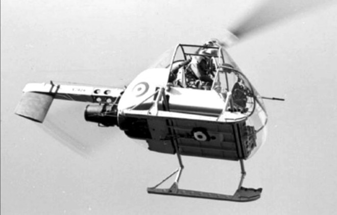
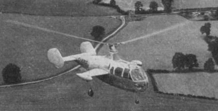
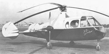
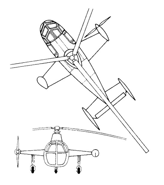
Fairey Ultra-Light Helicopter
During 1953 the War Office collaborated with the Air Ministry and the Ministry of Supply in the formulation of a specification for a simple and relatively inexpensive small helicopter for use by the Army for reconnaissance and other secondary duties such as casualty evacuation and training. The requirements were severe in terms of vertical climb performance, in tropical as well as temperate conditions, though endurance and speed were less stressed. The helicopter had also to be capable of being dismantled and assembled easily and quickly and of being transported on a standard Army three-ton truck.
The specification was sent to helicopter manufacturers in the British aircraft industry, with requests for tenders, and some half-dozen designs were submitted. Fairey eventually won the contract in July 1954 and a preliminary order for four prototypes, to specification H.144T, was placed. Two more were planned as a private-venture investment.
Fairey believed that a rotor-tip drive would be ideal for the Ultra-light Helicopter (as it was named), and preliminary studies showed that a tip-jet-driven version could be designed to do better than meet the requirements. A suitable small turbojet power source was already available in Britain — the French Turbomeca Palouste BnPe.2, which had been re-engineered with the turbine in Nimonic 90 alloy and was built under licence by Blackburn and General Aircraft.
To provide tip-jet air pressure in addition to residual thrust an oversize centrifugal compressor was fitted, and the excess delivery was bled off from the casing surrounding the annular combustion chamber. Untainted air was thus obtained at an initial maximum pressure of about 2.8kg/sq.cm. With this available pressure it would have been possible to design the rotor for operation using simple air jets, but, with their background of experience of fuel-burning pressure-jets, these were employed.
The compressed air was delivered, via a lagged duct, to the rotor head and, with metered fuel from the same tank as that supplying the gas turbine, and carried by centrifugal force to the tip-jets. There was a manually-operated blow-off valve for use when the engine was being ground-run, and, later in the test development, when rotor-power needed to be cut so that rapid autorotative descents could be made.
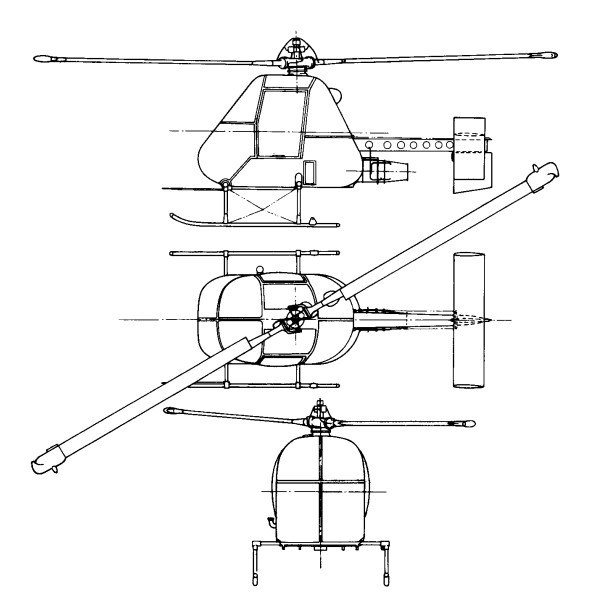
With the ample power available the rotor was designed to operate at high revolutions and to have a small diameter (8.53m), thus meeting the need for compactness. Two of the later variants were fitted with a slightly bigger diameter rotor (9.75m) so as to improve the performance. The small diameter of the rotor permitted the mechanical design and control system to be simplified. No drag hinges were employed and the two blades formed a see-saw combination without individual flapping hinges.
A direct tilting-head type of control was employed in the first prototype, but an irreversible hydraulically-powered system for the cyclic-pitch control was designed (together with a flexible pylon) and fitted to this and to later aircraft. The pilot’s controls were those normal for helicopters — with a collective-pitch lever which carried a twist-grip throttle for increasing engine revolutions and consequent air pressure for the tip-jets, and a stick for control in roll and pitch, but the rudder-pedal directional control was through a steel-skinned rudder on which the jet efflux impinged.
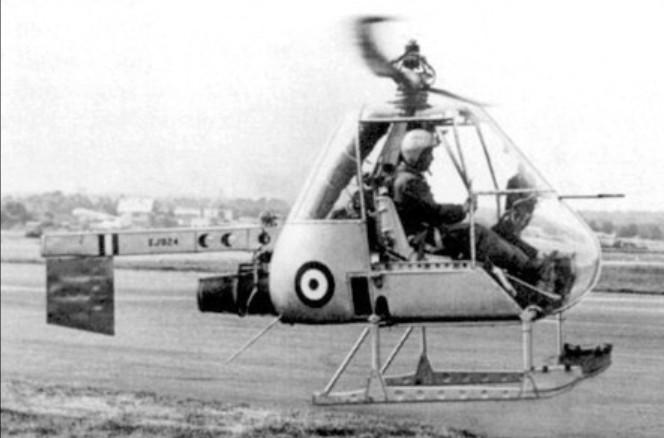
The Ultra-light was very simple in construction, the basis of which was a large light-alloy box containing the bag-type fuel tank. From the centre of this box rose the rotor pylon on which the remainder of the aircraft was, so to speak, hung. To the rear was attached a box-girder boom, under which the engine was slung, carrying the rudder — or rudders and an adjustable tailplane in later versions. This boom had a transport joint aft of the engine mounting. The crew’s seats (the observer facing aft in the proposed Army version) were on the basic box structure. The undercarriage consisted of a pair of skids attached to tubes running across the underside of the box.
The initial flight of the first prototype, XJ924 (F.9423), was made at White Waltham by W. R. Gellatly, on 14 August, 1955 – only about 13 months from the start of design work — and it was shown and flown at the SBAC exhibition and display at Farnborough early in the following month.
Progress on the original basis was, however, to be overtaken by events. Before mid-1956 the Ministry of Supply had, for reasons of economy, ceased to support the Army project, and development of the Ultra-light was continued by Fairey on a private-venture basis, with considerable and expensive efforts to develop the original design and to sell it to prospective Service and civil operators.
There have been some considerable differences, among semi-official and other records, of the actual identities of the various Ultra-lights, of the total number completed and of the sequence in which they were produced. The principal difficulty in straightening the records has been caused by the fact that the original order ‘bookings’ were changed. Four (F.9423—9426) were planned to meet the original Ministry of Supply contract and two more (F.9427—8) were built by Fairey on a private-venture basis. After a certain amount of work had been done there were interchanges of components and then, following the Ministry cancellation, Fairey increased their private-venture programme.
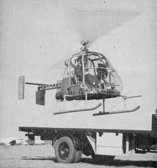
Some uncertain confirmation of the sequence of the completion of the Ultra-lights can be found in the press reports of the SBAC displays of the period. One such report for 1956 said that four had by then been built, the fourth being G-AOUK; another, after the 1957 display, said that five had been built, including G-AOUJ, which was at the show with G-AOUK, and that a sixth, G-APJJ, was under construction.
The serials XJ924, 928, 930 and 936 were allotted to the first four and three of the six were civil-registered following the withdrawal of official support. In order of c/ns, but not necessarily of completion or of initial flights, the six appear to have consisted of the following individual aircraft. The first prototype, XJ924 (F.9423), was the first to fly and was later modified with the hydraulic cyclic-pitch control and flexible pylon already mentioned. The second prototype, XJ928 (F.9424), became a Fairey de velopment aircraft for which a modified cabin was designed so that different loads, such as a stretcher case, could be accommodated; this was registered G-AOUJ and fitted with the hydraulic controls, flying for the first time in the revised form on 1 September, 1957. The third prototype, XJ930 (F.9425), was delivered to the Ministry of Supply. The fourth, XJ936 (F.9426), flown on 24 August, 1956, was the first to be fitted with the hydraulic controls and the flexible pylon; it appeared at die SBAC Display in September 1956 registered G-AOUK, and was the company’s principal demonstration and trials aircraft. Operating from the back of a standard truck, it demonstrated a rate of climb of 6.75m/s and a rate of descent in autorotation of 20m/s. The first of the two original private-venture aircraft, F.9427, was apparently used only for resonance tests and for ground-transport trials.
In the autumn of 1957 G-AOUJ underwent trials aboard the frigate HMS Grenville to determine the practicability or otherwise of operating small reconnaissance helicopters from platforms at sea. More than 70 landings and take-offs were made in winds of up to 62 knots, with the deck sometimes pitching through 3.05-3.66m and rolling up to 14 degrees each way. During 1958 both G-AOUJ and G-APJJ were being evaluated by the Royal Navy. The second, F.9428, was registered G-APJJ and flown initially in 1958; this had a cabin similar to that of G-AOUJ and was used for trials by the Royal Navy, operating from the deck of a destroyer, HMS Undaunted, before going to the Royal Aircraft Establishment, Bedford, and later to the College of Aeronautics at Cranfield.
In 1957 the Piasecki Aircraft Corporation of Philadelphia, USA, had obtained an option to build and the US Army was evaluating it for uses similar to those originally envisaged by the British authorities. Nothing, however, was to follow from these developments.
Typical of the continuous effort being put into Ultra-light demonstrations was the use, early in October 1958, of the stretcher-carrying G-AOUJ, flown by Peter Twiss, in a nuclear-war casualty exercise by the RAMC near Aldershot; the Rotodyne also took part in this exercise. Interest in the Ultra-light had been shown in Canada, and G-AOUJ, with its bulged nose to take a stretcher, and with special navigation and heating/ventilating equipment, was shipped out there later in 1958 for cold-weather trials and demonstrations by Lt-Cdr J. G. P. Morton. In the spring of that year a new draft specification was being drawn up for a version suitable for operation from small ships on anti-submarine duties both in attack (with a homing weapon) and communication roles. This proposal was based on a draft naval staff requirement and was a variation of the aircraft described in a brochure of April 1957 in which a naval strike version had been offered. The three civil-registered Ultra-lights were necessarily designed to meet airworthiness requirements and G-AOUJ and G-APJJ were duly certificated in the autumn of 1958. Work on the project was finally abandoned in 1959.
G-AOUJ has returned to the Helicopter Museum and restoration continued at Weston super Mare, but various parts, and drawings, are missing. A particular problem now is the swash-plate mechanism, of which there are no details.
Engine: 1 x Turbomeca Palouste turboshaft, 185kW
Main rotor diameter: 8.61m
Fuselage length: 4.57m
Max take-off weight: 817kg
Empty weight: 290kg
Max speed: 153km/h
Hovering ceiling, IGE: 3109m
Range: 300km
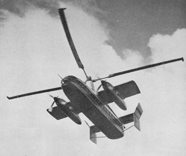
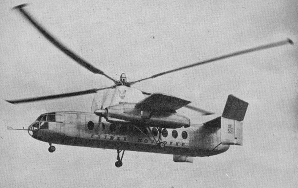
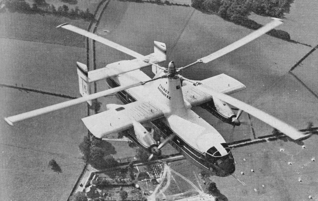
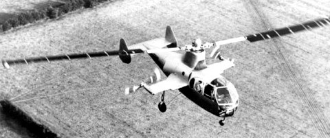
Fairey Rotodyne
With the concept of the convertible helicopter proved on a small scale with the Jet Gyrodyne, the proposal put forward by Dr. J.A.J. Bennett and Captain A.G. Forsyth in 1947 for a large compound helicopter looked viable, and various designs were considered.
The first mention of the project and of the name Rotodyne was made in March 1951 by the Ministry of Civil Aviation’s Interdepartmental Helicopter Committee in its initial report. No details were given, but it was reported to have two propeller-turbines and tip-jets, to have a cruising speed of 217km/h and capacity for 23 passengers. This was probably the Mamba-engined project.
Confirmation of the need for such an aircraft was provided by the British European Airways specification of December 1951 for a short/medium-haul ‘BEAline Bus’. Five manufacturers submitted projects to meet this earlier specification for a 30/40-passenger aircraft. Fairey’s original proposal again incorporated the projected D.H. powerplants. These were in two underwing nacelles, in each of which was located a main gas-turbine driving an auxiliary compressor and, mounted in tandem, a second turbine driving a constant-speed propeller through a reduction gear. Air for this turbine was tapped from the auxiliary compressor of the main engine. The rotor was four-bladed, with pressure-jet units at the tips.
The Gyrodyne had rear clam-shell doors allowing the loading of large motor vehicles. A forward-located door permitted simultaneous entry and exit of passengers. The passenger compartment was 14m long, 2.4m wide, and 1.8m in height. The tail lower tail surfaces were oriented straight down, while the upper surfaces were canted at about a 45 degree angle.
The final version, with two Elands driving propellers and/or auxiliary compressors, was outlined in 1953 and formed the subject of a Ministry of Supply research contract. This became the definitive prototype, leading later, without very fundamental changes, to the proposed production Rotodyne FA-1, or Type Z, of 1959-60, with planned seating for up to 70 passengers. For this, XH249 (F.9430), the Elands could not provide the power required, so two 5,250shp Rolls-Royce Tyne propeller-turbines were envisaged. But in hot/high conditions, even this power would have been only just adequate in the engine-failure on take-off case, and Rolls-Royce suggested separate air-producing engines to supply the tip-jets.
The proposed solution was to install, at the rear of each nacelle, an RB.176 in which a lightweight gas-turbine drove an auxiliary compressor. By this use of separate propulsion and lift power there would be a considerable increase in weight, but the arrangement gave worthwhile gains in off-design conditions. The Fairey pressure-jet unit for the prototype consisted of a circular-section flame-tube fed by three air pipes and one fuel pipe. This was faired within a streamlined nacelle and terminated in a simple propulsive nozzle.
The BEA type specification for the production Rotodyne stipulated an initial climb, at zero forward speed and maximum weight, of not less than 1823m/min, and a noise level, at a distance of 183m, of not more than 96 decibels. With the power planned for the production Rotodyne the noise level for the existing tip-jets would have been about 113 db. To achieve the necessary 17-db reduction in noise level a complete redesign of the pressure-jet was planned. This would have been in two-dimensional form, occupying the last 1.2 metres of each blade, with nine circular flame-tubes in a combustion chamber submerged within the blade profile. Much work was done on silencers, but it was never reduced to the 96 decibels that the authorities demanded.
New test facilities were set up at White Waltham in 1951 for the development of the tip-jets. These consisted initially of a test stand and a rotating rig for chamber-spinning tests. A Rolls-Royce Dart engine, with air tapped from the combustion chambers, was used as a compressor plant for the rig; two other Dart compressor plants were used for the air supply to the rotating stand. On this, a balanced single-bladed rotor, with hingeless hub, was used to investigate tip-jet light-up, regulation, performance, cooling and loads during rotation. Prior to installation on the Jet Gyrodyne, a complete rotor, including hub, blades, jet units and controls, was installed. By the end of 1953 the chamber and rotor had been developed, and the Jet Gyrodyne flew untethered for the first time in January 1954.
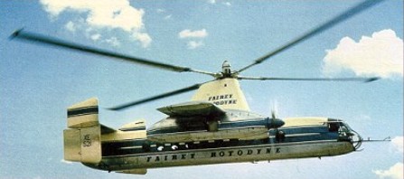
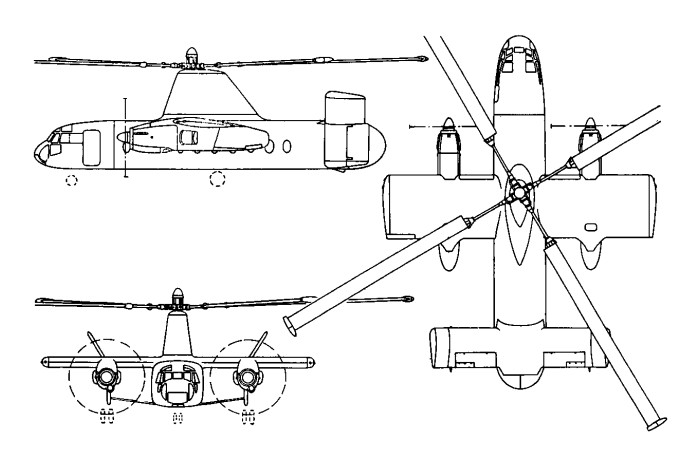
The Rotodyne was a square-section fuselage with untapered 14.17m stub wings on which were mounted two 3000shp Napier Eland turboprops for forward propulsion. The main wheels of the tricycle landing gear retracted forwards into the nacelles, and the nosewheel forwards below the cockpit. Twin fins and rudders, later joined by a central fin, were mounted on an untapered tailplane set on top of the rear fuselage. A large four-bladed rotor for vertical take-off and landing was driven by tip jets which received compressed air from the Eland engines via a compressor. To provide compressed air for the jets the two 2,800shp Napier Eland N.E1.7s operated as dual-purpose powerplants – acting either as normal propeller-turbines or as pressure-generators according to requirements. They were virtually normal Elands up to the rear of the turbine casing, where there was a nine-stage axial compressor driven by the power turbine through an hydraulic clutch. For take-off and landing most of the engine power was absorbed by the compressor, which delivered air to the internal duct system of the rotor. The small amount of remaining power of the engines went to the propellers for yaw control. In cruising flight all the power went to the propellers, with the rotor autorotating. Each engine fed air to two opposing blades so that, in the case of failure of one engine, there would be adequate pressure to keep two jets burning efficiently and giving maximum thrust.
All the earlier flying was completed with the fixed undercarriage while a revised form of retractable undercarriage, with special dampers, was designed and manufactured. This was fitted to the prototype soon after mid-year 1958 when the initial transition trials had been completed and the Rotodyne was being flown faster and for longer periods in the ‘winged autogyro’ mode.
Following the resonance and running tests, the first untethered flight of the Rotodyne, XE521 (F.9429), was made by W. R. Gellatly and J. G. P. Morton at White Waltham on 6 November, 1957, and two further flights, carrying a flight observer, were made on the first day. Originally it had been intended to keep within the ground cushion during the early flights, but the prototype was taken on a circuit of the aerodrome, well above cushion height, on one of the first three flights which were made at a weight close to the 15,000kg maximum.
Until 10 April, 1958, all flights were made in the helicopter mode. On that day, at 1220m, the first transitions were made to and from the autogyro mode and thereafter a stage-by-stage transition technique was further evolved to ensure complete safety at all moments during the manoeuvres. During the 70 earlier helicopter flights, speed had been built up to 250km/h and altitude to 2072m before transition tests were started.

In its original form the control system followed that of the Jet Gyrodyne, with direct roll and fore-and-aft control through the cyclic pitch-change of the rotor-blades; with a trimming ‘elevator’ used to select fuselage attitude (and consequently wing lift) in cruising flight; and with yaw control by differential propeller-pitch at low speeds or when hovering, and by rudders at higher cruise speeds. Early in the test programme it was found that the fore-and-aft attitude control, using the separate functions of cyclic rotor-control and elevator trim, produced some difficulties. The solution was to link the elevator to the longitudinal cyclic control for both slow and high-speed flight and to disconnect the cyclic control when cruising.
Later, when it was found that the economical cruising speed was more like 273km/h than the originally planned 209km/h, it was found that, at higher speeds, the wing was doing too much work and the rotor too little, so that the blades were flapping and the control margins were inadequate. The wing, originally set at an incidence of 4°, was re-set at 0° and fitted with ailerons, the operation of which was linked directly to the cyclic lateral control of the rotor. The outward-sloping upper fins were also moved to the vertical so as to reduce the rolling tendency with yaw. These changes produced a normal ‘aeroplane-type’ rolling control for the pilot, and the situation was further improved later by the fitting of a third upper fin.
Towards the end of 1958 a decision was made to establish a speed record with the Rotodyne. The 100km closed-circuit category was considered to be the most usefully representative of the kind of operation for which the Rotodyne was designed and that in the new convertiplane class (E.2) was chosen. On 5 January, 1959, the Rotodyne was flown by Gellatly and Morton, with Dr D. B. Leason, Fairey powerplant flight observer, and E. J. Blackburn, strain-gauge operator, as ‘passengers’, over a measured circuit between White Waltham and Hungerford, Berkshire. The flight was completed at an average speed of 307km/h – which was 79km/h higher than the equivalent record for a helicopter and nearly 48km/h higher than that for absolute speed in a straight line. At that time the Rotodyne had not yet been modified with the reduced wing-incidence and the fitting of ailerons to improve control at higher speeds. The record, which was confirmed in March, stood until October 1961, when it was beaten by the Russian twin-rotor Kamov Ka-22 Vintokryl convertiplane.
On 16 June, 1959, the Rotodyne was taken outside the United Kingdom for the first time when it was flown to Paris for the 23rd Aeronautical Salon from London’s Heathrow Airport, via the Allee Verte heliport at Brussels and the Issy heliport in Paris before landing at Le Bourget. After demonstrations there, and at Versailles for officers of the North Atlantic Treaty Organization, the Rotodyne was flown back to Heathrow.
During 1959 the wings were given ailerons and increased incidence, and the vertical tail surfaces were also revised. On 7 February 1960, XE521 resumed trials with an added central fin, shortened exhausts and a fully-faired rotor pylon.
Budgetary problems of the time saw the RAF and British Army withdraw their interest and the Rotodyne became a wholly civil project.
During 1958 the Kaman Aircraft Corporation secured a licensing agreement for sales and service in the USA with a possibility of manufacture there. Okanagan Helicopters of Vancouver was interested in three and Japan Air Lines was considering the type for domestic routes. However, the biggest potential customer was New York Airways, which joined with Kaman in a letter of intent for five, plus options on 10, for delivery in 1964.
The provisional order from NYA was for the bigger-capacity, 54/65-seat Rotodyne powered with Rolls-Royce Tyne propeller-turbines and with a gross weight of 22680kg. There had been earlier references to the use of Tynes in the production version, but this order led to the first fuller statements about this version, for the development of which an additional GBP8-10 million was needed. The Government had offered to contribute half this sum, up to a certain fixed maximum, with repayment through a sales levy, but this was conditional on a firm order from BEA. Confirmation of the NYA order depended on several factors — including one that the first ‘Mk.2’ Rotodyne should be flying on test by the autumn of 1961 and another that the noise-level should be acceptable to the airline and airport authorities.
At the Paris Salon in June 1959 a model of the production version had been exhibited in the markings of New York Airways.
Fairey needed up to GBP 10 million to develop this version and was offered 50% of this by the government if BEA would place a firm order. The government contribution was to be a loan, repayable by a sales levy. In 1960 Fairey merged with Westland and although initially the Rotodyne project looked secure, it was not. In April 1960 Okanagan cancelled its order because of the long delivery dates, and five months later New York Airways expressed concern over the delay in production plans. Westland was then involved in taking over Bristol’s helicopter programme as well as with other work in hand. This, together with the ever-increasing weight of the Rotodyne, which reached a stage where the Eland could no longer be developed and the Tyne could not be afforded, led to withdrawal of government support, and the project was cancelled on 26 February 1962. On that date the British Minister of Aviation, Mr Peter Thorneycroft, said that, because of the costs involved, it was necessary to ‘forego the operational advantages’ offered by the military version, and that British European Airways, then its only potential British civil operator, had regretfully concluded that ‘the commercial prospects on their routes were not sufficiently assured to justify the heavy liabilities involved’ in placing a production order. In the absence of any firm order, Westland Aircraft did not feel justified in proceeding with the project.
GBP11 million was spent during the nine years or so following the placing of the original research contract in July 1953. During the final three years of the period, however, financial support had been uncertain and the project suffered from continuing political and other indecisions which made costly forward planning impossible.
The Rotodyne was subjected to a vigorous flight test program of over 350 flights, more than half of them demonstrating 200 hover-to-vertical flight transitions.
Engines: 2 x Napier Eland NE1.7 turboshaft, 2088kW
Main rotor diameter: 27.4m
Wingspan: 14.17m
Fuselage length: 17.88m
Height: 6.76m
Internal cabin length: 14.02m
Loaded weight: 14969kg
Cruising speed: 298km/h
Max range: 724km
Cabin volume: 93cu.m
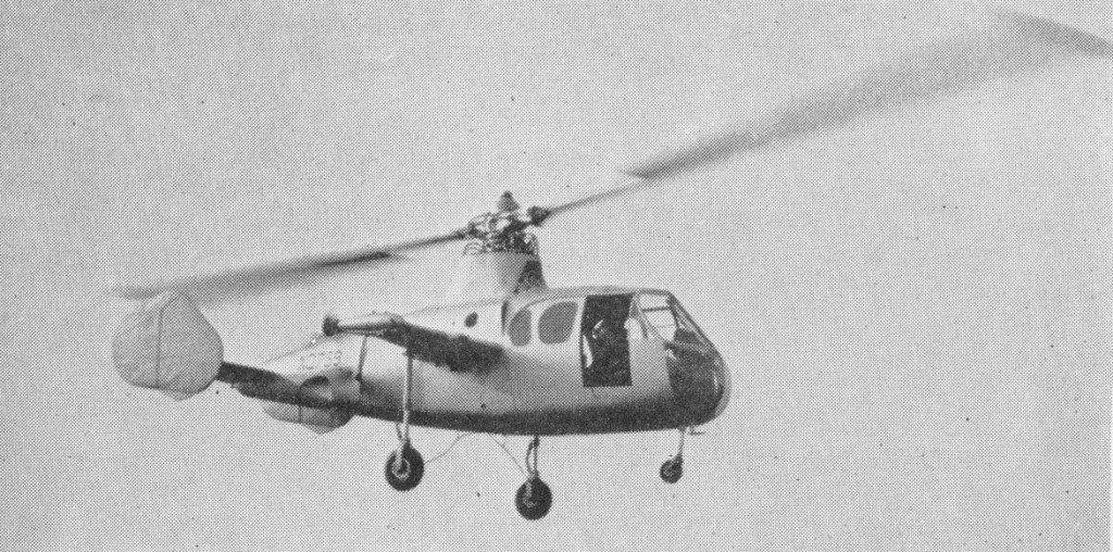
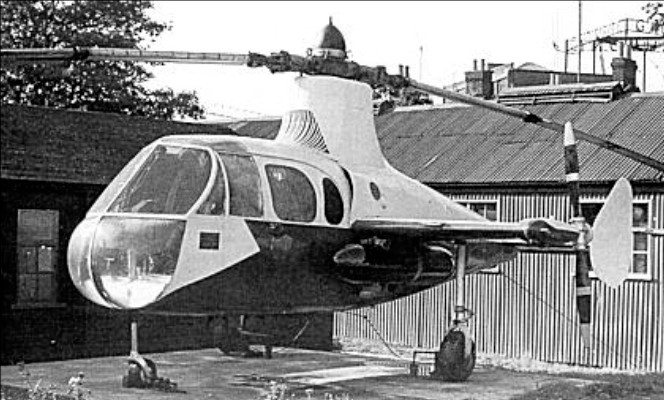
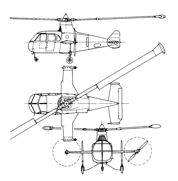
Fairey Jet Gyrodyne
Towards the end of 1953 the surviving second prototype Gyrodyne reappeared in a very different form. A research contract had been received from the Ministry of Supply to try the principles of the tip-jet rotor-driving system.
This was necessary to test the tip-jet, and to develop handling and other procedures for the compound, or convertible, helicopter. By early January 1954 this aircraft, named the Jet Gyrodyne, and carrying the duplicated Ministry serial XD759, which was later to be changed to XJ389, was making tethered flights at White Waltham in the hands of John N. Dennis, who had joined Fairey as helicopter test pilot in June 1949. The first free flight was made in January 1950.
The Jet Gyrodyne retained the fuselage, tail unit, stub wings and tricycle undercarriage of the Gyrodyne, and was also powered by a specially modified Alvis Leonides nine-cylinder radial. The engine was used to drive, through a gearbox and shafts in the stub-wings, two variable-pitch pusher propellers of Fairey design. These propellers provided propulsion in cruising flight and slow-speed directional control through rudder pedals by means of a differential pitch-change which was superimposed on the collective-pitch action. A third drive from the Leonides was taken from the main gearbox, via a friction clutch, to two Rolls-Royce Merlin centrifugal compressors mounted face-to-face under the rotor pylon. Air from these compressors was fed to the fuel-burning pressure-jet units at the tips of the 18.29m two-blade rotor. Unlike that of the Gyrodyne, the rotor had a conventional helicopter control system – with collective-pitch change for varying the overall lift, and cyclic alterations of the blade-angle, by means of a conventional column, to provide fore-and-aft and lateral, or rolling, control.
In the Jet Gyrodyne tip burners, compressed-air from the blowers passed through the rotor blades, while centrifugal force fed the metered fuel through the blades to the jets. The compound, or convertible, helicopter principle is lift for take-off, slow flight and landing was provided by the jet-driven rotor. For transition to cruising flight the compressed air to the rotor tips was progressively reduced and available engine power transferred to the propellers, leaving the rotor as an auto-rotating lift unit which was supplemented (in a very minor proportion for the Jet Gyrodyne) by the fixed wing. The procedure was reversed for a return to the helicopter regime.
The problem for the Jet Gyrodyne was accentuated by, at a gross weight of 2720kg, under-powered for the work it had to perform and the Leonides was normally operated at maximum boost. The Jet Gyrodyne could not quite maintain level flight in the cruising, autorotative, mode. It was not until 1 March, 1955, that a transition was completed by John Dennis. Within four months of this first full transition, the techniques had become well established and transition was no longer being accompanied by a considerable loss of height. The cycle was demonstrated during the SBAC Display at Farnborough in September 1955; while practicing for this demonstration, 65 successful in-flight tip-jet re-lights were accomplished during eight days.
Even during the earlier period of testing, the transition from helicopter to autogyro flight was relatively easy. The basis of the operation was the transfer of engine power from the jet-feeding compressors to the propellers. The pitch of the propellers was progressively coarsened, thus absorbing more power and reducing the air delivery to the jets, which eventually flamed out, and the compressors were declutched. It was found that transition could be made at widely varying speeds, but 128km/h was found to be the most convenient, with a rotor speed of about 210 rpm.
The difficult operation was the transition back to helicopter flight. A great deal of flying was required before the best propeller-pitch and tip-jet re-lighting sequence could be established. A major part of the difficulty was that, with the compressors being driven, there was no reserve of engine power for the propellers during the re-lighting sequence, and the aircraft descended rapidly in autorotation until the jets had been re-lit. So long as the re-lighting was being done over or near an aerodrome there was no particular danger in this situation; a controlled landing could be made, and often was made, in autorotation.
As finally established, the drill was to throttle back momentarily, engage the compressor clutch, switch on the tip-jet ignition and fuel supply, and progressively fine-off the propeller pitch. This automatically opened the intake-valves for the compressors. The tip-jets re-lit when a certain head pressure had been reached and collective-pitch was increased to keep the rotor speed down. Propeller pitch was then slowly reduced to zero so that maximum power was available for the blowers to give full tip-jet thrust.
Because of the need to keep the gross weight down with the limited power available, the Jet Gyrodyne normally carried only sufficient fuel for 15 minutes or so of safe tip-jet burning endurance. Extra tanks were occasionally carried under the wings to provide 30 minutes’ endurance, but, as already noted, there was no particular danger in fuel exhaustion for an aircraft which could make powerless autorotative landings from a best indicated gliding speed of only 72km/h. The high inertia of the big rotor allowed for a few moments of hovering before touch-down.
By September 1956 the Jet Gyrodyne had made 190 transitions and 140 autorotative landings. The techniques were by then familiar and reasonably well understood, so that there was already a sound basis for the procedures required for the Rotodyne, which was to make its first flight a year later.
All the early test flying with the Jet Gyrodyne, including transition from helicopter to autogyro flight and vice versa in March 1955, was done by John N. Dennis. Six Ministry of Supply pilots each flew the Jet Gyrodyne successfully after about an hour’s instruction and practice.
At the time when the Jet Gyrodyne was making its earlier test flights the design team was led by Dr G. S. Hislop, chief designer (helicopters), and Capt A. G. Forsyth, chief helicopter engineer, who was responsible, among other features, for the tip-jets, and shared with Dr J. A. J. Bennett (who had by then left the company) the 1949 British Patent on which the Jet Gyrodyne and Rotodyne concepts were based. Later Jet Gyrodyne flight development was carried out by Sqn Ldr W. R. Gellatly and Lt Cdr J. G. P. Morton, who were to take the Rotodyne through its four years of testing.
Although scheduled for scrapping in 1961, the Jet Gyrodyne was rescued and eventually preserved.
Fairey Gyrodyne / E.4/46 / FB-1 / Fairey-Bennett One

In preparation for the move into rotary-wing development, Fairey had built up a strong helicopter team, led by Dr J. A. J. Bennett, who brought the Gyrodyne proposal to the company in August 1945, and with Sqn Ldr Basil H. Arkell, who joined in January 1946, as test pilot. The first official announcement of the project, a private-venture to specification E.4/46, was made on 3 April, 1946, though no information was then given; at that time the Gyrodyne was known as the FB-1 (Fairey-Bennett One).
Although the broad concept was relatively simple, the translation of this concept into working hardware involved a considerable effort in engineering and other ingenuities. An idea of the amount of ‘machinery’ in the prototype can be gathered from the fact that nearly 50 per cent of the empty weight was contributed by the powerplant and transmission systems. In these there were four primary units: a 520hp Alvis Leonides nine-cylinder radial engine, with its mounting and systems; a main gearbox with first-stage reduction for the rotor and propeller drives, a clutch and freewheel; an upper gearbox with double epicyclic reduction gear, plus the rotor brake; and a gearbox in the starboard wingtip with the reduction-gear and pitch-changing mechanism for the propeller.
The engine power could be transmitted in variable ratios to a three-blade rotor just over 15m in diameter and to the anti-torque propeller on the starboard tip of the stub wing, the Gyrodyne behaved like a helicopter, but the same propeller also provided the necessary thrust for fast flight, when the aircraft looked almost like an autogyro.
The rotor articulation was designed so that the collective-pitch changed automatically according to the power being applied. The throttle lever was designed to be similar in length, movement and effect to the collective-pitch control of a conventional helicopter and was pulled up to increase power and lift. Fore-and-aft and lateral control was provided by a form of tilting head; although the rotor-hub axis did not physically tilt, as in the case of most autogyros, a similar effect was produced by tilting the rotor head in relation to the axis. Stick-shake was eliminated, using suitable safeguards, by controlling rotor-tilt through irreversible hydraulic jacks.
The Ministry of Supply asked for an alternative rotor-hub arrangement to be designed with overriding collective-pitch and cyclic-pitch blade-angle control so that this could be compared on test with the existing system. This normal helicopter control system was required mainly for trimming purposes at altitude and to provide more positive control when hovering after an autorotative approach.
Yaw control was maintained, as with other helicopters, by altering the pitch of the propeller through conventional pedals. Rudders were fitted for directional control during autorotative flight after power failure. An ‘elevator’ in the form of a large trim tab, was used to adjust the fuselage attitude when cruising.
A government contract to Specification E.4/46 was awarded for two prototypes, and the first Fairey Gyrodyne, G-AIKF (provisionally serialled VX591), was exhibited almost complete at White Waltham on 7 December 1946.
After 85 engine-running and 56 rotor-testing hours the first untethered flight was made at White Waltham by Basil Arkell on 7 December 1947, weighing just over 2000kg. Testing continued, with longer flights at gradually increasing speeds, until March 1948, when the Gyrodyne was dismantled for examination. By then a second prototype, G-AJJP, had been completed.
The second prototype, basically similar to the first but with more comfortable interior furnishings befitting its role as a passenger demonstrator, was flying by the time of the next SBAC Display, in September 1948, at Farnborough.
Following re-assembly and further tests, G-AIKF was prepared for an attempt on the international helicopter (Class G) speed record in a straight line. This had long been held unofficially by the German Focke Achgelis Fa 61 and more recently a Sikorsky R-5 had also been unofficially timed at 185km/h in the USA. Two eastward and two westward flights over a 3km course at White Waltham were made by Arkell on 28 June, 1948, at an average speed, for the best pair of opposing runs, of 200km/h. In addition to being a world record, this was the first British national record for any helicopter. The course was along the London-Reading railway line on the north side of the aerodrome, and, as it happened, was 45 degrees off a fairly strong wind, so the probability is that a speed of 225km/h might have been achieved in calmer conditions.
Some ten months later an attempt to set up a 100km closed-circuit record ended in tragedy. During trials on 17 April, 1949, two days before the attempt was to be made, the first prototype Gyrodyne suffered a fatigue failure in the rotor head and crashed at Ufton, near Reading, killing F. H. Dixon and his flight observer, Derek Garroway. Dixon, who joined Fairey in 1936 and was chief test pilot from 1942 to 1945, had since been involved in less arduous flying and other duties, but had also shared much of the development and demonstration flying of the Gyrodyne with Basil Arkell.
The investigation following the accident led to a protracted period of investigation and fatigue-testing, and development ceased. The second prototype was grounded and was afterwards very much modified to reappear more than four years later as the Jet Gyrodyne, the test vehicle for the Rotodyne.

Engine: 1 x Alvis Leonides, 388kW
Main rotor diameter: 15.77m
Fuselage length: 7.62m
Height: 3.10m
Take-off weight: 2177kg
Empty weight: 1633kg
Max speed: 124 mph
Seats: 4-5
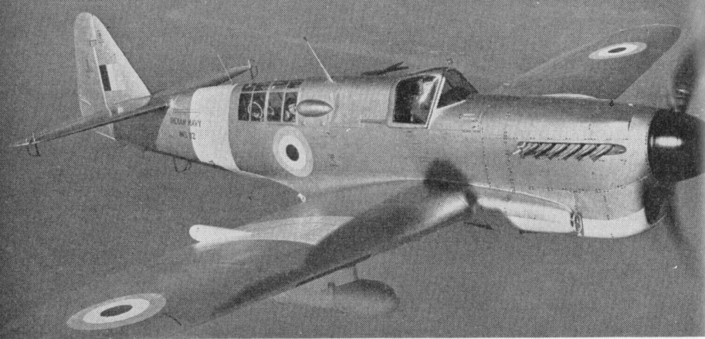
Fairey Firefly

A natural development of the Fulmar two seat fighter, the Firefly was designed by a team led by H E Chaplin to meet specification N.5/40, an amalgamation of the earlier requirements of N.8/39 and N.9/39 which had called for a carrier based fighter with a turret. However, the turret was dropped, and when chief test pilot Chris Staniland flew the first Firefly I on December 22, 1941, it was a clean tandem-seater with manually folding wings containing four 20 mm (0.79 in) cannon and retractable Youngman area increasing flaps. At first there was no requirement for the type to be able to carry bombs or rockets.
It was a stressed skin monoplane with folding elliptical wings housing four cannon and with the trailing edge with Youngman flaps which could be recessed into the wing.
Full production started in August 1942 with the first production F.I flying on 26 August 1942.
Development was satisfactory, and the F.1, with 1730 hp / 1,483kW Rolls Royce Griffon IIB driving a Rotol three-bladed propeller, entered service with 1770 Squadron of the Fleet Air Arm in October 1943 as a two-seat day fighter, subsequently seeing extensive action in all theatres, especially in air to surface attacks against the Japanese. Manoeuvrability and long range made up for poor speed, and the good pilot view and comfortable rear observer cockpit were most welcome. Fairey, at Hayes and Stockport, and General Aircraft built 429 F.Is followed by 376 FR.Is (fighter reconnaissance) with ASH ship and submarine ¬detection radar in a radome under the nose of the fuselage. Each was armed with two 20mm cannon in each wing. Then followed 37 NF.II night fighters, with the large AI.X radar packaged into pods on the leading edge of both wings and with the forward fuselage lengthened to preserve centre of gravity posi¬tion, which was disturbed by the heavy displays in the rear cockpit. Conversions included the NF.I, with American 3 cm AI radar (usually APS 6) in a ventral pod, with other changes including shrouded exhausts, and the FR.IA which was a Mk.I rebuilt almost to FR.1 standard. From the 471st aircraft the engine was the 1990 hp Griffon XII.
The Firefly T.1 was basically an F.1 converted for use as a deck-landing conversion and instrument-flying trainer. The raised rear cockpit was occupied by the instructor. They were usually unarmed, although a few carried two 20mm cannon.

The Firefly T.2 was an armaments trainer, similar to the T.1 with two 20mm cannon and provision for carrying bombs, rockets and long-range drop tanks. The Griffon 12-powered Firefly T.3 was a version of the FR.1 intended specifically to train observers, the rear cockpit being equipped with the fullest possible range of radio and radar equipment.

Not¬able highlights included the attack on the German battleship Tirpitz and a series of strikes on mainland Japan shortly before VJ-Day brought hostilities to a conclusion. In the post-war era, the Firefly demonstrated a considerable degree of versatility, turning its hand to other duties such as target towing and anti-submarine warfare as well as continuing in its primary function of fighter-bomber. By the time production ceased 1,702 had been built, some remaining active with the Fleet Air Arm until as late as 1957 whilst others served with Australia, Canada, Denmark, Ethiopia, India, the Netherlands, Sweden and Thailand.
The Royal Canadian Navy employed 65 Fireflies of the Mk AS5 variety on board its own aircraft carriers between 1946 and 1954. The letters ‘AS’ stand for anti-submarine, which was the intended primary role of the RCN’s Fireflies.
A total of 29 Firefly FR.1s were operated by the RCN after the war.
Availability of the two stage Griffon led to the F.III, reaching 562 km/h (349 mph) with the 2035 hp Griffon 61, but handling was poor.
An extensive redesign resulted in the greatly improved F.IV (postwar FR.4) with 2250 hp Griffon 74 driving a four blade Rotol propeller, which flew for the first time on 25 May 1945. New square tipped wings had reduced span and neat leading edge pods housing fuel (left) and radar (right). Radiators were moved to the inboard leading edge, the area of the tailfin was increased, and the aerodynamics improved. New underwing racks could carry up to 907 kg (2000 lb) of bombs, 16 rockets or drop tanks. Production, all by Fairey, amounted to 160 were completed by early 1948, of which 40 went to the Royal Netherlands Navy. Nearly all those in front line service with Royal Navy carriers saw action in Korea in 1950 53.
Some later being modified to Firefly TT.Mk 4 standard for target-towing duty.
The next basic model to appear was the Mk 5. Similar to the 4, but with the wing folding and locking powered hydraulically, and with additional role equipment. Variants including the Firefly NF.Mk 5 night-fighter, the Firefly FR.5 day reconnaissance fighter and the Firefly AS.Mk 5 antisubmarine patrol aircraft; the last eventually became the most numerous post-war version. All had better communications, navigation and IFF, and the NF and AS having night and search/attack radar. Production totalled 352 between 1947 and 1950, including batches for the Royal Australian and Canadian Navies which served throughout the Korean campaign.
The FR.5 carried the same radar in the starboard wing nacelle as the 4 and was equipped with beam approach, IFF and communications radio. The NF.5 had the same basic radio plus a radio altimeter and other night-flying equipment. The AS.5 was an anti-submarine version and carried special submarine-detection equipment under the wings and fuselage.
In 1951, the Firefly AS.6 entered service as an interim ASW aircraft pending delivery of the Fairey Gannet. It abandoned all fighter pretensions and carried only radar, sonobuoys and antisubmarine weapons. Fairey built 133.
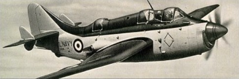
The Firefly 7 of 1953 was produced in two forms, as the AS and T, although it was used mainly as an anti-submarine training aircraft. Powered by a Griffon engine with a ‘chin’ radiator, the three-seat anti-submarine aircraft carried the latest detection devices and sonobuoys for tracking a target at sea. A new blister-enclosed rear cockpit accommodated two radar operators and the aircraft had elliptical long span wings without wing radiators, swept forward wing roots, and a new tail unit.

The remaining 160 Mk 7s were all Firefly T.Mk 7 trainers. Firefly production eventually terminated in March 1956 with the delivery of the last of 24 new-build Firefly U.Mk 8 target drones, but 54 Mk 5s were also converted to this mission, these being known as Firefly U.Mk 9 aircraft. The U.8, U.9 and U.10 were all radio controlled drones or targets. The Fairey Firefly 8 (Rolls Royce Griffon 59) had four cameras in each wing tip fairing to photograph missiles which are directed to its vicinity. For test purposes and other duties it may be flown by a crew of two pilot and observer. Unlike the Firefly 7, from which it was developed, has an arrester hook fitted in the aperture under the fuselage. This is for arrested landings on aerodromes while under radio control. It has an 86 gallon fuel tank between the cockpits. The U.9 was the standard target for development and training with the Seaslug ship to air missile, while the U.10 was a similar rebuild of the AS.7.

All targets had large multi angle high speed camera pods on the wingtips.

In the 1950s more than 450 Fireflys were rebuilt for new roles. The first was the TT.1 target tug, with Mk 2B windmill winch and 2150 m (7053 ft) of cable for a drogue target; some of these had a long career in Sweden. The T.1 operational trainer, 30 of which were supplied to the Royal Navy and a few to other countries, had two separate stepped cockpit canopies, dual control and changed equipment. Most were unarmed, but some had two cannon.
Operationally, British Fireflies of various marks saw considerable post-war action, taking part in the Malayan confrontation between 1949 and 1954 as well as the Korean War, whilst the Dutch Firefly FR.Mk 1 aircraft undertook combat duty against rebel forces in the Dutch East Indies.
In total, 1623 Fireflies left the assembly lines.
Firefly F.I
c/n 1-470
Engine: Rolls-Royce Griffon IIB, 1730 hp
Wingspan: 44 ft 6 in / 13.56 m
Wing area: 327.979 sq.ft / 30.47 sq.m
Length: 37 ft 7 in / 11.4 m
Height: 13 ft 7 in / 4.15 m
Empty weight: 9750 lb / 4422 kg
Loaded weight: 14,020 lb / 6359 kg
Wing loading: 42.85 lb/sq.ft / 209.0 kg/sq.m
Max speed: 316 mph / 509 kph / 275 kts
ROC: 1700 fpm / 518 m/min
Service ceiling: 28,000 ft / 8534 m
Range internal fuel: 580 mi / 933 km
Range w/max.fuel: 1720 km / 1069 miles
Armament: 4 x 20mm Hispano cannon
Bombload: 2000 lb / 906 kg
Crew: 2
Firefly I
c/n 471-
Engine: Rolls-Royce Griffon XII, 1990 hp
Wingspan: 44 ft 6 in / 13.56 m
Length: 37 ft 7 in / 11.4 m
Height: 13 ft 7 in / 4.15 m
Empty weight: 9750 lb / 4422 kg
Loaded weight: 14,020 lb / 6359 kg
Max speed: 316 mph / 509 kph
ROC: 1700 fpm / 518 m/min
Service ceiling: 28,000 ft / 8534 m
Range internal fuel: 580 mi / 933 km
Armament: 4 x 20mm Hispano cannon
Bombload: 2000 lb / 906 kg
Firefly II
Wingspan: 44 ft 6 in / 13.56 m
Length: 37 ft 7 in / 11.4 m
Height: 13 ft 7 in / 4.15 m
Firefly III
Wingspan: 44 ft 6 in / 13.56 m
Length: 37 ft 7 in / 11.4 m
Height: 13 ft 7 in / 4.15 m
Firefly FR.Mk 4
Engine: one 2,245-hp (1674-kW) Rolls-Royce Griffon 74
Wingspan 12.55 m (41 ft 2 in)
Wing area 30.66sq.m (330 sq ft)
Length 11.58 m (38 ft 0 in)
Height 4.24 m (l3ft 11 in)
Empty weight: 4388 kg (9,674 lb)
Loaded weight clean: 13,927 lb / 6317 kg
Maximum take-off: 7083 kg (15,615 lb)
Maximum speed: 591 km/h (367 mph) at 4265 m (14,000 ft)
ROC: 2050 fpm / 625 m/min
Service ceiling 9725 m (31,900 ft)
Range internal fuel: 760 mi / 1223 km
Range max: 2148 km (1,335 miles)
Armament: four 20-mm Hispano cannon
Bombload: 16 27-kg (60-lb) rockets or two 454-kg (l,000-lb) bombs.
AS.5
Engine One 2,259hp Rolls Royce Griffon 74
Wing span: 12.55 m (41 ft 2 in)
Length: 11.56 m (37 ft 11 in)
Height: 14 ft 4 in
Empty weight 9,674 lb
Gross weight: 7300 kg (16100 lb)
Maximum speed: 618 km/h (384 mph)
Initial Rate of Climb: 6 mins 50 secs to 10,000 ft
Ceiling: 28,400 ft
Endurance: 6.5 hours
Armament: 4 x 20 mm cannon Hispano
Bombload: 2 x 1,000 lb bombs or 16 x 60 lb rockets
Crew 2
Firefly Mk. 6 ASR
Engine: Rolls-Royce Griffon 74, 2245 hp
Wing Span: 41ft (12.50m)
Length: 37ft (11.28m)
Height: 15ft 6in(4.7m)
Range: 1,070 miles(1,772 km) w/ 2 @ 90Imp.Gal drop tanks
Speed: 345 mph (555 km/h)
Armament: two or four 20mm canon two drop tanks or ASR equipment
Bombload: 3000 lb / 1359 kg
Firefly 7
Engine: Rolls-Royce Griffon 74, 1145 hp
Wingspan: 44 ft 6 in / 13.56 m
Length: 38 ft 3 in / 11.65 m
Height: 14 ft 4 in / 4.37 m
Empty weight: 11,016 lb / 4997 kg
Loaded weight: 13,970 lb / 6337 kg
Bombload: 3000 lb / 1359 kg
Firefly 8
Engine: Rolls-Royce Griffon
Span: 43 ft 6 in
Length: 38 ft 3 in

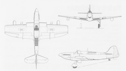
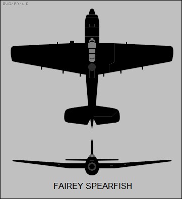
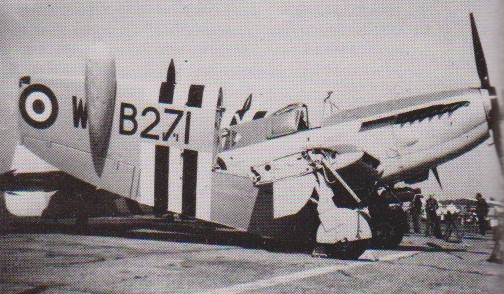
Fairey Spearfish

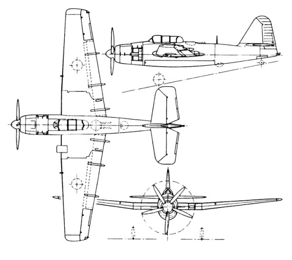
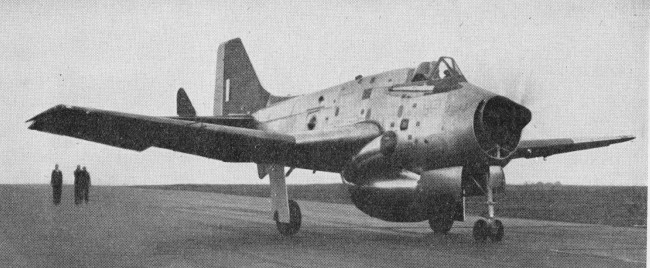
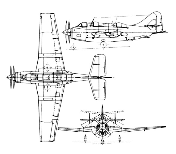
The Spearfish was designed by Fairey Aviation to Admiralty Specification O.5/43 as a replacement for the Fairey Barracuda in the carrier-based torpedo/dive bomber role. In comparison to the Barracuda, the Spearfish had a much more powerful engine, an internal weapons bay and a retractable ASV Mk.XV surface-search radar mounted behind the bomb bay. The Spearfish was half as large again as the Barracuda, as it was designed to be operated from the 45,000-long-ton (46,000 t) Malta-class aircraft carriers then under development.
The Spearfish was a cantilever, mid-wing monoplane, with an all-metal, monocoque fuselage. The centre wing section was built integral with the fuselage and the outer wing panels could be hydraulically folded for carrier operations. A distinguishing feature of the wing was the large Fairey-Youngman flaps that spanned 73.5% of the wing’s trailing edge. The Spearfish had an outward-retracting conventional landing gear with a tailwheel. The wings housed a pair of 183-imperial-gallon (830 l; 220 US gal) fuel tanks, plus a 43-imperial-gallon (200 l; 52 US gal) tank in the leading edge of the starboard wing for a total of 409 imperial gallons (1,860 l; 491 US gal) of fuel. The two-man tandem cockpit had a hydraulically operated canopy.
The large internal weapons bay could alternatively carry up to four 500-pound (230 kg) bombs, four depth charges, a torpedo, or a 180-imperial-gallon (820 l; 220 US gal) auxiliary fuel tank. The Spearfish was intended to carry four 0.5-inch (12.7 mm) M2 Browning machine guns, two in a remote-controlled Fraser-Nash FN 95 barbette behind the cockpit and two in the wings. The only external offensive armament was 16 RP-3 rockets that could be carried underneath the outer wing panels.
In August 1943, the company received an order for three prototypes to be built against Specification O.5/43 and the first prototype, serial number RA356, was constructed at Fairey’s Hayes factory and first flew on 5 July 1945 from Heston Aerodrome; the other two did not fly until 1947. In November 1943 the company was ordered to build a dual-control dive-bombing trainer variant against Specification T.21/43 and this was built at the Heaton Chapel factory and assembled and flown at Ringway on 20 June 1946. Three further development aircraft were ordered in May 1944 to be built at Heaton Chapel, with the last two to be fitted with a Rolls-Royce Pennine engine; only the first Centarus-engined aircraft was built but never flew.
Production orders for 150 aircraft were placed to be built at Heaton Chapel; the first ten aircraft were intended to use 2,600-horsepower (1,900 kW) Bristol Centaurus radial engine, Centaurus 59 engines on the next 22, and Centaurus 60s of the remainder. In addition, the flaps were to be enlarged and lateral control was to be provided by spoilers with small “feeler” ailerons. With the cancellation of the Malta-class carriers, the Fleet Air Arm no longer had a requirement for new torpedo bombers and the programme was cancelled. Work continued on the two other prototypes built at Hayes after the cancellation of the contract, albeit very slowly.
Test pilot Eric Brown evaluated the first prototype and found “the controls in cruising flight were very heavy and, in fact, lateral control was so solid that I could barely move the ailerons with one hand at 130 knots (240 km/h; 150 mph).” In bad weather a pilot circling a carrier while waiting to land would have been forced to fly such a wide circuit that he could not always keep the carrier in sight. The later prototypes had ailerons boosted by hydraulic power and artificial feel to the stick from a spring, as an interim measure but Brown found “the second prototype was much less the pleasant aircraft to fly as the stick continually hunted either side of neutral and there was no build-up of stick force with increase in speed.” The Spearfish lacked any sort of stall warning, which would have been a problem in operational use as the stall and approach speeds were fairly close. For the landing, the aircraft proved quite docile.
The first prototype was later used by Napier & Son at Luton for trials of the firm’s inflight de-icing systems. It was then briefly used for ground-training purposes beginning on 30 April 1952, until it was scrapped shortly afterwards. The second prototype was used by the Royal Navy Carrier Trials Unit at RNAS Ford, Sussex, until it was sold for scrap on 15 September. The third prototype conducted ASV Mk.XV radar trials, but was damaged in a heavy landing on 1 September 1949 and sold for scrap on 22 August 1950 as uneconomical to repair. The fourth prototype never flew and was used as a source of spares. The sole Heaton Chapel-built aircraft was the closest to the planned production configuration and it was used for engine-cooling and power-assisted flying-control trials, until it was struck off charge on 24 July 1951.
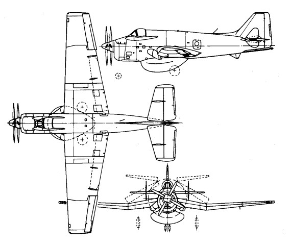
In a follow-up, to meet Specification O.21/44 for a two-seat strike fighter, the Spearfish was redesigned to accommodate a twin-coupled Rolls-Royce Merlin engine and contra-rotating propellers. A variety of other engines were considered and although a production order was placed for three examples in 1944, the programme was eventually shelved, remaining as an unfulfilled paper project.
Engine: 1 x Bristol Centaurus 57, 2,825 hp (2,107 kW)
Propeller: 5-bladed Rotol VH 65, 14 ft (4.3 m) diameter
Wingspan: 18.36 m / 60 ft 3 in
Wing area: 49.24 sq.m / 530.01 sq ft
Length: 13.59 m / 44 ft 7 in
Height: 4.11 m / 13 ft 6 in
Max take-off weight: 10026 kg / 22104 lb
Empty weight: 6901 kg / 15214 lb
Fuel capacity: 409 imperial gallons (1,860 l; 491 US gal)
Max. speed: 470 km/h / 292 mph / 254 kn
Cruise speed: 196 mph (315 km/h, 170 kn)
Service ceiling: 7620 m / 25000 ft
Time to 10,000 ft / 3,048 m: 7.75 min
Range: 1,036 mi / 1,667 km / 900 nmi
Combat range: 349 mi (562 km, 303 nmi)
Armament: 4 x 12.7mm M2 Browning machine guns
Bombload: 1 × torpedo or 2,000 lb (907 kg)
Crew: 2