Aircraft operator, founded by Elmer Faucett, owning airport at Santa Cruz, Lima. Developed aircraft in 1930s for its own airline use and for Huff-Daland Dusters Inc., which it managed. Designs, based on Stinson, included F.19 eight-passenger cabin monoplane. Production discontinued 1947.
Post WW2
Farrington Aircraft
1995-7: 4460 Shemwell Rd, Paducah, KY 42003, USA.
Farrington Aircraft produces the tandem two-seat Model 20A Heliplane cabin autogyro as a modern development of the Air & Space Model 18-A.
1998:
Route 3, Box 319
KY 42001 Paducah
USA
Farrar Flying Wing V-1
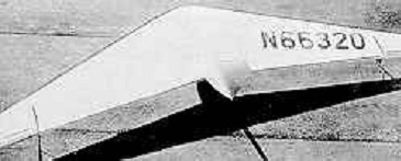
Designed and constructed by Demetrius F. Farrar Jr in 1962, the V-1 Flying Wing was an attempt to create a glider design based on the Northrop Corporation flying wing designs of the 1940s, such as the Northrop YB-49.
The aircraft is made from metal and wood, with doped aircraft fabric covering. Its 26 ft (7.9 m) span wing employs a modified Northrop airfoil and tip-mounted ailerons, in the form of rotating wing tips, of 2 ft (0.6 m) each. A single vertical stabilizer and rudder was mounted at the rear of the wing center trailing edge. The cockpit is located within the wing center section and the pilot flies in the prone position.
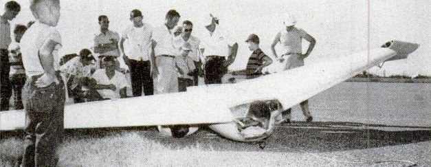
Only one V-1 was built and it was registered with the Federal Aviation Administration in the Experimental – Amateur-built category.
In August 2011 the sole V-1 was still listed on the FAA aircraft register and still owned by the designer, 49 years after it was completed.
V-1
Crew: one
Wingspan: 26 ft 0 in (7.92 m)
Wing area: 90 sq ft (8.36 sq.m)
Aspect ratio: 7.51:1
Airfoil: modified Northrop
Empty weight: 175 lb (79 kg)
Gross weight: 350 lb (159 kg)
Maximum glide ratio: 36:1
Rate of sink: 120 ft/min (0.61 m/s)
Wing loading: 3.89 lb/sq ft (19.0 kg/sq.m)
Water Ballast: 0
No. Built: 1
Farrar Bird Flight Machine
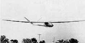
D.J.Farrar Jnrs (USA) design, which first flew in 1969, was sponsored by the National Science Foundation and used at Vanderbilt University in bird flight research, taking advantage of its low operating speed and sink rate. The design goals were a stalling speed of 32 kph/ 17 kt/ 20 mph a 1 fps sink rate. With an aluminum spar, wood and kevlar wing, and a balsa/GFRP sandwich fuselage The airfoil is a helicopter section with a zero pitching moment permitting moderate torsional loads in spite of the large wing area. Despite the low sink rate, the Bird Flight Machine has no approach control aids making landing challenging in most conditions. It was proposed to conduct further exploration of its design capabilities and microlift soaring techniques under the supervision of Gary Osoba.
Wing span: 18.59m / 61ft
Wing area: 21.37sq.m /230sq.ft
Empty Weight: 82kg / 181lb
Payload: 79kg /175lb
Gross Weight: 161kg /356lb
Wing Load: 7.53 kg/sq.m / 1.55lb/sq.ft
Water Ballast: nil
Aspect ratio: 16.18
Airfoil: Wortmann FX-05-H-126
No. of Seats: 1
No. Built: 1
L/DMax: 33
MinSink: 0.32 m/s / 1.05 fps / 0.62 kt
Farner HF Colibri 1 SL
Hans U. Farner was a Swiss aircraft designer whose footlaunched canard ultralight sailplane had briefly reached production in 1966. In November 1974 he filed a patent for a novel control system, particularly suitable for canards. This suggested mounting the canard on a slender tube which slid snugly within a second long forward tube that, together with a pod containing an engine, pilot and bearing mainplanes, formed the fuselage. Extension of the canard-carrying tube by means of fore and aft control column movement increased the canard’s moment arm and increased pitch. The angle of attack of the canard was automatically altered as this happened. Rotating the tube about its long axis by rudder pedal movement turned the canard away from the horizontal and caused yaw, removing the need for a vertical rudder. Wing mounted ailerons controlled roll in the usual way.
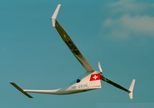
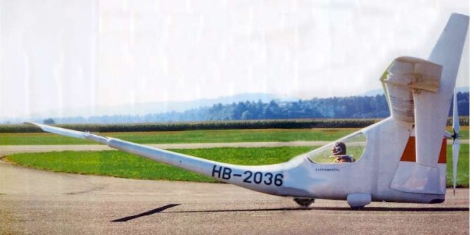
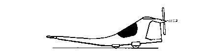
The Farner HF Colibri 1 SL motor glider, designed, built and test flown by Hans Farner in the late 1970s embodied these ideas. It had a very high aspect ratio (31.7) wing with a constant chord centre section carrying dihedral. Outer panels, with anhedral, combined with the inner section to form a cantilever gull wing. Thes outer panels had straight taper on the leading edges only, and rotated as all-moving ailerons or “tiperons” for roll control. The retractable tricycle landing gear is of narrow track limited by the fuselage width, and short wheelbase.
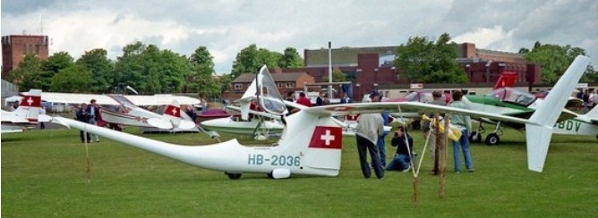
The wing was mounted on top of a narrow fuselage pod, with the pilot under a rear hinged canopy well forward of its leading edge. The Colibri was a twin engined motor glider, with two single cylinder two stroke McCulloch MC-101A, each of 10.1 kW (13.6 hp) driving a two blade pusher configuration propeller via reduction gear and a high positioned shaft, just below and a little way behind the trailing edge. The propeller blades can be folded to the rear when not in use, for soaring flight. Under the drive shaft the fuselage remained deep but tapered rearwards into two door like aerofoils with straight, vertical trailing edges that could be opened symmetrically outwards as an airbrake. Positioned well behind the centre of gravity, they closed together as the only fin. Forward of the cockpit the fuselage curved gently upwards into a tubular, straight, tapering, rising boom. The parallel chord, unswept, high aspect ratio canard, carried on its constant diameter tube in the manner described in the patent, providing lift and both yaw and pitch control. The main gull wing is of very high aspect ratio (31.7) mounted on top of the fuselage at the rear, and unbraced. It has dihedral on the constant chord and constant section (Wortmann FX-61-184) inner panels, and anhedral on the all moving outer panels which have leading edge taper and a Wortmann FX-60-1261 aerofoil section, the same as that of the canard foreplane. No flaps or ailerons are fitted.
The first flight date is uncertain but the Colibri was complete by late 1979. The written record post-1980 is sparse but photographs show it was still flying in 1990, when it appeared at a display in Belgium. It had visited the UK in 1989, coming to the PFA meeting at Cranfield. During the 1980s it had undergone considerable modification to the novel control system, with high aspect ratio, swept fins on the wings first at the outer end of the centre section, just before the start of the rotating tiperons, and then at the wing tips. These images suggest that conventional flight control surfaces were added to both fore and aft wings as well as to the fins. The extensible fuselage also seems to have been abandoned by 1989. It was still flying in 1990.
Engine: 2 × McCulloch MC-101A, 10.1 kW (13.6 hp)
Propellers: 5-bladed pusher foldable
Wingspan: 17.50 m (57 ft 5 in)
Wing area: 9.65 sq.m (103.9 sq ft)
Aspect ratio: 31.7
Airfoil: Wortmann FX-61-184 on centre section, FX-60-126/1 on outer panels
Length: 7.201 m (23 ft 7.5 in)
Height: 1.45 m (4 ft 9 in)
Empty weight: 255 kg (562 lb)
Max takeoff weight: 362 kg (798 lb)
Fuel capacity: 21 L (4.6 Imp gal; 5.5 US gal)
Landing speed: 36 kts / 66 km/h
Initial climb rate: 649.61 ft/min / 3.30 m/s
Maximum glide ratio: 42±1:1 at 101 km/h (63 mph; 55 kn)
Rate of sink: 0.55 m/s (108 ft/min) minimum, at 77 km/h (48 mph; 42 kn)
Take-off run: 120 m (394 ft)
Crew: One
Farner, Hans U
Hans U. Farner was a Swiss aircraft designer whose footlaunched canard ultralight sailplane had briefly reached production in 1966. In November 1974 he filed a patent for a novel control system, particularly suitable for canards. This suggested mounting the canard on a slender tube which slid snugly within a second long forward tube that, together with a pod containing an engine, pilot and bearing mainplanes, formed the fuselage.
In November 1976, the team moved to an old mill in Wald (Switzerland). In February 1977 Ernst Ruppert, Hans Farner and Heinrich Bucher (who provide the funds) set up Aviafiber AG, with a view to marketing Canard 2FL. In the same year, the company became Canard Aviation AG after an agreement with the Avia oil company.
The inaugural flight took place on 13 August 1978. Subsequently, numerous other flights were carried out, totaling about 60 hours, and improvements made.
The HF 1-SL Colibri canard designer was Dipl-Ing Hans U Farner, a professor at Universität Zürich. Aerodynamicist Hans Farner was killed testing Canard 2FL HB-3000 in 1980. His Canard 2FL, Canard SC, and Canard SCM designs were then withdrawn from the market by his financer and business partner, Heinrich Bucher.
Farm Aviation Ltd
UK
Revived program initiated by de Havilland Aircraft in 1958 to convert Chipmunk primary trainers for agricultural use. Three machines converted for the company’s own use, followed by others for agricultural aircraft operators.
Falconar Teal
The Falconar Teal was a two-seat homebuilt, amphibious airplane designed by Chris Falconar of Edmonton, Alberta, Canada.
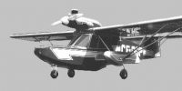
The Teal was based on the two- or three-seat AMF Maranda, and was built mostly of wood. It featured strut-braced high wing, with “W” configuration struts running from the wing roots, down to stabilizing floats (which also contained the main wheels), then back up the wings near 70% span; cruciform tail; two pilots seated side by side under the wing; access to the cockpit by side doors; tricycle undercarriage with the main wheels retracting into stabilizing floats only about 25% of the wing span. The nosewheel retracted into the bow and was covered by two conventional (side-hinged) doors. A rarity among flying boats was its engine location in a nacelle, above the wing, with the propeller rotating immediately in front of the windscreen.
The Teal was first flown in December 1967.
From the 1970s to the 1990s plans were sold by Falconar Aviation of Edmonton (downtown municipal airport). A handful were built by amateur aircraft constructors (aka homebuilders) in Canada and the United States. Most were powered by certified Lycoming or Continental engines.
Engine: 1 × Lycoming O-320-B2A, 160 hp (120 kW)
Wingspan: 33 ft 0 in (10.06 m)
Wing area: 160 sq ft (15 sq,m)
Airfoil: NACA 4412 (modified)
Aspect ratio: 6.6:1
Length: 24 ft 6 in (7.47 m)
Height: 7 ft 10 in (2.39 m)
Empty weight: 1,050 lb (476 kg)
Max takeoff weight: 1,500 lb (680 kg)
Maximum speed: 130 mph (210 km/h, 110 kn)
Cruise speed: 125 mph (201 km/h, 109 kn) (max cruise)
Stall speed: 37 mph (60 km/h, 32 kn)
Never exceed speed: 185 mph (298 km/h, 161 kn)
Range: 450 mi (720 km, 390 nmi) standard fuel
Ferry range: 700 mi (1,100 km, 610 nmi)
Service ceiling: 16,400 ft (5,000 m)
Rate of climb: 1,100 ft/min (5.6 m/s)
Crew: 1
Capacity: 1 passenger
Falcon Aircraft B-350 / B-360 Falcon De Luxe Brigadier
The Baumann Brigadier, re-engined with two 175 hp Continental engines to become B-350 or B-360 Falcon De Luxe Brigadier.
Falcon Aircraft Manufacturing Co
USA
Established 1958 to acquire engineering and production rights to Baumann Brigadier, re-engined with two 175 hp Continental engines to become B-350 or B-360 Falcon De Luxe Brigadier.
