As he worked on the Dragonfly, Mitchell set out on his own to build a new flying wing glider, which he called the Osprey, a single seat machine fitted with stabilators. Mitchell tested his flying wing several times near Oakland, in 1950. Unfortunately, the building in which the glider was stored burned to the ground and the flying wing was destroyed.
Post WW2
Mitchell B40F
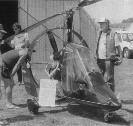
A hang gliding fanatic, Dr H Long, gave Don Mitchell control of a high performance wing. By 1975 this same wing had become the B 10. The first powered version now carries the designation of B40F (F for foot launch).
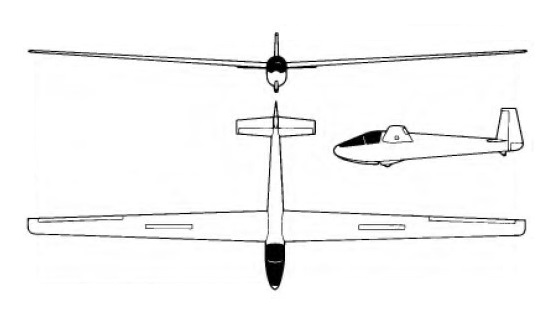
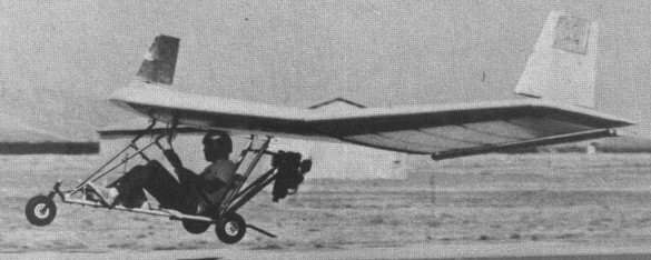
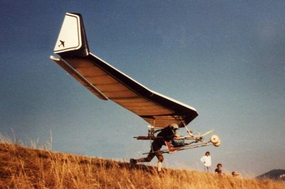
The aircraft is in effect a wing, supporting beneath its lower surface a rigid frame formed by two sets of struts in the shape of an N, at the back of which is mounted a McCulloch Mc101 12hp engine with direct drive to a two blade pusher propeller.
The addition of a go-kart engine and streamlined pilot pod has turned the design into a high-performance ultralight. It is fast, sensitive and very maneuverable. The wing is wooden and built up in a typical “D” Section cantilever, with pilot cage attached underneath and a pusher prop in the rear. Top speed is about 55 mph, and climbout is around 350 fpm. It can be foot-launched, but the added weight of an engine and its accessories make it wise to consider tricycle gear. A Mac 101 engine swings a 42-inch prop and sips two gallons of gas in two hours.
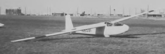
Mitchell Wing

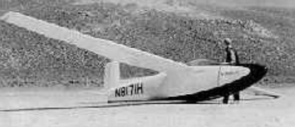
A hang gliding fanatic, Dr H Long, gave Don Mitchell control of a high performance wing. It has aerodynamic control of external “stabilator” surfaces about all three axises through the use of a joystick. No weight shift is required. Spoilers are used to initiate a turn or to steepen the glide path for landing. Its extremely flat glide and low sink rate allow it to takeoff and land in almost ‘no wind’ conditions.
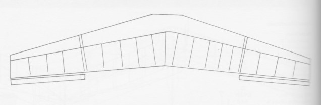
The wing is an all-wood structure with foam leading edge ribs. It has a single built-up C-spar with aircraft birch plywood torsion proof leading edge. The built-up truss ribs aft of the spar ar covered with seconite fabric.
The 8 ft 6 in outboard wing panels fold up over on top of the centre section for transportation. They may be removed as three pins connect outboard panels to the centre section.
The pilot is housed in a metal cage below the wing. Spoiler control is on the left, the control stick on the right. In flight the pilot goes into the supine position. A large clear mylar covering on the trailing edge above the pilot gives visibility overhead. The pilots cage folds up for ease in transportation.
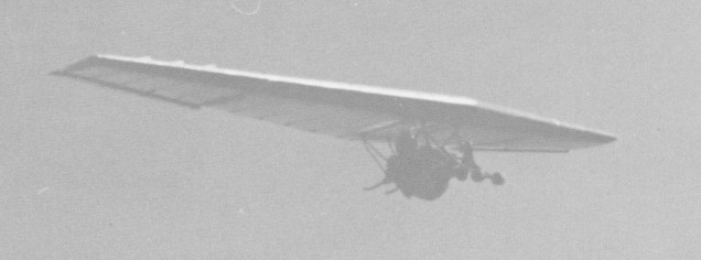
In 1977 George Worthington flew an unpowered Mitchell Wing a straight distance of 107.8 miles.
By 1975 this same wing had become the B 10. The first powered version now carries the designation of B40F (F for foot launch).
The Mitchell was a rigid hang glider in wood, sold in plans. Two American companies were selling the rigid Mitchell. U.S Pacific sells plans and wood kits while Ameriplanes sells aluminium kits.
The 1976 wing was for advanced pilots. At lrast 20 service bulletins were to be applied to be safe.
Very pleasant in flight despite the strong reverse yaw but stable. The first 2 minutes are crucial because you have to understand everything quickly, the reverse yaw, the use of the rudders and the sensitivity of the handle on the pitch.
Wing area: 12.64 m²
Wing span: 10.2 m
Aspect ratio: 8.4
Hang glider weight: 35 kg
Minimum speed: 30 km/h
Maximum speed: 120 km/h
Max glide ratio (L/H): 16
Max glide ratio speed: 55 km/h
Minimum sink rate: 0.6 m/s
Wingspan: 10.36m
Wing area: 12.63m²
Weight: 37 kg – 39 with updates
VNE 120 km / h
Max. 100 km / h
Min speed: approx 30 Km / h
Max glide ratio (L/H): 16-18
Load: +6 -6G in free flight version (+4 -4 in ULM version)
Min fall rate: 0.6 – 0.8 m / sec
Wing span: 34 ft
Wing area: 136 sq,ft
Aspect ratio: 8.4
Weight: 68 lb
Takeoff speed: 14 mph
Stall speed: 11 mph
Max speed: 50 mph
Best glide ratio (L/D): 18-1
Best L/D speed: 32 mph
Min sink: 108 fpm
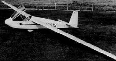
Mitchell Nimbus
The Nimbus III was developed in 1956 by Don Mitchell from the earlier I and II models. Mitchell produced nine kits, of which four were completed. The prototype Nimbus III has a Gottingen airfoil and considerably less performance.
Nimbus III
Wing span: 12.19 m / 40 ft
Wing area: 9.85 sq.m / 106 sq.ft
Empty Weight: 204 kg / 450 lb
Payload: 100 kg / 220 lb
Gross Weight: 304 kg / 670 lb
Wing Load: 30.86 kg/sq.m / 6.4 lb/sq.ft
Aspect ratio: 14.7
Airfoil: Wortmann FX-05-191
L/DMax: 39 106 kph / 57 kt / 66 mph
MinSink: 0.73 m/s /2.4 fps / 1.42 kt
Seats: 1
Structure: all-wood, 3-piece wing
Mitchell
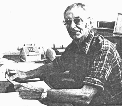
The Mitchell family of aircraft began in 1915, in Scotland, with the birth of Donald S. “Don” Mitchell. Hoping to create a better life for themselves, the family immigrated to the United States when the boy was only seven years old. He was still in school when he became fascinated with gliding. Indeed, Mitchell was a student at Alameda High School in Alameda when he built his first glider, under the tutelage of a pilot who had seen action during the First World War.
Intent on pursuing a career in aviation, Mitchell enlisted at the Boeing School of Aeronautics in Oakland.
In the 1930s, Mitchell worked for United Air Lines at Oakland and Fresno as a radio operator and station attendant. By now, however, he only dreamt of gliding. In spite of the Depression, Mitchell left his job in order to move south to San Fernando, near Los Angeles, where he visited glider pioneer William H. Bowlus – shop foreman at the factory which built Charles Lindbergh’ Spirit of St. Louis – and all but begged him to teach him how to design and build gliders.
Bowlus accepted and Mitchell trained under him for the next six years. All in all, Mitchell spent eleven years with Bowlus, working as his right-hand man on numerous projects during his last five years with his mentor. Along with another gentleman, the duo founded Bowlus Sailplane toward the end of 1936 and developed the BA-100 Baby Albatross glider, a very popular design with some structural problems, which was sold mainly if not exclusively in kits.
As the 1940s began, Mitchell designed and started to construct a large two-seat flying wing glider. To keep it under control without the usual tail, he developed a combination of aileron and elevator which he called a stabilator. All the while, Mitchell took part in demonstration flights for Bowlus Seaplane and was appointed soaring editor of Western Flying Magazine.
When he finally left Bowlus Sailplane, Mitchell went to teach aircraft welding at a technical institute located close by, at the Grand Central Air Terminal near Glendale. Leaving this position, he moved another short distance to the new Timm Aircraft factory in Van Nuys, where he helped with the molding of the fuselage of the S-160, a plastic-bonded wood basic trainer developed for use by the U.S. Navy and U.S. Army Air Corps. Mitchell later assisted the Civil Aeronautics Administration when the time came to perform the static tests of the aircraft. It passed with flying colours and later became, in April 1941, one of the first if not the very first ever plastic-bonded aircraft to receive an American Approved Type Certificate. The S-160 was later ordered by the U.S. Navy. Approximately 260 of these airplanes – now designated Timm N2T Tutors – were produced.
In early 1942, Timm Aircraft was awarded a U.S. Army Air Forces (USAAF) contract to build Waco CG-4 cargo gliders. Many other American companies received orders as well. Timm Aircraft eventually built close to 450 CG-4s. This aircraft turned out to be the most widely produced cargo glider in history.
His superiors at Timm Aircraft instructed Mitchell to organise construction of CG-4A wings in the factories of two furniture makers of the Los Angeles area. Weber Showcase, one of these manufacturers, soon hired him to take over control of their production. As all this was taking place, Mitchell nonetheless found the time to spend numerous evening and weekends with Bowlus to help with the design and construction of a pair of gliders – quite possibly two military transport gliders which proved eventually faulty under test and failed to win orders – as well as a half-size prototype of a large and rather unusual-looking transport glider designed as a private venture for the USAAF.
Confident that his design could help the war effort, Bowlus and an associate organised a company which finally became General Airborne Transport. Construction of a full-size prototype capable of carrying 42 soldiers or 10,000 pounds of freight, began. Mitchell left Weber Showcase in the spring of 1943 to work on this glider, all the while spending some time on his own flying wing design. Mitchell apparently became Director of Projects at General Airborne Transport. Sadly, the prototype of the CG-16 crashed in September 1943 during a test flight. Only Bowlus and one of the VIP passengers managed to parachute to safety. Still, the company managed to obtain permission to build a second prototype. An imposing-looking machine with good flying characteristics, the CG-16 nonetheless suffered from a number of design flaws. The program was cancelled in late 1944 and a third airplane was not built.
Following the end of the CG-16, Bowlus and a friend, Ted Nelson, started to work on a motorised version of the BA-100 Baby Albatross glider. The two of them formed Nelson Aircraft in San Fernando (California) to meet a perceived need for powered gliders now that the Second World War seemed about to end. Mitchell, who may helped with the design of the airplane, the Nelson Dragonfly, took part in the Civil Aeronautics Administration certification tests. Bowlus later appointed him supervisor of production.
In April 1946, after some years of work, Mitchell finally completed construction of his flying wing glider. After a number of successful test flights, Mitchell mounted a small engine on it and flew it as a powered airplane. In the meantime, the expected postwar light airplane boom was slowly turning into a bust and only a handful of Dragonflies left the factory. When the company closed its doors, Mitchell moved to San Leandro where he worked with Nelson and an associate on the design of new powered gliders. Their 1949 Nelson Hummingbird proved to be a better performer than the Dragonfly but its cost and relative lack of performance doomed it on the market. Only a handful were built.
As he worked on the Dragonfly, Mitchell set out on his own to build a new flying wing glider, which he called the Osprey, a single seat machine fitted with stabilators. Mitchell tested his flying wing several times near Oakland, in 1950. Unfortunately, the building in which the glider was stored burned to the ground and the flying wing was destroyed.
Faced with this, Mitchell threw himself into the design and construction of the Nimbus series of sailplanes. The Mitchell Nimbus III – which was developed around 1956 from the earlier Nimbus I and II – won the High Performance Sailplane Design Award at the 23rd National Soaring Contest held in Texas, as well as an award at the San Diego soaring meet.
During much of the 1960 and early 70s, Mitchell kept himself occupied by repairing and customising a number of aircraft. Around 1974, as interest in hang gliding was rapidly increasing, a Dr. Howard Long became intrigued by the idea of a flying wing hang glider. He asked Mitchell to build him such an aircraft. The first foot-launched Mitchell Wing hang glider, the first rigid-wing hang glider that could be controlled in roll, pitch and yaw, flew in 1976. Its flying characteristics and performance showed such promise that Mitchell received orders to build twelve after just one public demonstration flight.
Fascinated by the idea of capturing all the official records for hang gliding newly recognised by the Fédération aéronautique internationale, American champion sailplane pilot George Worthington bought the third one built and went on to set half a dozen world records between 1976 and 1981. Interest among enthusiasts was such that Mitchell organised Mitchell Wing – later Mitchell Aircraft – at Porterville (California). Orders came in from all over North America, Europe and beyond.
In the mid 1970s, Mitchell added a tubular structure and a small engine on one of his wings, turning it into a powered glider or ultralight airplane. A prototype first flew in 1976. The new powered model gained fame as the Mitchell B-10. Mitchell took his flying wings to the world famous fly-ins at Oshkosh and was awarded top honors on numerous occasions.
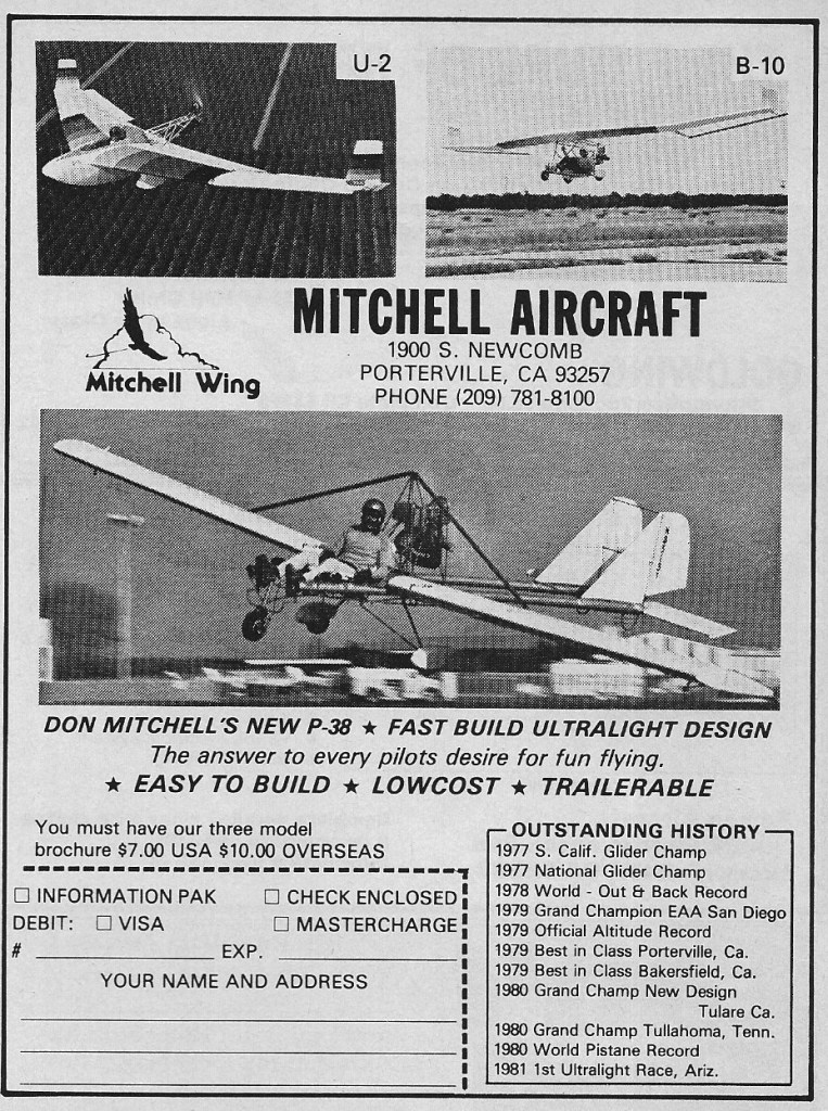
Design and construction of the U-2, an ultralight fitted with an enclosed nacelle for the pilot followed in 1979. In 1983, a Mitchell U-2 set a new world altitude record for aircraft weighting less than 270 kg with a climb to about 26,000, as well as a sustained altitude record of slightly less than 26,000 ft. The Mitchell P-38 flew later on.
1983: Mitchell Aircraft Corp, 1900 South Newcomb, Porterville, California 93257, USA.
1984: 11616 W. 59th Street South, Sand Springs, OK 74063, USA.
Over the years, Mitchell has sold hundreds of drawings and kits for the B-10, the U-2, the P-38 as well as the hang gliding version of the B-10. The designations Mitchell gave to his creations were those of great American aircraft, i.e. the very modern Martin B-10 bomber of the 1930s, the highly distinctive Lockheed P-38 Lightning fighter of the Second World War and the famous Lockheed U-2 spy plane of the Cold War era.
Don Mitchell took ill and died in 1993.
Mississippi State University XV-11 Marvel
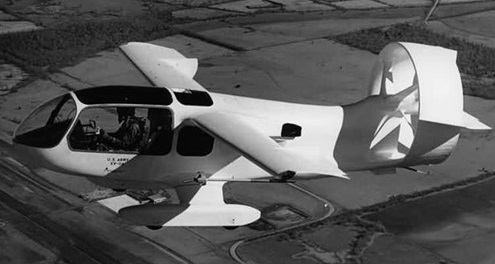
Students and researchers at Mississippi State University in Jackson built and flew the XV-11 Marvel in 1965 to test boundary layer and STOL technology. The name M.A.R.V.E.L. stood for “Mississippi Aerophysics Research Vehicle with Extended Latitude”.
The first all-composite aircraft, it carried out its initial program of research on behalf of the US Army in the late 1960s, and was rebuilt in the 1980s as a proof-of-concept for a utility aircraft.
The Marvel is now on permanent display at the Southern Museum of Flight at the Birmingham International Airport in Alabama.
Minty Special Skyhook
Ted Minty designed Skyhook single-seat light autogyro, first flown 1978.
Millet-Lagarde ML-10
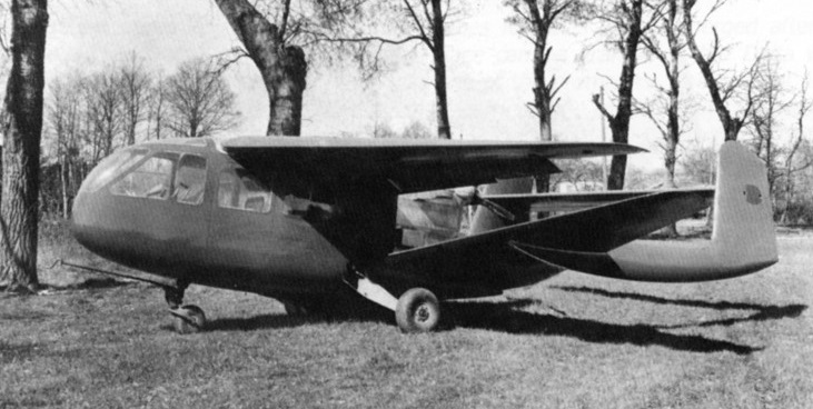
A twin-boom, heavily-staggered biplane four-seater, powered by 180 hp Regnier engine and first flown 1949.
Millet-Lagarde
France
Formed by Mm. Millet and Lagarde to exploit Lagarde ‘s ML-10 twin-boom, heavily-staggered biplane four-seater, powered by 180 hp Regnier engine and first flown 1949.
Miller Tern
The Tern high perfomance single-seater was designed by Mr W. Terry Miller of Furlong, Pennsylvania, for amateur construction and the prototype, which was built in a total of 1,180 working hours, made its first flight in September 1965.
An improved version, known as the Tern II, made its first flight in August 1968; this featured a wing span increased by 4 ft 6 in to 55 ft 6 in, increasing the aspect ratio from 20 to 22, and giving an improved best glide ratio and minimum sinking speed. During 1968 brake parachutes were fitted to the prototype Tern, and two types of these were later made available for installation in both versions of the Tern in the base of the rudder, namely a 6 ft diameter cross parachute or a 5 ft diameter guide surface parachute.
By May 1970 nearly 100 Terns and 12 Tern IIs were under construction not only in the USA, but by amateurs in Africa, Australia, South America and Canada.
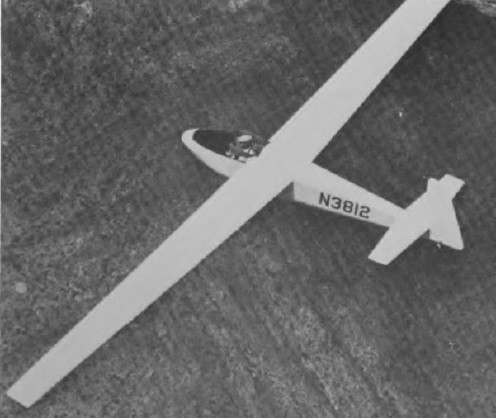
Of conventional all-wood construction, the Tern has unswept cantilever shoulder wings which are two piece two-spar spruce structures, entirely plywood covered. There are no flaps and the plain ailerons are also all wood; there are wooden spoilers in the wing lower surface used for approach and glide slope control. The semi-monocoque wooden fuselage has a plastic-reinforced glassfibre nose and plywood skinning aft of the cockpit. The cantilever all-wood tail unit has modified NACA laminar flow sections and special hinge-line contours to reduce drag and increase control effectiveness at large angles of deflection; there are no elevator or rudder tabs. Landing gear consists of a non-retractable monowheel forward of the eg housed in a streamlined pod, and skids under the nose and tail; there is a brake lever for applying pressure directly to the tyre. The pilot sits in a semi-reclining seat under a three piece canopy, the centre portion of which hinges sideways for entrance and exit, and radio can be fitted.
One Tern belongs to the National Soaring Museum.
Tern
Wing span: 15.54 m / 51 ft
Wing area: 12.08 sq.m / 130 sq.ft
Empty Weight: 215 kg / 475 lb
Payload: 102 kg / 225 lb
Gross Weight: 317 kg / 700 lb
Wing Load: 26.24 kg/sq.m / 5.4 lb/sq.ft
L/DMax: 34 93 kph / 50 kt / 58 mph
MinSink: 0.64 m/s / 2.1 fps / 1.24 kt
Aspect ratio: 20
Airfoil: Wortmann 61 Series
Seats: 1
Tern II
Span: 15.56 m / 55 ft 6 in
Length: 6.49 m / 21 ft 3.5 in
Height: 1.52 m / 5 ft 0 in
Wing area 13.01 sq.m / 140 sq ft
Aspect ratio: 22.0
Wing section: Wortmann 61 Series
Empty weight: 249 kg / 550 lb
Max weight: 363 kg / 800 1b
Water ballast: None
Max speed: 120 mph / 104 kt / 193 km/h (smooth air)
Stalling speed: 34.5 kt / 64 km/h
Max aero-tow speed: 88 mph
Max rough air speed: 76.5 kt / 142 km/h
Min sinking speed: 1.95 ft/sec / 0.59 m/sec at 48 mph / 41.5 kt / 77 km/h
Best glide ratio: 38:1 at 60 mph / 52 kt / 97 km/h