Developed to USAF General Operational Requirement 38 for an intercontinental bomber to replace the Boeing B-52.
At one time the order was cut back to a single prototype containing no military equipment. In 1960 the US Government decided to order 12 fully operational B-70s. In March 1961, the contract awarded on 4 October 1961 was again cut back to three aeroplanes, intended mainly for research, although the third was later cancelled.
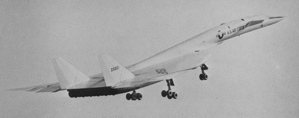
The North American XB-70 Valkyrie first flew in prototype form on 21 September 1964. When the first prototype flew it was simultaneously the longest (56.4 m/185 ft), fastest (Mach 3+), most powerful and costliest aircraft ever built, US$2000 million, and weighing 305 tonne (300 ton). Piloted by North American test pilot Alvin S. White and USAF Col. Joseph F. Cotton the first take-off took a 5000 ft ground roll and 30 seconds to get airborne. During the 65 min flight from Palmdale to Edwards Air Force Base the main wheels failed to retract and number three J93 GE engine over-revved. The aircraft flew to 16,000 ft and 375 mph. Locked rear wheels on the left main gear ground themselves down to metal on touch-down.
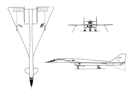
A delta-winged canard design, the airframe made extensive use of contemporary ‘exotic’ alloys to overcome the problems associated with kinetic heating. The wings were swept back at 65 degrees 34 minutes on the leading edge, and were covered with brazed stainless steel honeycomb panels welded together to produce an extremely strong yet heat-resistant whole. Similar construction was used for the huge rectangular moveable engine duct under the centreline, the twin vertical tail surfaces (30 ft high) and part of the fuselage. The advanced aerodynamics of this elegant yet menacing warplane were based on a large delta wing from whose centre grew a slim forward fuselage complete with canard foreplanes.
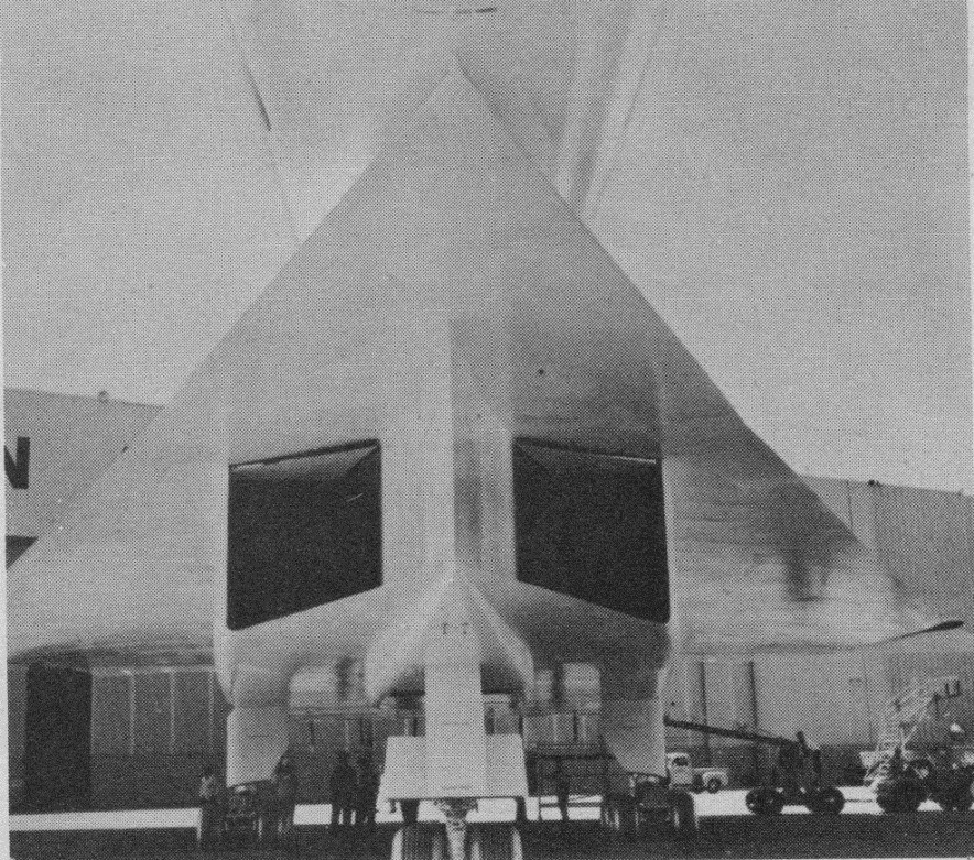
The powerplant comprised six 31,000-lb (14.062-kg) thrust General Electric YJ93-GE-3 afterburning turbojets in a 30 ft long ducted arrangement under virtually the full chord of the delta wing. To slow entering airstream from Mach 3 to less than Mach 1 the designers created a series of shock patterns which employ the vertical splitter, then additional breaks within the splitter duct. Finally hydraulically operated panels vary final throat area to meet varying conditions.
The wings outer portions were arranged to hinge downward in flight under hydraulic power to improve stability and maneuverability. An anhedral angle of 25 degrees was used for low-altitude supersonic flight, increasing to 65 degrees for high-altitude flight at Mach 3. Six power hinge actuators on each lower outer surfaces during high speed flight. Each hinge has hundreds of closely meshed gears of hard H-11 steel.
Control was provided by a combination of flaps on the canard foreplanes, no fewer than 12 wide-chord elevons across much of the trailing edge of the wings outboard of the variable-geometry engine exhausts, and large rudders on each of the vertical surfaces. The canard slab surfaces provide trim control while keeping drag low, their rear section deflecting down as flaps. Control of so complex an aerodynamic platform moving at high supersonic speeds was effected with the aid of a three-axis stability-augmentation system.
The landing gear consists of 2 tons of wheels, tires and brakes. A brake control device employs a fifth wheel on the main gear, comparing the amount of slippage between braked wheels and the fifth wheel with coefficient of friction between tires and runway surface, predicts skid point, and automatically regulates
The windshield moves along with a variable-position nose ramp. During subsonic operation the forward edge of the windshield can be lowered for better visibility. Dark spots above the cockpit area and on the canard surfaces are crane lift points.
The first prototype was flown by Alvin S. White and Colonel Joseph F. Cotton on 21 September 1964. The take-off from Palmdale runway required 5000 ft and less than 30 sec roll. During the flight the undercarriage failed to retract, one of the six engines failed, and a brake locked which burned out half of the left main gear supports. The flight was held to a maximum of 375 mph and 16,000 ft for the flight of just over one hour.
The first flight had been so long postponed and the entire project downgraded to only two prototypes. By the flight, the first US had spent $1.34 billion on its development. $92 million was then allocated to see the two prototypes through the flight program. Both XB-70’s were programmed for a 180 hr flight test schedule, including experiments for NASA. It first achieved its design speed of Mach 3 on 14 October 1965.
NASA’s Flight Research Center spent $2,000,000 on instrumentation on the No.1 aircraft. Areas of study included flutter of skin panels and internal noise levels; heating of structures in such areas as windshield, fuel tanks and crew compartment.
The improved second prototype flew on 17 July 1965, but was lost in a mid-air collision on 8 June 1966. The surviving aircraft carried out a number of test programmes, including work in connection with the US supersonic transport programme, but on 4 February 1969 it was flown to retirement at the US Air Force Museum, Wright Patterson AFB, Dayton, Ohio.
Even before the first prototype flew, however, technological developments in air defence had made the XB-70 obsolete. In 1963 the U.S. government ended the XB 70 development programme and turned the prototypes over for research purposes although one of the XB 70s was lost on 8 June 1966. The surviving XB 70 is now a museum piece.
Engines: 6 x General Electric YJ93-GE-3 afterburning turbojets, 31,000-lb (14.062-kg) Wing span: 105 ft 0 in (32 m) Length: 196 ft 0 in (59.74 m) Max TO wt: 530,000 lb (240,400 kg) Max level speed: M3 / 3218 km/h / 2000 mph Height: 9.1 m / 29 ft 10 in Wing area: 565.0 sq.m / 6081.60 sq ft Ceiling: 21336 m / 70000 ft Range w/max.fuel: 12000 km / 7457 miles Crew: 2
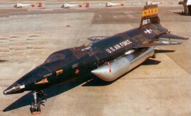
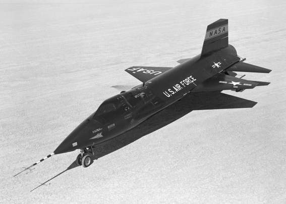
The X-15 was a hypersonic research aeroplane, a rocket-powered type air-launched by an adapted B-52 bomber within a programme that yielded important results in flight at very high speed and extreme altitudes. The objective was an aeroplane capable of flying at 4,500 mph (7,240 km/h; nearly Mach 7) and reaching an altitude of 250,000 ft (76,200 m). North American Aviation won the design contest and was awarded a development contract on 30 September 1955.
The aircraft was designated X 15 and was designed around a Thiokol (Reaction Motors) XLR99-RM-2 single-chamber throttleable XLR99 liquid-¬fuel rocket engine capable of delivering a thrust of more than 60,000 lb (27,215kg) for a period of several minutes. Like X 1, the X 15 was to be air launched, since fuel could not be expended in getting the X 15 off the ground and up to operating altitudes.
The X-15 was built largely of titanium and stainless steel, covered mostly with a so-called ‘armour skin’ of Inconel X nickel steel alloy to withstand temperatures ranging from 1200 deg F to –300 deg F, with heating rates of 30 BTU per sq ft of surface area per second. Far higher temperatures were recorded by the X-15A-2 after this type had been fitted with Emerson Electric T-500 ablative material to provide a capability for comparatively steep (and therefore high ¬friction) angles of re-entry after apogee in the interface between the troposphere and space. This capability to operate on the edges of space demanded a reaction control system for orientation of the aeroplane in these virtually airless regions: a rocket system was used for this stem, with four nozzles in the wingtips and eight more nozzles in the nose to provide three-dimensional manoeuvre capability.
Two Boeing B 52s were modified as carriers for the X 15s, three of which were ordered. With a span of only 22 ft (6.70 m) for the slightly swept¬back trapezoidal wings the X 15 had a gross weight at launch of over 31,000 lb (14,060 kg), of which more than 18,000 lb (8,165 kg) was accounted for by the liquid oxygen and anhydrous ammonia rocket propellants.
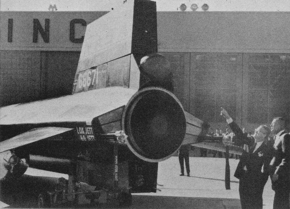
In September 1957, the first one rolled out of the factory. Six months later, in March 1959, the X-15 made its first captive flight and, three months after that, its first glide flight.
When the first X 15 free flight was made on 8 June 1959 the aircraft was fitted with lower powered engines, as the XLR99 was not then ready. Carried aloft by an NB-52, the X-15 was piloted by Scott Crossfield. With two XLR11 RM 5s, giving a combined thrust of about 33,000 lb (15,000 kg), the first powered flight was made by the second X 15 prototype (56-6671) on 17 September 1959, a speed of Mach 2.11 and altitude of 52,341 ft being achieved. From that point on, both the speed and the altitude reached by the X 15s climbed steadily, with Mach 3 being reached in November 1961 after the XLR99 engine had been fitted in the second prototype. By December 1963 the X 15s had reached a speed of Mach 6.06, had encountered a skin temperature of 1,320 degrees F and reached an altitude of 314,750 ft (95,936 m).
In June 1959, in the X-15s very first free flight, Crossfield’s landing was a little touchy due to the pitch damper failure and pilot-induced oscillation.
On 17 September 1959, Scott Crossfield took the X-15 through the paces of its first powered flight. In its second powered flight three months later, also flown by Crossfield, the vehicle’s nose gear door failed due to a rough landing on Rogers Dry Lake. According to the official report, the structural failure occurred on landing “due to design flaw and excessive propellant weight,” but the NASA engineers at Edwards knew otherwise and North American then adopted the special approach theory for landing. This involved a 360 degree spiralling descent starting at about 40,000 ft, right above the desired touchdown point on the runway. From that ‘high key’ position, the pilot moved into a 35 degree bank (usually to the left) while maintaining an airspeed of 285-345 mph. At roughly 20,000 ft after some 180 degrees of the spiral had been completed, the X-15 reached the ’low key’. At this point, the aircraft was headed in the opposite direction of the landing runway and was about four miles abeam of the touchdown point. From the low key, the turn continued through the other 180 degrees until X-15 lined up with the runway at about a five mile distance. The rate of descent through the spiral averaged over two miles per minute, which meant it took on average about three minutes to go from high key to that point where the X-15 was ready to head straight for landing.
Neil Armstrong’s second X-15 flight, and his first for research purposes, came just before noon on Friday 9 December 1960, also in the number one airplane. Flight 1-19-32 first tested the X-15’s newly installed ‘ball nose’. Until this flight, the X-15 had a front mounted boom with vanes to sense airspeed, altitude, angle of attack, and angle of sideslip in a free aerodynamic flow field. At such high altitudes and high speeds, the X-15 would melt its nose boom, destroying measurement data. The ball nose sphere could be cooled from the inside by liquid nitrogen.
Equidistant from the circumference were sensor ports in the middle of the ball as well as on the top and bottom. The ball moved automatically in pitch and yaw to keep the pressure equal on both of the ports, pointing the centre hole directly into the free flow. The angle of the ball movement amounted to the airplane’s angle of attack. Similarly, the ball nose received precise indications of angle of sideslip and dynamic pressure, which then gave airspeed.
Flight 3-4-7 piloted by Neil Armstrong on 5 April 1962, reached Mach 4.12 and 180,000 ft to test the MH96 reaction controls. The test flight spanned 181.7 miles in a little over 11 minutes before landing at Rogers Dry Lake. Flight 3-4-8, on Friday 20 April 1962, by Neil Armstrong, was to test the MH-96 system limit, or ‘g limiter’, to prevent the pilot from exceeding 5g. The flight reached 207,500 ft. Ballooning creates some control problems at the altitude and made an extended trip back. Neil Armstrong’s X-15 flight on 27 June 1962 resulted in the highest Mach number every attained in the X-15 program – Mach 5.74 or 3989 mph.
North American X-15 No.2, damaged in November 1962 in a hard landing at Mud Lake, Nevada, was completely rebuilt, ready to fly in May 1964. Most noticeable difference in X-15-2 from other models is the addition of two 22 ft fuel tanks of 38in diameter on the lower sides of the fuselage. Carrying liquid hydrogen and anhydrous ammonia, they extend burning time of the Thiokol 58,000 lb thrust YLR-99 rocket engine from 88 seconds to 146 seconds. With additional length of powered flight X-15-2 should top previous marks of 4104 mph and 354,200 ft altitude. Both set by NASA Chief Test Pilot Joe Walker.
The tanks drop off when the plane reaches Mach 2, are recoverable by parachute. Extra fuel, weighing 13,500 lb, plus other modifications, bring X-15-2’s take-off weight to 25 ton, eight ton more than the others.
The outer half of the right wing is detachable so that various structural material can be tested in flight. The plane will carry a ramjet engine slung from the tail to test hypersonic airbreathing propulsion. Liquid hydrogen ramjet fuel is stored in two internal tanks.
Cameras have been installed for ultra-violet star photography at altitude above 40 miles, beyond the ozone layer which filters out most ultra-violet rays.
The fuselage is 29in longer than other X-15’s, nose and main landing gear has been lengthened to 39.5in ground clearance, oval windshields installed to withstand higher temperatures, and ablative material added to skin surfaces to suppress heating of the basic structure.
Projects to be performed by all three X-15’s were expected to require another 100 flights running well into 1968.
The X-15A-2 propulsion system is Thiokol Chemical’s Reaction Motors Division’s YLR99 rocket engine. Even its 58,000 lb thrust can be upped through externally-mounted ramjet engines. The YLR99 operates on liquid oxygen and anhydrous ammonia which is fed into the thrust chamber by a turbopump driven by hydrogen peroxide. The ball above the engine exhaust chamber (tail slot) will contain pressurised helium which will be used to expel liquid hydrogen fuel in testing of the ramjet engines.
X-15A-2
In an experiment in 1964, an X-15 attempted a photo mission from 100,000 ft while speeding at 3290 mph over Edwards AFB (Calif). The purpose was to determine effect on camera and film of extremely high temperatures encountered at that speed, and clarity of photos for reconnaissance use.
With Major William J. “Pete” Knight at the controls, the modified X-15A-2 set an unofficial speed record of 4,520 mph (Mach 6.70) on 3 October 1967. This would be the fastest flight of the X-15 program.
X-15A-2
Before the end of 1961, the X-15 had attained its Mach 6 design goal and flown well above 200,000 feet; by the end of 1962 the X-15 was routinely flying above 300,000 feet. The X-15 had already extended the range of winged aircraft flight speeds from Mach 3.2 to Mach 6.04, the latter achieved by Bob White on 9 November 1961.
On 9 November 1962, the second X-15 crashed while executing an emergency landing on Mud Lake near Edwards AFB. Pilot Jack McKay was seriously injured but later returned to flight status. The X-15 itself was nearly a write-off, but eventually the Air Force and NASA decided to rebuild it to a slightly different configuration. The fuselage was lengthened 29 inches and external drop tanks were added to accommodate additional propellants. It was hoped this would allow the X-15A-2 to achieve at least Mach 7 while testing experimental scramjet engines. This first flew on 28 June 1964. On 22 August 1963 Joseph A. Walker, NASA test pilot, took the o.3 X-15 for a world altitude record of 351,000 ft. It was the fifth flight into space for the plane and the third for Walker. He covered 315 miles in 10 minutes. Walker released a 30-inch balloon from the plane’s tail then towed it 100 yards behind to measure air density in space. The aircraft reached a speed of 3614 mph and a climb angle of 48 degrees, the steepest yet. It used 18,000 lb of fuel in 83 seconds. Walker and the X-15 then held the world speed record of 4104 mph for winged aircraft.
In 1965 Joe Engle flew an X-15 to 78,000 ft and 3511 mph on an 8 min flight to simulate surface heating characteristics. A sheet of brown silicon rubber glued on the lower tail was expected to reduce temperature at that point from 800deg to 400 deg F.
Using an ablative coating to provide additional heat protection, Major Pete Knight took the X-15A-2 to Mach 6.72 (4,520 mph) and an altitude of 354,200 ft / 107,960m on 3 October 1967, the fastest piloted flight of the X-Plane program. This is the highest recorded speed yet achieved by man in an aeroplane capable of being controlled in normal flight. Due to damage resulting from this flight, the aircraft was retired and subsequently transferred to the Air Force Museum.
The aircraft proved remarkably flexible as a research tool. In fact, most of the later flights used the X-15 as a carrier vehicle for other experiments rather than as a research aircraft in its own right. An assortment of experiments were carried, including micrometeorite collection pods, missile detection systems, samples of insulation destined for the Saturn launch vehicle, and a wide variety of others.
After 177 flights (some report 199), the last on 24 October 1968, the X-15 programme was terminated in 1968. Of the three X-15s manufactured, one crashed while returning from space, killing test pilot Major Michael J. Adams, and one survives in the National Air and Space Museum.
Crossfield flew the X-15 a total of 13 times before North American turned it over to NASA-Air Force-Navy partnership. Two of Crossfield’s flights were in the number one airplane, the rest in number two. The highest speed he reached in any of them was Mach 2.9, the highest altitude 88.116 ft, and the furthest distance was 114.4 miles.
The NASA and other pilots were Joe Walker, Jack McKay, Robert White USAF, Neil Armstrong USN, Cmdr Forrest Petersen USN.
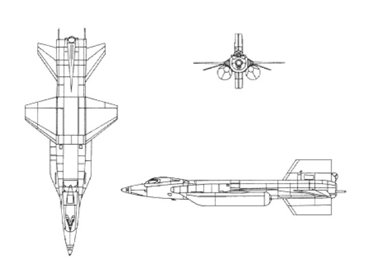
Engine: 1 x Reaction Motors XLR-99 rocket engine, 253.7kN Max take-off weight: 15422 kg / 34000 lb Wingspan: 6.7 m / 22 ft 0 in Length: 15.8 m / 51 ft 10 in Height: 4.1 m / 13 ft 5 in Wing area: 18.6 sq.m / 200.21 sq ft Max. speed: 7297 km/h / 4534 mph Ceiling: 107960 m / 354200 ft Crew: 1
First of the “Century fighters”, the prototype F-100 flew on 25 May 1953 piloted by George Welch. Powered by a Pratt & WhitneyJ57 turbojet and augmented by an after¬burner, it flew faster than sound on its maiden flight.
Originally known as the “Sabre 45”, because of its 45-degree swept wing, the F-100 is a completely new design and was the first U.S.A.F. operational aircraft to fly supersonic in level flight. In very large-scale production as standard U.S.A.F. day fighter in 1955. Established World Speed Record of 755.15 mph on 29 October 1953.
The whole F-100 structure is immensely strong and rigid; so much so that assembly jigs are rendered unnecessary, the parts being simply put together. The wing interior is largely taken up by huge forgings, machined into honeycombs or grids; some of the outer skins are machined from sheet of no less than 3in original thickness. There was talk of the aircraft being made by Commonwealth (Australia) and Canadair.
The F-100 has an all-moving tailplane and inset ailerons, each in two sections, and automatic leading-edge slats. Ailerons were located inboard and flaps were omitted. Flaps were on the F-100D and F only. An air-brake is under the centre fuselage. The tricycle undercarriage has single wheels on each main unit ad twin wheels on the nose unit. The mains retract inward into the fuselage and nose wheels retract rearward.
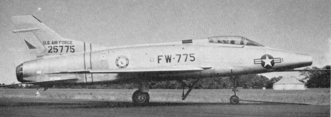
The initial production version was the F-100A, a single-seat day fighter powered by a 43.15kN J57-P-7 or P-39 engine. Armament comprised four 20mm M-39E cannon plus external stores on six under-wing hardpoints.
F-100A Super Sabre
By May 1954, the U.S.A.F. had accepted delivery of a fair number of F-100As, but some had already been damaged or written-off in accidents. The F-100A was grounded in November 1954 because of transonic control problems. The height of the rudder had been reduced by some 18in and a corresponding amount added to the fin. The F-100 lands at nearly 180 mph. There are no landing flaps, but the ventral airbrake can be used on the approach.
North American F-100A Super Sabre
The F-100A production model first flew on 29 October 1951. 203 of the F-100A and RF-100A were built, the last 35 having an 11,700 lb thrust J57-P. The RF-100A was a photo-reconnaissance conversion of the F-100A with a deeper camera-carrying front fuselage.
RF-100A 53-2600
The 1956 F-100B designation was not applied as it was extensively redesigned as the F-107.
The F-100C (NA-214, -217, -222) appeared as a single-seat fighter bomber with strengthened wings, up to 3,402kg of bombs on eight underwing hardpoints, in-flight refuelling capability and 75.62kN (with afterburning) Pratt & Whitney J57-P-21A turbojet engine. First flown on 17 Jnuary 1955, 476 were built. An F-100C set the first world speed record to exceed Mach 1 on 20 August 1955 at 822.135mph.
The TF-100C of 1956 was a planned two-place trainer version modified from F-100C 54-1960, which instead became a prototype for the F-100F. Only the one was built.
TF-100C 54-1960
The similar F-100D (NA-223, -224, -235, -245) introduced design refinements, including a taller fin, landing flaps; supersonic autopilot, low-level bombing system, and could be armed with four Sidewinder or two Bullpup missiles, or 3,402kg of external weapons in addition to its standard four 20mm cannon.
F-100D 55-2851
First flown on 24 January 1956, 1274 F-100D were built.
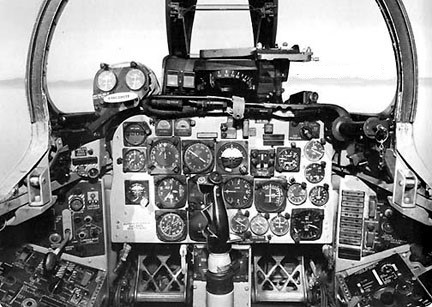
F-100D cockpit
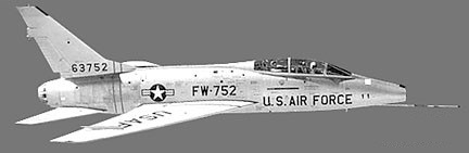
The final version built was the F-100F (NA-234, -255, -261, -262), first flown on 1 March 1957. It was a lengthened tandem two-seat operational trainer and tactical attack aircraft, armed with two 20mm cannon and capable of carrying 2,722kg of external stores. A total of 339 were built.
F-100F 56-3752
Operation Julius Caesar, involving the first flight by jet fighter aircraft over the North Pole, was conducted on 7 August 1959 with the landing of two USAF F-100F fighters at Eielson, Alaska AFB, southeast of Fairbanks, Alaska. The flight from Wethersfield, Essex, was completed in 9 hr 37 min.
Total production was 2294 aircraft when the line closed in October 1959.
After cancelling all airshows for two big summer months the Airforce Thunderbirds reverted back into F-100s in August 1965 to complete the season. They had started in Republic F-105s but a series of accidents throughout the Air Force grounded all Thunderchiefs.
F-100 Engine: 1 x P+W J-57-P-21 turbo-jet, 66.7kN Max take-off weight: 12700 kg / 27999 lb Empty weight: 9500 kg / 20944 lb Wingspan: 11.6 m / 38 ft 1 in Length: 14.3 m / 46 ft 11 in Height: 4.9 m / 16 ft 1 in Wing area: 35.8 sq.m / 385.35 sq ft Max. speed: 1216 km/h / 756 mph Ceiling: 15250 m / 50050 ft Range: 920 km / 572 miles Armament: 4 x 20mm machine-guns, 2720kg of bombs and missiles Crew: 1
North American F 100 Super Sabre Engine: Pratt & Whitney J-57-P-21A, 75645 N Length: 46.982 ft / 14.32 m Height: 14.665 ft / 4.47 m Wingspan: 38.747 ft / 11.81 m Max take off weight: 34839.0 lb / 15800.0 kg Max. speed: 751 kt / 1390 km/h Service ceiling: 45013 ft / 13720 m Range: 1304 nm / 2415 km Crew: 1 Armament: 4 mg. 3402 kg bombs
F-100A Super Sabre Engine: 10,000 lb. thrust Pratt & Whitney J57-P-7 turbojet, with afterburner. Wingspan: 36 ft. 7 in Length: 45 ft. 3 in Loaded weight: approx. 27,000 lb. Max. speed: over 760 m.p.h. Ceiling: over 50,000 ft. Range: over 1,000 miles. Armament: 4×20 mm cannon, Crew: 1.
F-100C Engine: Pratt & Whitney J57-P-21A, 16,950 lb w/afterburner Wingspan: 38 ft 9.25 in Wing area: 385.2 sq.ft Length: 54 ft 3 in Height: 16 ft 2.25 in Wheel track: 12 ft Fuel capacity: 987 Imp.Gal External fuel: 2 x 208 Imp.Gal + 2 x 187 Imp.Gal Armament: 4 x 20mm cannon Hardpoints: 6 External load: 6000 lb
F-100D Engine: Pratt & Whitney J57-P-21A afterburning turbojet, 17,000 lb / 7711 kg Wingspan: 38’10” / 11.82 m Wing area: 385.0 sq.ft / 35.77 sq.m Length: 47’2″ / 14.36 m Height: 16 ft 3 in / 4.95 m Wheel track: 12 ft Empty weight: 21,000 lb / 9525 kg MTOW: 34,832 lb / 15,800 kg Fuel capacity: 987 Imp.Gal External fuel: 2 x 208 Imp.Gal + 2 x 187 Imp.Gal Max speed: 864 mph / 1390 kph / M1.3 at 35,000 ft / 10,670 m Cruise speed: 565 mph Initial ROC: 16,000 fpm / 4877 m/min Range: 600 mi / 966 km Service ceiling: 46,000 ft / 14,020 m Armament: 4 x 20 mm cannon Hardpoints: 6 Bombload: 7500 lb / 3402 kg
F-100F Engine: Pratt & Whitney J57-P-21A, 16,950 lb w/afterburner Wingspan: 38 ft 9.25 in Wing area: 385.2 sq.ft Length: 57 ft 3 in Height: 16 ft 2.25 in Wheel track: 12 ft Fuel capacity: 987 Imp.Gal External fuel: 2 x 208 Imp.Gal + 2 x 187 Imp.Gal Armament: 2 x 20mm cannon Hardpoints: 6 External load: 7500 lb Seats: 2
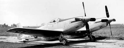
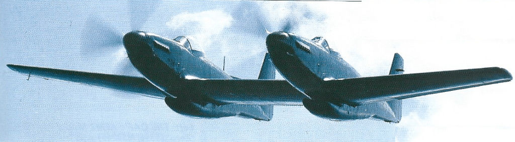
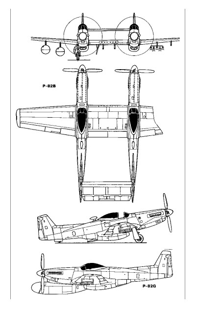
The long-range, high-altitude escort fighter, development of the P-51 Mustang, the Twin Mustang was formed by two fuselages joined by the wing and the horizontal stabilizer. The P-82 was a separate new design, not just a mating of P-51s, as commonly assumed. It was also the last prop-driven fighter to be ordered into production by USAF.
Two XP-82 (NA-120) prototypes were built (44-83886/83887) in 1945 powered by Packard-Merlin V-1650-23/25 with opposite rotating props. First flying at XP-82A on 15 April 1945.
With a pilot in each fuselage, it reduced the problem of pilot fatigue on ultra-long-range missions.
North American XP-82A 44-83888
One XP-82A (NA-120), 44-838881945, was built with Allison V-1710-119 engines.
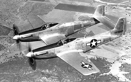
The P-82B (NA-123) of 1945 was the initial production version. Twenty were built, 44-65160-65179.
North American P-82B
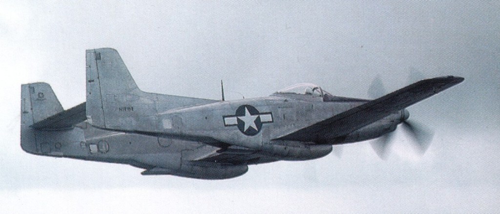
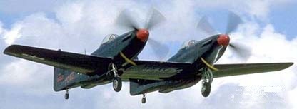
North American P-82C 44-65169
The NA-123 P-82C and -82D of 1946 were night fighter conversions of P-82Bs with a centre-section APS-4 radar pod.
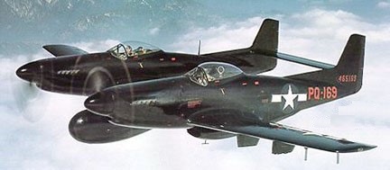
North American P-82E 46-258
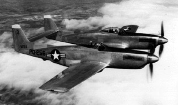
100 (46-255/354) of the P-82E / NA-144 escort fighter were built in 1946.
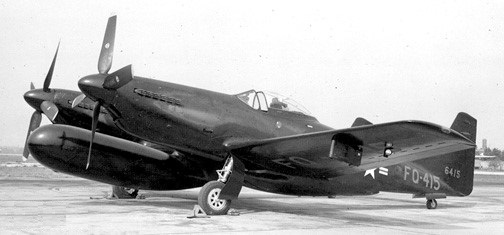
North American P-82F 46-415
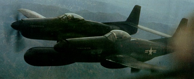
The P-82F (NA-149) and G models carried a radar operator in the right cockpit instead of a co-pilot. 100 P-82F (46-405/495) night fighter were built in 1946. 45 P-82G / NA-150 (46-355/383, -389-404) all-weather night fighter with tracking radar were built in 1946, powered by Allison V-1710-143.
An F-82G was credited with downing the first enemy aircraft in the Korean War (p: Lt William Hudson), on 27 June 1950.
F-82G
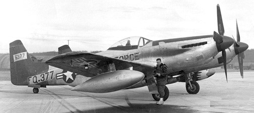
The P-82H of 1947 were Alaskan winterized conversions. Five were built from F-82F [46-384/388] and nine from F-82G [46-496/504].
North American P-82H 46-377
Re-designated F-82 in June 1948.
Although a few initial models had Merlin engines, the great majority were Allison powered and saw service in Korea.
P-82B. One of 20 initial production variants out of 500 ordered. Serialled 44-65162, restored as N12102
272 were built, the final delivery, an F-82G, in April 1949.
XP-82 / NA-120 Engines: 2 x Packard-Merlin V-1650-23/25 Props: Contra-rotating No built: 2 [44-83886/83887]
XP-82A / NA-120 1945 Engines: Allison V-1710-119 1 built 44-83888
F-82 Engine: 2 x Allison V-1710-143/145, 2300 hp Wingspan: 51 ft 3 in / 15.61 m Height: 13 ft 10 in / 4.2 m Armament: 6 x .50 mg Bombload: 2 x 4000 lb
P-82B / NA-123
P-82C / NA-123 1946 Night fighter conversions of P-82B with centre-section APS-4 radar pod. 1 built 44-65169
P-82D / NA-123 1946 Night fighter conversions of P-82B with centre-section APS-4 radar pod. 1 built 44-65170
P-82E / NA-144 1946 Escort fighter 100 built 46-255-354 Length: 39 ft 1 in / 11.88 m Height: 13 ft 10 in / 4.2 m Empty weight: 14,350 lb / 6509 kg Max loaded weight: 24,864 lb / 11,276 kg Max speed: 465 mph / 750 kph Range: 2504 mi Armament: 6 x .50 mg Bombload: 2 x 4000 lb
P-82F / NA-149 1946 Night fighter 100 built 46-405/495
P-82G / NA-150 Engine: 2 x Allison V-1710-143/145, 1600hp / 1193kW Wingspan: 15.62 m / 51 ft 3 in Length: 12.93 m / 42 ft 5 in Height: 4.22 m / 13 ft 10 in Wing area: 37.90 sq.m / 407.95 sq ft Max take-off weight: 11608 kg / 25591 lb Empty weight: 7256 kg / 15997 lb Useful load: 9594 lb Max. speed: 401 kt / 742 km/h / 461 mph Cruise speed: 285-300 mph Ceiling: 11855 m / 38900 ft Range w/max.fuel: 3605 km / 2240 miles Armament: 6 x 12.7mm machine-guns, 4x 454kg of bombs Crew: 2 45 built (46-355/383, -389-404)
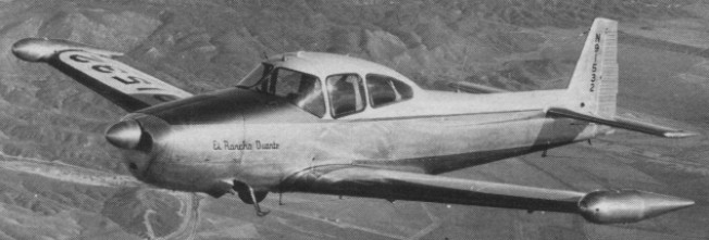
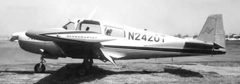
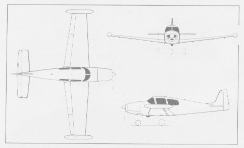
Designed by Edgar Schmued and Roy Liming, the NAvion embodied many design features of the parent P-51 Mustang, including the famed laminar-flow wing. It was priced at $7,750 which had risen to $8,990 in 1948. A large four seat all metal tourer with sliding canopy produced from 1947 to 1957.
The first 1109 were built by North American, including 47 to the USAF as L-17A (NA-154). With a market slump and increased production costs (planned selling price of $6,000 was a bit unrealistic in the face of a construction cost nearly $18,000), rights were sold in 1948 to Ryan Co, who used a lower-case “A” in the plane’s name. Ryan Aircraft who built about a thousand more.
The first 1109 were built by North American, including 47 to the USAF as L-17A (NA-154). With a market slump and increased production costs (planned selling price of $6,000 was a bit unrealistic in the face of a construction cost nearly $18,000), rights were sold in 1948 to Ryan Co, who used a lower-case “A” in the plane’s name. Ryan Aircraft who built about a thousand more.
In 1948 the original 1946 model was upgraded from 185 hp to 205 hp. The Navion B of 1951 introduced 260 hp, and the 240 and 250-hp Continentals came out in 1958 and 1959 respectively.
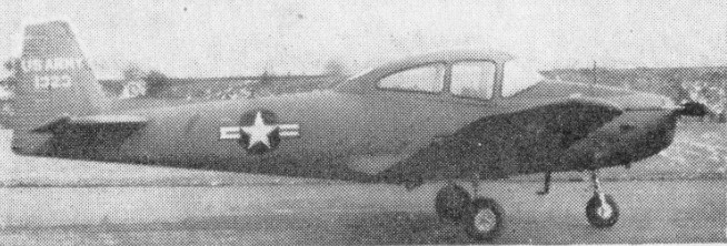
Original L-17A was military version of civil NAvion (47-1297-1379) built by North American. When Ryan took over production, 158 more were ordered by U.S.A.F. as L-17B’s. L-17C is L-17A modified by Ryan. Forty-seven L-17A went to National Guard units. All are 4-seat liaison aircraft powered by a 205 h,p. Continental O-470-3 engine. The US,A.F. transferred 170 L-17s to the Civil Air Patrol during 1954. Some were converted to QL-17 target drones.
Ryan produced more than 1000 Navion 205 during 1948-50.
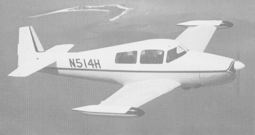
The 1960 Rangemaster G-1 was a five-seat version of North American/Ryan Navion (N514H) first flying on 10 June 1960.
Navion Rangemaster N2420T
One of the later manufacturers introduced the Rangemaster model which had conventional doors and was produced from 1962 to 1970.
Ryan L-17 Navion
Navion Aircraft Co was founded in 1965 by the American Navion Society to provide spares and support for owners of Ryan/North American Navion lightplanes. All rights to the aircraft were acquired and a developed version, the five-seat Navion Rangemaster H, was produced before the company was liquidated and taken over by the Navion Rangemaster Aircraft Company.
In 1972 Navion Rangemaster Aircraft Co purchased the assets of the bankrupt Navion Aircraft Company, including jigs, machine tools, and spare parts to support Ryan/North American Navion lightplanes. In 1973 production of the Navion Rangemaster restarted, the first aircraft flying late the following year. Consolidated Holding Incorporated acquired control of the company in 1975 and announced plans to manufacture the Rangemaster H at the rate of one per week.
Navion Rangemaster
The Navion Rangemaster has been in and out of production in the past, and its 1977 revival has at times seemed surrounded more by promises than production. Where the factory formerly sold Rangemasters direct, all selling will now be done by Two Jacks, of Olive Branch, Mississippi. Two Jacks has, in fact, obligated itself to accept 100 Navion Rangernasters, to be built during 1976-78.
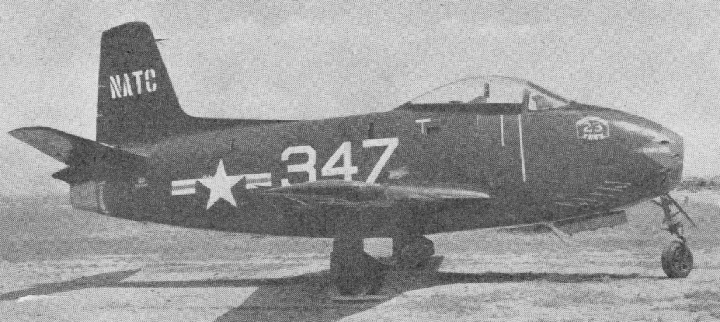
In the summer of 1944, North American Aviation completed the project design for a jet fighter using a wing based on that of the P 51 but with a completely new fuselage with a straight through jet duct from a nose inlet. Two designs were prepared, the second being a longer and heavier aircraft for the USAAF (this was later delayed and finally emerged as the XP 86, the first of the sweptwing Sabre family). The original proposal became the NA 134, ordered by the US Navy as the three XFJ-1 prototypes with the name Fury on January 1, 1945. The Navy became aware of German swept-wing data in the summer of 1945 but, unlike the USAAF, decided not to incorporate it in the new jet fighter.
A US Navy contract for the building of three XFJ-1 prototypes was awarded on 1 January 1945. Designed around the General Electric J35 axial flow turbojet, NAA chose a simple configuration with a nose intake and straight through airflow to the engine in the rear fuselage. This necessitated putting the cockpit above the intake ducting and resulted in a short and stumpy looking fuselage. The armament of six 12.7mm machine guns was installed on the sides of the nose. Fuel was housed in the fuselage and in tip tanks on production aircraft.
Like the same company’s XB 45 four jet bomber, the XFJ 1 was little more than jet propulsion applied to an advanced traditional airframe, with a laminar wing similar in profile to the P 51. The first flight was made at Inglewood on November 27, 1946, the engine being the 1733 kg (3820 lb) thrust General Electric J35 2 (TGA80) axial. By this time Inglewood was building 100 production FJ 1 Furies, with the Allison J3-A 5 2, virtually the same engine but rerated at 1814 kg (4000 lb) thrust, and with full carrier equipment and six 0.3 in (12.7 mm) guns. Features included small dive brakes above and below the non¬-folding wings, tip tanks, a primitive ejection seat and a ‘kneeling’ nose gear for stacking in a tight nose to tail line below decks. Desig¬nated NA 141, this batch was cut to 30 in 1948. Deliveries of these aircraft began in March 1948 with Allison-built engines and served only with VF 5A, soon restyled VF 51, between November 1947 and May 1949. In 1948 VF-5A (later VF-51) became the first jet unit to complete a seagoing tour of duty, aboard USS Boxer, the first carrier landing having been on March 10, 1948.
The Fury was quickly overtaken by the rapid pace of jet fighter development and remained in front line USN service for only 14 months before being relegated to Naval Reserve units. VF-5A / VF-51 was only operational squadron to fly the aircraft.
FJ-1 Fury 1948
One of the prototype FJ-1s achieved a speed of Mach 0.87 in 1947 when, the fastest by any US fighter to that point.
FJ-2
Though the original Fury was no better than several other fighters of the day, the Air Force clearly had made a major advance with the F 86 Sabre, and despite the Cutlass, Skyray and even the later McDonnell Demon the Navy decided to order a naval version of the Sabre in 1950. Confusingly, it decided to designate this FJ 2, instead of F2J, and to perpetuate the name Fury, thereby funds easier to obtain by suggesting that the type was a mere improved FJ 1 instead of a totally new aircraft. The first of the new NA 179 / XFJ-2 Fury prototypes flew on December 27, 1951 (piloted by Bob Hoover). It was essentially an F 86E with four 20 mm (0.79¬in) M 2 guns, an A frame arrester hook, catapult hooks and a lengthened nose leg, the General Electric J47 13 engine remaining.
With successful conclusion of initial carrier qualification trials aboard the USS Midway, this type was ordered into quantity production. Deliveries began in 1954, but only 200 had been completed by 1954 when production switched to the FJ-3.
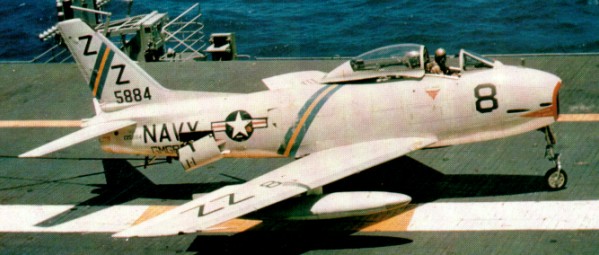
North American FJ-3 Fury
Carrier qualification was outstanding, and the Columbus, Ohio, factory (previously a Curtiss Wright facility) constructed 300 of the much refined FJ 2 production type, with 2722 kg (6000 1b) thrust J47 2 engine, modified power folding wings, wider track landing gear and APG 30 radar gunsight. Production was assigned lower priority than the F 86F, and when the Korean war ended orders were cut to 200; all were delivered in the first nine months of 1954. All served with shore based Marine fighter squadrons, with bomb racks and, from 1955, the new Sidewinder AAM.
On 3 March 1952, the design of a new Fury shipboard fighter began around the newly-available Sapphire engine, built by Wright and Buick as the J65 2 at 3538 kg (7800 1b) thrust, fed by an enlarged duct which made the fuselage deeper. Assigned the designation FJ-3, the new fighter differed from the FJ-2 primarily in having a redesigned fuselage with a deeper air intake to accommodate the Wright J65 engine, as the US-built version of the Sapphire was known. The fifth FJ-2 was adapted to take the new engine as the NA 196 XFJ-3 and flew on 3 July 1953, and the first of 389 production FJ-3 (NA 194), powered by a J65-W-4 engine rated at 7,650 lb st (3 470 kgp) and carrying an armament of four 20-mm cannon, followed on 11 December 1953. De¬liveries to the US Navy began in September 1954, and, in the following year, the wing slats were discarded in favour of extended leading edges, while, with the 345th aircraft, additional wing stores stations were introduced for 500- or 1,000-lb (227- or 454-kg) bombs or rocket packs. The navy later added 214 NA 215 models with the W 4D engine, but cut this back to an extra 149 only, for a total of 538. In August 1956, as the 538th and last FJ-3 was delivered, a new weapon capability was introduced in the form of the Sidewinder AAM. 80 aircraft subsequently being modified as EJ-3Ms which augmented cannon armament with a pair of the AAMs.
FJ-3 Fury
This fighter/bomber equipped 17 navy and four marine squadrons, and VF 21 in January 1956 became the first combat unit to embark aboard the super carrier Forrestal. (The first FJ 3 unit at sea was VF 173, aboard Bennington, in May 1955.)
From August 1956 a total of 80 FJ 3s were converted to fire Sidewinders as the FJ 3M, while later others were rebuilt as drone targets and as drone (RPY) directors. The FJ¬3D controlled the Regulus 1 ship launched cruise missile, while the FJ 3D2 was parent aircraft to F9F 6K and KDA target aircraft. By 1959 surviving FJ 3s were being rebuilt with a long chord wing, without slats, with integral wing fuel tanks and either three or four weapon pylons. In 1962 the new designations became DF 1C, DF 1D and MF 1C.
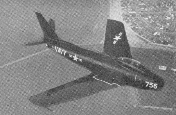
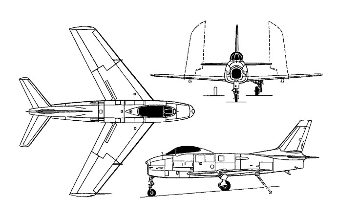
In 1953 Columbus, which from the start had a competent and aggressive design and project staff, proposed a completely re-egineered Fury with much enhanced capability. This was soon accepted, and a rebuilt FJ 3 styled NA 208 and with the Navy designation XFJ-4, flew on October 16, 1953. Hardly any part was common to earlier Furies. The wing was much broader and thinner, with mid span ailerons and full integ-ral tankage, inboard high lift flaps and small fences on a fixed leading edge. The sweep was 35 degrees. The very deep reprofiled fuselage combined with the wing to increase internal fuel capacity by M, and with the four underwing pylons all loaded the gross weight was increased by the same proportion compared with the original FJ 2. The tail was thinner, and the vertical surface taller, and much of the engineering was that of the F 100C then in production at the Ohio factory. Main gears had levered suspension and further widened track, and the result was a superior carrier based attack aircraft.
Production FJ 4 (NA 209) Furys flowed from February 1955, the engine being the 3493 kg (7700 1b) thrust J65 16A. The first batch of 150, completed in March 1957, were followed by 222 FJ 4B (71 followed by 151 improved NA 244) which finally closed out production of Sabres and Furys in the United States in May 1958. The FJ 4B had a stiffer wing with six pylons, LABS (Low Altitude Bombing System) for nuclear toss¬-delivery, extra air brakes on the rear fuselage and other changes. It was entirely configured as an attack bomber, and cleared to fire the ASM N 7 Bullpup air to surface guided missile in January 1957.
North American FJ-4B Fury
Five Bullpups could be carried, with the radio command guidance pod on the sixth pylon. In the revised Department of Defense numbering scheme the FJ 4 became the F 1E, and the FJ4B the AF 1E. The AF equipped nine navy and three marine corps attack squadrons, before being progressively transferred to the reserve in 1962 65. A little-¬known research programme involved mixed-power trials using two FJ 4 Furys with North American hydrogen peroxide rockets mounted in a fuselage extension above the normal jetpipe, and with nose extensions housing instrumentation.
Introduced to service in 1957, the FJ-4B was finally retired from the front-line inventory in late 1962 although it continued to fly with second-line squadrons and Reserve units for several more years, the post-1962 designations being F-1C (FJ-3), MF-1C (FJ-3M), F-1E (FJ-4) and AF-1E (FJ-4B). Lesser-used variants were the FJ-3D and FJ-3D2 (DF-1C and DF-1D) drone-director conversions.
FJ-1 Fury Engine: one 4.000-lb (1,814-kg) thrust Allison J35-A-2 turbojet Maximum speed 547 mph (800 km/h) at 9000 ft (2,745 m) Initial climb rate 3,300 ft (1,006 m) per minute Service ceiling 32,000 ft (9,755 m) Range w/max.fuel 1500 miles (2,414 km) Empty weight 8,843 lb (4,011 kg) Maximum take-off weight 15,600 lb (7,076 kg) Wing span 38 ft 2 in (11.63 m) without tip tanks Length 34 ft 5 in (10.49 m) Height 14 ft 10 in (4.52 m) Wing area 221.0 sq ft (20.53 sq.m) Armament: six 0.5-in (12.7-mm) machine guns Crew: 1
FJ-2 Fury Engine: GE J47
FJ-3 Fury Engine: 1 x Wright J-65-W-16A, 3470kW Max speed at sea level, 681 mph (1 096 km/h) Max speed at 35,000 ft (10 670 m) 623 mph (1 002 km/h) Initial climb, 8.450 ft/min (42,93 m/see) Range (clean), 990 mls (1 593 km) Empty weight, 12,205 lb (5536 kg) Loaded weight (clean), 17,189 1b(7 797kg) Span, 37 ft 1 ½ in(11,31 m) Length, 37ft7in(11.45m) Height, l3ft 8 in(4,16 m) Wing area, 302.3 sq ft (28,08 sq.m)
FJ-4 Engine: 1 x Wright J-65-W-16A, 3470kW Max take-off weight: 9131 kg / 20131 lb Empty weight: 5 992 kg Wingspan: 11.91 m / 39 ft 1 in Length: 11.07 m / 36 ft 4 in Height: 4.24 m / 13 ft 11 in Wing area: 31.46 sq.m / 338.63 sq ft Max. speed: 1094 km/h Range: 2390 km / 1485 miles Armament: 4 x 20mm cannon Crew: 1
FJ-4 Engine: 1 x Wright J-65-W-16A, 7700 lb Wingspan: 11.91 m / 39 ft 1 in Length: 37 ft 6 in Height: 12 ft 8 in Wing area: 31.46 sq.m / 338.63 sq ft Max take-off weight: 9131 kg / 20131 lb Empty weight: 5 992 kg Fuel capacity external: 583 Imp.Gal. Max. speed: 687 mph at SL Max ROC: 7500 fpm Range: 2390 km / 1485 miles Max range: 2700 mi Armament: 4 x 20mm cannon Crew: 1 Wheel track: 11 ft 7 in Wheelbase: 16 ft 9.5 in Underwing hard points: 6
FJ-4B/AF 1E Fury Powerplant: one 3493-kg (7,700-lb) thrust Wright J65-W-16A turbojet Maximum speed 1094 km/h (680 mph) at sea level Service ceiling 14265 m (46800 ft) Range 4458 km (2,770 miles) with maximum external fuel. Empty weight 6250 kg (13,778 lb) Maximum take-off weight 12701 kg (28,000 lb) Wing span 11.91 m(39 ft 1 in) Length 11.07 m(36 ft 4 in) Height 4.24 m (13ft 11 in) Wing area 3l.46 sq.m (338.66 sq ft) Armament: four 20-mm cannon External ordnance 2722 kg (6,000 lb)
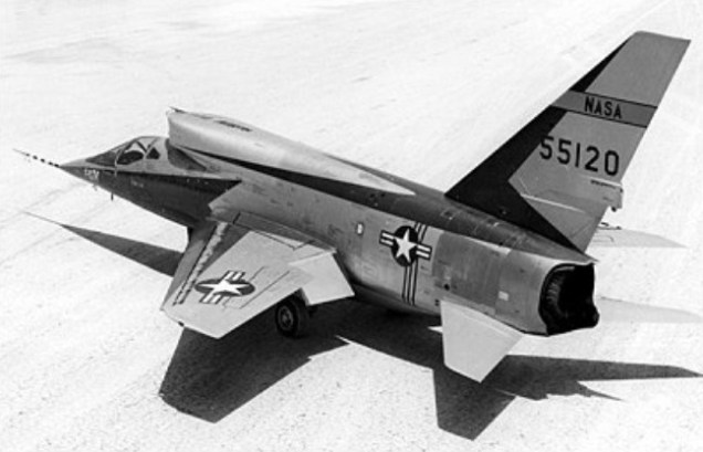
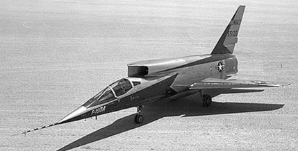
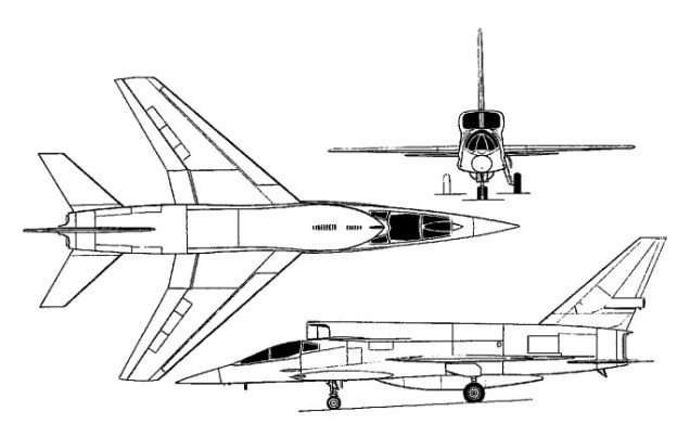
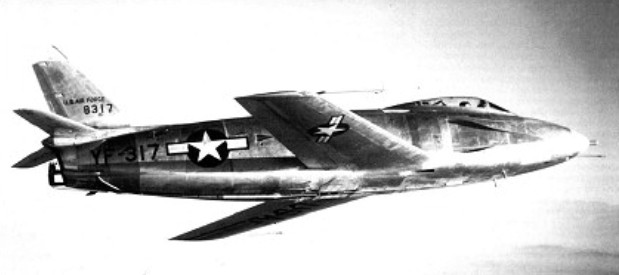
A derivative of the Super Sabre and originally designated the YF-100B, the North American F-107, or company NA-212, was an all-weather fighter-bomber version of the F-100 powered by a 10660kg thrust Pratt & Whitney YJ75-P-9 turbojet.
North American YF-107A 55-5120
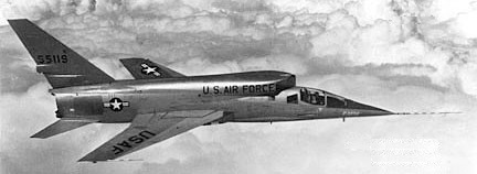
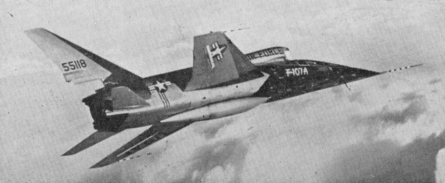
A large dorsal arrangement with bifurcated VAID (Variable Area Inlet Duct) inlets inlet was above and behind the cockpit, so positioned to create space in the nose for radar. The F-107 was equipped with a sidestick flight control system.
North American YF-107A 55-5119
Design work began in June 1953 and a year later the USAF ordered nine aircraft (55-5118 to 55-5126), although only three were actually completed (55-5118 to 55-5120). In 1955, the F-107 lost out to the Republic F-105 in a paper competition even though it had not yet flown and its competitor did not, then, have all-weather capability. Thus, the future of the F-107 was already clouded on 10 September 1956 when Robert Baker made the first flight at Edwards AFB, California, in the first of three service-test YF-107As.
The YF-107A was relatively trouble free but despite good performance, the three YF-107As were soon relegated to permanent test status. Features of the aircraft warranting further evaluation included a flush centre-line fuel tank mounted in the indented fuselage bottom, spoilers on the wing surface instead of ailerons, and a one-piece all-moving rudder, later adopted on the A-5 Vigilante attack bomber.
The first YF-107A eventually found itself in a scrap heap, the second is now on display at the Air Force Museum in Dayton, Ohio, and the third was lost in a crash landing while on loan to NACA. F-107 (Tail number 55-5118) was on display at Pima Air and Space Museum in Tucson.
YF-107A Engine: 1 x Pratt & Whitney J-75-P-9, 24,500-lb (11,115-kg) Max take-off weight: 22204 kg / 48952 lb Empty weight: 16852 kg / 37152 lb Wingspan: 11.2 m / 36 ft 9 in Length: 18.5 m / 60 ft 8 in Height: 6.0 m / 19 ft 8 in Wing area: 39.7 sq.m / 427.33 sq ft Max speed: 2200 km/h / 1367 mph Cruise speed: 700 mph Range: 1900 km / 1181 miles Ceiling: 50,000 ft Armament: 4 x 20mm cannons, 4540kg of weapons Seats: 1
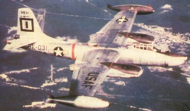
The North American F-86C developed into the YF-93A and eventually became the third design in the penetration fighter competition with the McDonnell XF-88 and Lockheed XF-90. The YF-93A was a bigger, and bulkier than the Sabre. The nose inlet of the F-86 design was replaced with side-mounted inlets and the fuselage was widened to house a 12835kg thrust Pratt & Whitney turbojet. The result was a larger, heavier machine with longer range and greater load-carrying capacity than the Sabre.
On 9 June 1948, the USAF ordered 118 F-93s, but the order was cancelled a year later. The YF-93A lost its second chance to attain production status when it emerged a poor third in the penetration fighter contest which, as it turned out, did not result in any production contract anyway.
The first of the two YF-93As, also known as the company NA-157, was first flown on 24 January 1950. The two machines underwent various modifications during evaluation, including changes in the shape of their lateral air inlets.
After the USAF was no longer a potential buyer, the two airframes were turned over to the National Advisory Committee for Aeronautics (NACA), where they were employed in various tests until eventually being retired and scrapped.
YF-93A Engine: 12835kg thrust Pratt & Whitney turbojet Max take-off weight: 12025 kg / 26511 lb Empty weight: 16360 kg / 36068 lb Wingspan: 11.81 m / 38 ft 9 in Length: 13.44 m / 44 ft 1 in Height: 4.78 m / 15 ft 8 in Wing area: 28.43 sq.m / 306.02 sq ft Max. speed: 1140 km/h / 708 mph Ceiling: 14265 m / 46800 ft
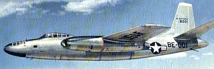
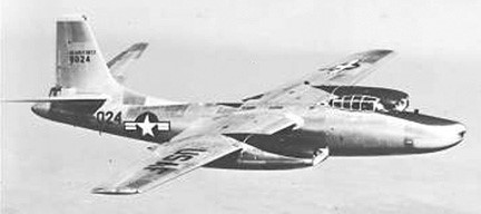
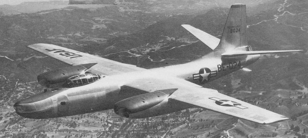
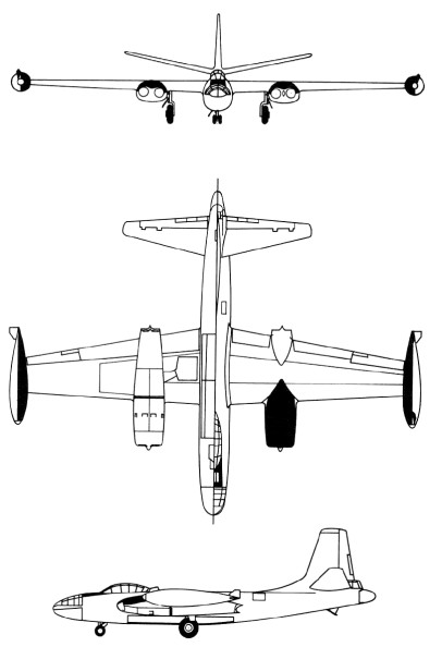
In 1943, aware of Nazi Germany’s advances in the field of jet propulsion, the Army Air Forces (AAF) asked the General Electric Company to devise a more powerful engine than its prospective axial turboprop. This eventually brought about the production of the J35 and J47 turbojets. In 1944, 1 year after the jet engine requirements were established, the War Department requested the aircraft industry to submit proposals for various jet bombers, with gross weights ranging from 80,000 to more than 200,000 pounds, and only 4 contractors answered the call. The design was frozen in early 1945.
Pressed for time, the AAF in 1946 decided to skip the usual contractor competition, review the designs, and choose among the proposed aircraft that could be obtained first. The multi-jet engine B-45, with the understanding that if a less readily available bomber was to prove superior enough to supplant it (which the Boeing XB-47 did), that aircraft would also be purchased.
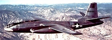
The design was generally conventional, though the main gears had very large single wheels which retracted sideways into the wing roots. In normal bomber versions the bomb aimer/navigator occupied the capacious pressurized nose, the two pilots sitting in a tandem fighter like cockpit farther aft and above, with a large multi pane canopy. The crew door was on the left side of the forward fuselage. A gunner was housed in a pressurized tail compartment.
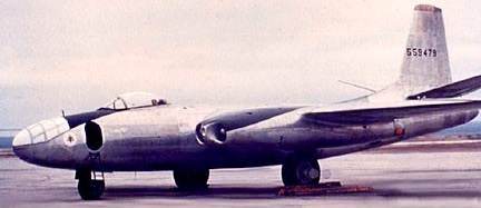
The first flight was on 17 March 1947 (piloted by George Krebs) and testing of the XB-45 prompted pre-production changes. North American Aviation redesigned the nose panel, increased the aircraft’s stabilizer area, and lengthened the tailplane by nearly 7 feet.
North American XB-45 45-59479
North American XB-45 45-59480
In August 1948, 22 of the 90 B-45s, ordered less than 2 years before, reached the newly independent Air Force. However, the B-45’s weight and takeoff distances had increased, and numerous structural and mechanical defects appeared.
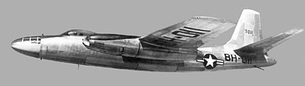
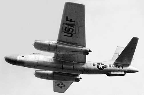
In November 1948 the B 45A (NA-147) went into service with the 47th Bombardment Group of the USAF, later based in England. Ninety-six were built (47-001/097, the last one of which was a static test-frame.
North American B-45A 47-011
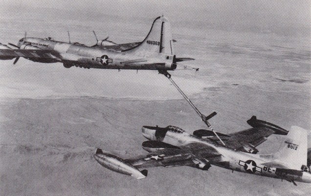
In June 1951 an RB-45 became the first jet bomber to be refuelled in flight by a Boeing KB-29.
Boeing KB-29 and North American RB-45 Tornado
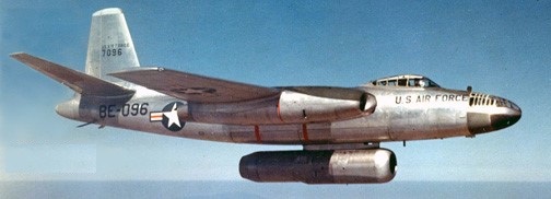
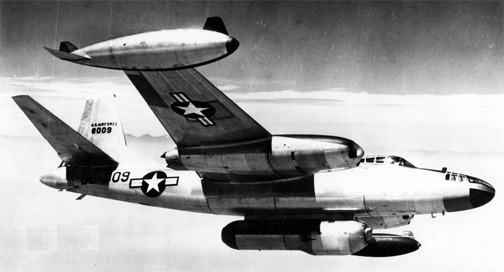
The DB-45A were conversion of B-45A as guided missile director. The JB-45A 47-096 and JB-45C of 1950 were engine test beds for Westinghouse and General Electric.
North American JB-45A 47-096
North American JB-45C 48-009
The fourteen TB-45A were target tugs modified from B-45A.
The B-45B was a project only, none were built.
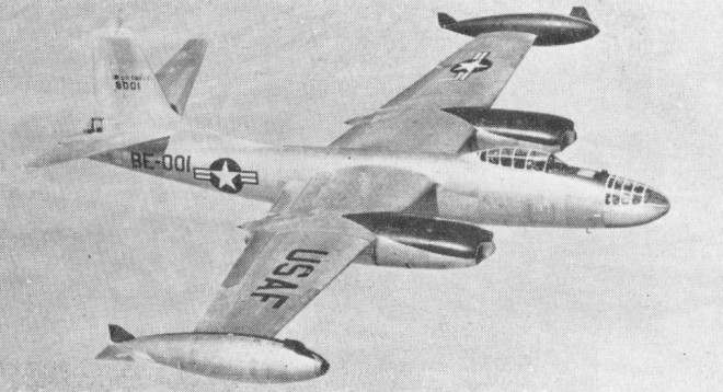
Ten B-45C (NA-153 48-001/010) were built in 1950. The DB-45C were conversions of B-45A as guided missile director.
North American B-45C 48-001
Thirty-three RB-45C and JRB-45C (NA-153 48-011/043) were built in 1949 for Photo-recon.
North American RB-45C 48-024
North American JRB-45C 48-017
As the B-47’s future production had become certain, in mid-1948 the Air Staff questioned the B-45’s value as well as its potential use. As President Truman slashed Air Force expenditures, the programmed production of B-45s was reduced to a total of 142 aircraft at a unit cost of US$1,081,000.
Only 96 B 45As were built, plus 10 of the stronger and more powerful B 45C which was disting¬uished by large wingtip tanks. Many A models were modified to B 45C standard. The final 33 aircraft were RB-¬45C camera aircraft, some of which (unlike the bomber versions) operated over Korea. Some had water injection tanks hung under the twin engine nacelles, jettisoned after take off.
Although continuously plagued by engine problems, component malfunctions, lack of spare parts, and numerous minor flaws, the B-45 regained importance. The B-45 was designed to carry both conventional and atomic bombs. Under the code name of Backbreaker, several distinct atomic bomb types and large amounts of new electronics support equipment had to be fitted in place of the standard components. In addition, the 40 B-45s allocated to the Backbreaker program also had to be equipped with a new defensive system and extra fuel tanks. Despite the magnitude of the modification project, plus recurring engine problems, atomic-capable B-45s began reaching the United Kingdom in May 1952, and deployment of the 40 aircraft was completed in mid-June, barely 30 days behind the Air Staff deadline.
B-45C Tornado
The British and American military intelligence services collaborated under utmost secrecy. Thus in 1952 four American RB-45C reconnaissance aircraft, wearing British colours but without registration marks, operated from RAF Sculthorpe on photo-missions over East Germany and other Eastern-bloc countries. Very up-to-date for the time, the RB-45C was equipped with 12 cameras. The aircraft were based at Sculthorpe in January 1952 as a detachment of the 91st Strategic Reconnaissance Wing of SAC.
The last B 45s were withdrawn from combat duty in mid-1958. The entire contingent, Backbreaker and reconnaissance models included, was phased out by 1959. Yet, the B-45 was the Air Force’s first jet bomber and as the first atomic carrier of the tactical forces.
XB-45 / NA-130 Engines: 4 x GE TG180, 4000 lb Speed: 536 mph
B-45A Tornado Engines: 4 x GE J47, 5200 lb Wingspan: 89’1″ Length: 75’4″ Max speed: 575 mph Cruise speed: 455 mp Crew: 3-4
B 45C Tornado / NA-153 Engines: four 2359 kg (5,200 lb) thrust General Electric J47 GE 13/15 turbojets (some with water injection 2722 kg/6,000 lb) Wing span over tip tanks: 29.26 m (96 ft 0 in) Length: 22.96 m (75 ft 4 in) Height 7.68 m (25 ft 2 in) Wing area: 109.2 sq.m (1,175.0 sq ft) Empty weight 22182 kg (48,903 lb) MTOW: 51235 kg (112,952 lb) Max speed 932 km/h (579 mph) at low level Service ceiling: 13165 m (43,200 ft) Range 3074 km (1,910 miles) Armament: two 12.7 mm (0.5 in) machine guns in tail turret Internal bombload of up to 9979 kg (22000 lb). Crew: 3
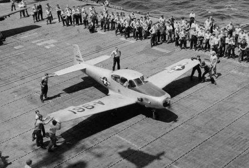
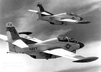
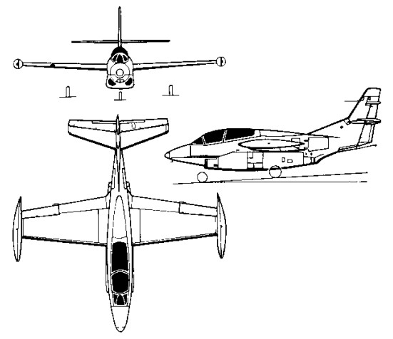
With a requirement in 1956 for a multi-role jet trainer, the US Navy awarded North American a contract to build its North American NA-241 design, which combined proven components and equipment from earlier aircraft manufactured by the company. Ordered as the T2J-1 (later T-2A), this trainer combined a wing derived from the FJ-1 Fury and the control system of the T-28C Trojan with a single 1542kg thrust Westinghouse J34-WE-36 turbojet, and accommodated the instructor and pupil in tandem, seated (eventually) on zero-zero ejection seats.
The first of six initial production T-2As was flown on 31 January 1958 and deliveries to the US Navy began in July 1959, by which time the name Buckeye had been allocated to this trainer. Equipping US Navy Training Squadrons VT-4, -7, -9 and -19, a total of 217 T-2As was built.
Two T-2A were modified to serve as YT-2B prototypes, in which the single J34 turbojet was replaced by two 1361kg thrust Pratt & Whitney J60-P-6 turbojets. The first was flown on 30 August 1962, being followed by 97 similar T-2B aircraft , 152382-152391, 152440-152475, 153538-153555, and 155206-155238 (NA-280, -288, -291, -294, -310) from 1962.
Rockwell-North American T-2B
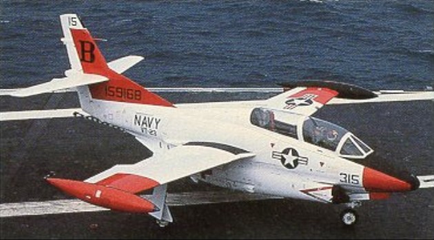
Final production version was the 1958 T-2C (NA-307, -318, -332, -340) which introduced General Electric J85 turbojets, preceded by a single YT-2C prototype conversion from a T-2B.
A total of 273 was built under US Navy contracts before production ceased, comprising 231 T-2Cs for navy use (155239-155241, 156686-156733, 157030-157065, 158310-158333, 158575-158610, 158876-158911, 159150-159173, 159704-159727) plus 12 T-2D and 30 T-2E aircraft in 1969, procured for Venezuela and Greece respectively.
The DT-2C was a drone director conversion.
It was to be re¬tired in favour of the more advanced T 45 Goshawk which has cockpit instrumentation similar to the F/A-18 Hornet.
T 2A Engine: 1 x 3,400 lbs.t. (1542 kpg) Westinghouse J34 WE 36 Max speed, 492 mph (792 kph) at 25,000 ft (7620 m) Cruise, 422 mph (679 kph) Initial climb, 5,000 fpm (25.4 m/sec) Service ceiling, 42,500 ft (12 950 m) Range, 550 mls (885 km) Empty weight, 6,893 lb (3 127 kg) Loaded weight, 9,916 lb (4498 kg) Span, 36 ft (10.97 m) Length, 38 ft 8 in (11.78 m) Wing area, 255 sq.ft (23.7 sq.m)
T 2B Engines: 2 x 3,000 lbs.t. (1316 kgp) J60. MTOW: 12,300 lb Top speed: 545 mph
YT-2B / T 2B Engines: 2 x J60-P, 3,000 lbs.t. (1316 kgp) Useful load: 3842 lb Speed: 540 mph Ceiling: 44,000 ft
T-2C / DT-2C Engines: 2 x General Electric J85-GE-4 turbo-jet, 13.1kN / 2950 lb Max take-off weight: 5978 kg / 13179 lb Empty weight: 3681 kg / 8115 lb Wingspan: 11.63 m / 38 ft 2 in Length: 11.79 m / 38 ft 8 in Height: 4.51 m / 14 ft 10 in Wing area: 23.70 sq.m / 255.10 sq ft Useful load: 5065 lb Max speed: 521 mph Cruise speed: 465 mph Ceiling: 13535 m / 44400 ft Range: 1465 km / 910 miles Crew: 2
T-2J Engines: 2 x Westinghouse J34, 3400 lb Wingspan: 36’0″ Length: 38’4″ Max speed: 494 mph Cruise speed: 417 mph Stall: 67 mph Range: 967 mi