Osbourn Twin Cadet

This powered converison of a T8 Tutor was made by E. W. Osbourn at Cranfield, Bedfordshire, in 1969 and was known as the Twin Cadet Mk 1. It was fitted with two 197cc Villiers 9E single-cylinder two-stroke engines mounted on the wing bracing struts and driving two small propellers just behind the pilot’s head. The prototype, G-AXMB (ex-VM590 and BGA 805) first flew with power on 20 September 1969. and received its Authorisation to Fly on 2 July 1970. It was later re-engined with a single 500cc Triumph T100 motorcycle engine mounted in the nose and first flew in this form as the Cadet Mk 2 at Cranfield on 22 January 1972, receiving its Authorisation to Fly on 6 June that year.

Twin Cadet Mk 1
Span: 38 ft 6 in
Length: 20 ft 10.5 in
Tare weight: 455 lb
All-up weight: 657 lb
Max speed: 60 mph (power on)
Cruising speed: 40 mph (power on)
Range: 100 miles

Orlican VT-16 Orlik / VT-116 Orlik II / Let VT-16 Orlik

The VT-16 Orlik was designed by Jiri Matejček and is a high-wing monoplane of all-wood construction, except that the skin is stabilized with Umakol high-smoothness polystyrene foam. Its wing has a single spar structure with a forward torsion box; the whole wing is plywood skinned and foam filled, allowing the ribs to be comparatively widely spaced. In plan it is straight-tapered with blunt tips; there are 3° of dihedral. It has conventional plain ailerons and spoilers at mid-chord, which extend both above and below the wing.

The pilot sits under a detachable one-piece canopy, with oxygen and radio equipment as optional. The landing gear consists of a non-retractable monowheel and a tailskid. The wooden fin and rudder are both fabric-covered and the all-moving tailplane has a leading edge structurally similar to the wing, with fabric covering aft of the spar, and an anti-servo tab fitted.

The VT-16 Orlik prototype was built by some of the design staff of the Czech Republic Orlican National Works.
At the time of its first flight in August 1959 it was a Standard Class glider with a 15 m (49 ft 3 in) span. Later aircraft had 16 m (52 ft 6 in) and 18 m (59 ft 1 in) spans but it was the 16 m version that went into series production at the Orlican National Works at Chocen.

Orlik I on display at the Prague Aviation Museum, Kbely

25 VT-16 Orliks were produced in the first series production run, going to Czech gliding clubs. The Orlik also set several new Czech national gliding records during 1962.

15 VT-16s and 48 VT-116s remain on the Czech civil aircraft register in 2010, though some are disassembled.

VT-16
Span: 52 ft 6 in / 16 m
Length: 24 ft 3 in / 7.40 m
Height: 4 ft 7 in
Wing area: 137.8 sq.ft / 12.80 m2
Aspect ratio: 20.0
Airfoil: NACA 64-818
Empty weight: 474 lb / 215 kg
Max weight: 705 lb / 320 kg
Wing loading: 25.0 kg/m2 (5.1 lb/sq ft)
Max speed: 140 mph / 220 km/h / 120 kn (in smooth air)
Stall speed: 61 km/h / 38 mph / 33 kn
Min sinking speed: 0.56 m/s / 110 ft/min at 63 km/h / 39 mph / 34 kn
Best glide ratio: 32.6:1 at 44 mph / 71 km/h / 38 kn
Seats: 1
about 85 built

VT-116 Orlik II
about 220 built.

Orlican VSO 10

This Czech high performance single-seater was created by the Vyvojova Skupina Orlican – VSO group, whose chief designer is Dipl-lng Jan Janovec and which was formed by members of the former VSB (the Aircraft Faculty of Brno Military Academy) and some of the design staff of the Orlican National Works, which had built the VT-16 Orlik; VSB had produced the VSB-66-S Orlice V-tailed single-seat Standard Class design which first flew on 17 September 1970.

The VSO 10 is the VSO group’s first design and is of mixed construction, employing wood, glassfibre and metal. Design work began in March 1972 and construction of three prototypes, one a static test airframe, began in 1975.

The cantilever single-spar shoulder wings have slight forward sweep and are all-wood structures with a sandwich skin; the slotted ailerons are also of wood and there are metal DFS air brakes in the upper surfaces. The front and centre fuselage sections are glassfibre monocoque structures, the centre portion being reinforced by a steel tube frame on which the wings are mounted. The rear fuselage is a monocoque made of aluminium alloy sheet. The metal T-tail has a fixed-incidence tailplane and fabric-covered rudder and elevators. There is a retractable rubber-sprung monowheel with a drum brake, and a semi-recessed unsprung tailwheel. The pilot sits under a detachable canopy.

The first flight took place on 26 October 1976 and series production began in December 1978.

The VSO-10G took first and second places at the first International Club Class competition held in Sweden in the summer of 1979. To comply with Club Class rules the retractable monowheel was locked down and covered with a glassfibre fairing, this variant being known as the VSO-10C.

VSO 10
Span: 15.0 m / 49 ft 2.5 in
Length: 7.0 m / 22 ft 11.75 in
Height: 1.20 m / 3 ft 11.25 in
Wing area: 12.0 sq.m / 129.2 sq.ft
Aspect ratio: 18.75
Wing section: Wortmann FX-61-163/FX-60-126
Empty weight: 234.4 kg / 516.75 lb
Max weight: 380 kg / 837 lb
Water ballast: None
Max wing loading: 31.67 kg/sq.m / 6.49 lb/sq ft
Max speed: 161 mph / 140 kt / 260 km/h (in smooth air)
Max aero-tow / rough air speed: 99 mph / 88 kt / 163 km/h
Stalling speed: 37 kt / 68 km/h
Min sinking speed: 2.07 ft/sec / 0.63 m/sec at 45 mph / 39 kt / 72 km/h
Best glide ratio: 36.2:1 at 58.5 mph / 51 kt / 94 km/h

Orenda PS.13 Iroquois / Avro Canada Iroquois

The Orenda PS.13 Iroquois was an advanced turbojet engine designed for military use. It was developed by the Canadian aircraft engine manufacturer Orenda Engines, a part of the Avro Canada group. Intended for the CF-105 Arrow interceptor, development was cancelled, along with the Arrow, in 1959.

For the CF-105 Arrow project, Avro Canada had originally intended to use one of three different engines, all UK designs: Rolls-Royce RB.106, the Bristol B.0L.4 Olympus, or a license-built version of the Olympus, the Curtiss-Wright J67. The RB.106 and J67 were selected as the primary and backup engines for the new design. However, both the RB.106 and J67 were cancelled during the Arrow’s design phase, too far into the program to select the Olympus. Orenda Engines quickly responded with the PS.13 Iroquois design.

The Iroquois design was based on simplicity and lightness. With this in mind, Orenda pioneered work in the use of titanium in engines, with 20% by weight of the Iroquois (mainly the compressor rotor blades) consisting of this metal. Titanium has light weight, high strength and good temperature and corrosion resistance. It was estimated that the engine would be 850 pounds (386 kg) lighter than if steel had been used. During the early 1950s, this material was in short supply, and the lack of knowledge of its physical properties and fabrication techniques created problems which had to be overcome. It was also very expensive relative to the more common materials such as steel and aluminum.

It was recognized that if the engine parts could be designed with titanium, then the supporting structure could also be lightened due to reduced forces within the engine, with an overall saving in weight. Other parts, such as gearbox casings were made with a magnesium alloy. Inconel was used to make the blades in the low pressure turbine assembly and the metal insulation blanket found at the rear of the engine. This heat resistant nickel-chrome alloy retains its strength at high temperatures and resists oxidation and corrosion. The primary reason for using these advanced metals was to save weight and improve performance, creating an engine with a 5:1 thrust to weight ratio that could produce a sea level dry thrust of 19,250 lb (26,000 lb with afterburner). The design, development and manufacture of such an advanced jet engine was accomplished in an incredibly short time by the Orenda team. The detailed design was completed in May 1954, and the first run was achieved on 15 December 1954. The earlier Orenda 9 had more parts but produced less power. For example, the Orenda 9 weighed 2,560 lb (1,160 kg) and produced 6,355 lb (2,883 kg) static thrust, while the Iroquois weighed 5,900 lb. (2,675 kg) but was reported to have produced 30,000 lb (13,608 kg) static thrust with afterburner for takeoff. (The Orenda did not have an afterburner.)

The Iroquois was one of the most powerful jet engines in the world at its time of introduction, rated at 19,250 lbf (85.6 kN) dry, 25,000 lbf (111 kN) afterburning. It was aerodynamically matched for peak performance at 50,000 feet (15,200 m) altitude and Mach 2 speed.

Wind tunnel tests demonstrated the engine’s successful operation under sustained high inlet temperatures, and the ability to make normal relights up to 60,000 ft (18,290 m), the limit of the wind tunnel in which the tests were conducted. By 1958, the Iroquois had completed more than 5,000 hours of ground running, and many thousands of hours had also been spent testing the engines’ principal components, at the Orenda testing facilities at Nobel, near Parry Sound, Ontario.

In 1956, a U.S. Boeing B-47 Stratojet was loaned to the Royal Canadian Air Force to flight test the Iroquois for use in the CF-105. Canadair, the sub-contractor, attached an Iroquois to the right side of the bomber’s rear fuselage, near the tail, simply because there was no other place to mount it. Designated CL-52 by Canadair, it was a nightmare to fly, since the thrust was asymmetrical; this created great problems for flight control. After the Arrow project was cancelled, the B-47B/CL-52, which had logged about 35 hours of engine flight tests, was returned to the U.S and subsequently scrapped. The CL-52 was the only B-47 used by any foreign service.

After some 7,000 hours of development testing, including tests up to a simulated altitude of 70,000 feet (21,300 m) and a forward speed of Mach 2.3, the program was cancelled, along with the Arrow, on 20 February 1959.

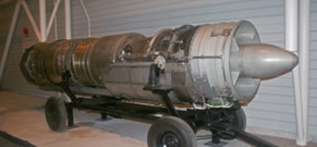
The Canada Aviation and Space Museum in Ottawa houses the nose and cockpit section of Arrow RL 206, along with various wing and fuselage components, and a complete Iroquois-2 engine, Serial Number 117. An example of an Iroquois-1 engine is found at the Canadian Warplane Heritage Museum in Mount Hope, near Hamilton, Ontario. Another Iroquois-2 engine is owned by a private collector in Fort St. John, British Columbia. Since 2011, an Iroquois engine, serial X-116, has been being rebuilt by S & S Turbines in Canada.

Iroquois 2
Type: Twin-spool turbojet
Length: 231 in (590 cm)
Diameter: 42 in (110 cm)
Dry weight: 4,650 lb (2,110 kg)
Compressor: 10-stage split axial flow compressor
Combustors: Annular combustion chamber
Turbine: Single-stage HP, two-stage LP, axial flow
Maximum thrust: 20,000 lbf (89 kN), without afterburning; 30,000 lbf (130 kN), with afterburning
Overall pressure ratio: 8:1
Specific fuel consumption: 0.85 (non-reheat), 1.9 (with reheat)
Thrust-to-weight ratio: 6.45:1 at maximum thrust

Operation Sigma Sigma 1

Operation Sigma was set up in 1966 with the object of building a pre-eminent sailplane for the British entry at the 1970 World Championships at Marfa, Texas. Rear Admiral Nick Goodhart was appointed project manager and manufacture of this very high performance sailplane was financially assisted by companies both within and outside the aviation industry.

The idea was that Sigma should have two sets of wings: one for thermalling at low speeds with low minimum sink, and the other for good performance at high speeds for cross-country flying. The two wing sections were specially developed for the project by Dr F.X. Wortmann.

Sigma’s wing consists of a light alloy box structure with full span flaps. These hydraulically operated flaps move in a similar manner to Fowler flaps but the gap between wing and flap is sealed with a flexible closure plate on the lower surface of the wing and spoilers on the upper surface to form a continuous extension of the wing. Each flap carries a full-span trailing edge aileron on the outer panel, and a camber-changing flap on the inner panel. These surfaces remain exposed when the flap is retracted. With the flap extended the circling speed and low sink rate should give a better rate of climb in weak thermals. Forward of the aileron on the upper surface is a light alloy spoiler to assist with lateral control at low speeds. With the flaps retracted the high wing loading and low drag should give a high lift/drag ratio at high speeds. The braking system is operated by lowering the camber-changing flaps and raising the spoilers on the upper surfaces to control the speed.

The fuselage is of the pod and boom type with welded steel tube centre structure faired by the wood framed glassfibre cockpit pod and with the tailboom of light alloy monocoque bolted to it. The long undercarriage is used to ensure that the wing tips have satisfactory ground clearance, necessary due to the large span and the degree of wing flexibility. The retractable sprung tail wheel is mounted in the rudder base and is operated by cables from the main undercarriage. The rudder incorporates a brake parachute. The tail unit is of light alloy construction with an all-moving T-tailplane incorporating a full-span anti-balance trim tab. The flying controls are all manually operated except for the flaps and the undercarriage, which are hydraulically operated. The hydraulic pressure is achieved by the pilot pushing both rudder pedals back and forth to operate the hydraulic pump.

The aircraft flew for the first time on 12 September 1971 with Nick Goodhart at the controls. Many aspects of handling and performance had been developed to a satisfactory level, but it did not prove possible to overcome difficulties associated with the flaps and flexible closure plates.

In 1977 the project was taken over by Prof. David J. Marsden of the University of Alberta, who designed and built the Gemini two-seater sailplane. He proposes to replace Sigma’s present flaps by simple slotted flaps in the course of his research on variable geometry sailplanes.

Sigma 1
Wing span: 21.0 m (68 ft 10 in)
Length: 8.81 m (28 ft 10 in)
Height: 1.83 m (6 ft 0 in)
Wing area: 12.2 sq.m (131.3 sq ft)
Wing section: Wortmann FX-67 Series
Aspect ratio: 36.2
Empty weight: 607 kg (1,338 lb)
Max weight: 703 kg (1,550 lb)
Water ballast: None
Max wing loading: 57.6 kg/sq.m (11.79 lb/sq ft)
Max speed: 140 kt (259 km/h)
Stalling speed: 37.5 kt (69.5 km/h)
Max rough air speed: 110 kt (204 km/h)
Best glide ratio: 48 at 63 kt (117 km/h)

Operation Sigma

Operation Sigma Ltd was formed, in February 1966, by leading members of the British gliding movement to produce a British designed and built open-class World Championship sailplane. The target was to win the World Championship’s in 1969, and the directors were G.E. Burton, M.I. Gee, H.C.N. Goodhart, F.G. Irving, B.S. Shenstone, W.N. Slater, C.O. Vernon, L. Welch, and K.G. Wilkinson.

For the first nine months there were no staff on the company payroll and the work was all done by members of the Board. This involved research and the raising of the necessary capitol. The decision by the International Competition Committee to hold World Championships in 1968 and 1970 instead of 1969 caused the Sigma board to set the target at the 1970 Championships.

In November 1966 N. Beckett was appointed aerodynamicist to the project and this was followed, in January 1967, by the appointment of J.L. Sellars, the designer of the Slingsby T.53, as Chief Designer. Her was based at Kirkbymoorside where Slingsby Sailplanes Ltd provided office and workshop space following thei appointment as sub-contractors for the construction of the Sigma prototype. Slingby’s provided design and works staff under contract to Sigma, and construction of the Sigma A and B prototype sailplanes commenced at Kirkbymoorside in the spring of 1968.

Work proceeded to schedule until November 18 when Sigma lost everything in the fire at Slingsby’s. The partly constructed wings and fuselage of Sigma A were completely destroyed and the Design Office was gutted. The Sigma Board decided to continue the project, and wok started to re-draw the lost drawings although many areas of the structure were re-designed to simplify manufacture, particularly the wings, in the light of experience already gained.

Construction of the jigs for the Sigma C commenced in Slingsby’s joinery works and detail parts were made again although it was realised that the 1970 Championships target was not likely to be achieved. It was suggested that construction of the wings should be sub-contracted but this was decided against due to cost. As a result, J.L. Sellars resigned from the project in July 1969. The bankruptcy of Slingsby’s later in the same month then caused a complete cessation of work on the prototype, apart from one person acting as liaison with sub-contractors and looking after the project’s assets.

The Sigma Board decided that the project should continue, and alternative premises were sought. British European Airways then offered space in some empty workshops in London Airport, and these were accepted. The one remaining member of the staff crated up all the jigs, drawings and parts, and sent them in two trucks to Heathrow where Lorne Welch took over the whole project, as full-time Project Director, in September 1969. Construction started again with facilities and staff sub-contracted from B.E.A.

On Mark Marketeer / Marksman

Formed 1954 as a specialist maintenance and modification contractor for Douglas B-26 Invader bombers, developing high-speed executive transport and heavily armed counterinsurgency versions. The On Mark Marketeer was a six/eight-seat corporate transport based on the B-26 airframe. The externally similar Marksman had a pressurized cabin. A B-26K Counter Invader was developed for the USAF’s Tactical Air Command.

The On Mark Com¬pany took in the surplus bombers at Van Nuys, California and turned them out with everything intact but the bomb bay doors and some of the military weapons control gear. They came to the customers in pressurized and unpressurized versions, and they were only for the select few. 45-60 were converted.

The Counter-Invader was a cleaned up, heavily armed version for the USAF’s Special Air Warfare Center.

On Mark Engineering Co

Formed 1954 as a specialist maintenance and modification contractor for Douglas B-26 Invader bombers, developing high-speed executive transport and heavily armed counterinsurgency versions. The On Mark Marketeer was a six/eight-seat corporate transport based on the B-26 airframe. The externally similar Marksman had a pressurized cabin. A B-26K Counter Invader was developed for the USAF’s Tactical Air Command.

In 1962 Mark was responsible for the first Pregnant Guppy conversions of the Boeing Stratocruiser, on behalf of Aero Spacelines Inc, for the transportation of space rockets and other bulky cargo.

At about the time Grumman was casting the Gulfstream in stone, there was a meeting at On Mark to decide upon a new airplane, a turboprop of original design. Although its ultimate price would have been equal to or less than the Gulfstream’s first tag of roughly $800,000, the directors of On Mark decided that nobody would pay such a price for a business airplane. And the company died.

Onishi OS-G3

Designed and built by Mr Onishi, a Japanese sailplane pilot, the OS-G3 single-seater is powered by six model aircraft engines, mounted three on each side of the nose on a strut braced boom in line with the front of the cockpit canopy; these engines are intended to overcome the need for winch-launching or aero tows. Each 10cc OS.60 two-stroke glowplug engine drives a 12in diameter two-bladed propeller and develops 1.7hp at 14,000rpm, or 1.275hp at a less noisy 8,000rpm, the six together producing a total of 10.2hp for take-off, or 7.65hp for cruising flight. This is just enough for an unaided take-off, the take-off run being about 500ft when the OS-G3 made its first flight early in 1977. This power output leaves a 3mph margin between the cruising speed of 24mph and the stalling speed. The payload was only 154lb.

The OS-G3 is a cantilever shoulder-wing design with a swept back fin and rudder and the tailplane mounted on top; the engine slipstream is in line with the wing leading edge. There are no flaps or air brakes, and the landing gear consists of a fixed monowheel, a fixed nosewheel and a tailskid. The pilot sits under a one-piece canopy, and has six throttle levers and six cut-out switches for the engines.

Span: 46 ft 3 in
Length: 21 ft 3.5 in
Height: 5 ft 2.5 in
Wing area: 185 sqft
Aspect ratio: 11.6
Empty weight: 143 lb
Max gross weight: 297 1b
Cruising speed: 24 mph
Stalling speed: 21 mph