The Rocketdyne AR-2 is fitted above and aft of the J79 engine in the Lockheed NF-104A. To attain a 25 mile altitude the 6000 lb thrust engine burns a mixture of JP-4 jet fuel and hydrogen peroxide.
The AR-2 is throttleable from 50 to 100% power. The NF-104A provides spaceflight experience at a fraction of X-15 operating costs.
The RS-25, otherwise known as the Space Shuttle Main Engine (SSME), is a liquid-fuel cryogenic rocket engine that was used on NASA’s Space Shuttle. Built in the United States by Rocketdyne, the RS-25 burns cryogenic liquid hydrogen & liquid oxygen propellants, with each engine producing 1,859 kN (418,000 lbf) of thrust at liftoff. Although the RS-25 can trace its heritage back to the 1960s, concerted development of the engine began in the 1970s, with the first flight, STS-1, occurring on April 12, 1981. The RS-25 has undergone several upgrades over its operational history to improve the engine’s reliability, safety and maintenance load.
The engine produces a specific impulse (Isp) of 453 seconds (4.44 km/s) in a vacuum, or 363 seconds (3.56 km/s) at sea level, consumes 1,340 L (350 US gal) of propellant per second, has a mass of approximately 3.5 tonnes (7,700 pounds) and is capable of throttling between 67% and 111% of its rated power level in one-percent increments. The RS-25 operates at extreme temperatures, with the liquid hydrogen fuel being stored at −250 °C (−418 °F) while the temperature in the combustion chamber reaches 3,315 °C (6,000 °F), higher than the boiling point of iron.
On the Space Shuttle, the RS-25 was used in clusters of three engines mounted in the aft structure of the Orbiter, with fuel being drawn from the external tank. The engines were used for propulsion during the entirety of the spacecraft’s ascent, with additional thrust being provided by two solid rocket boosters and the orbiter’s two AJ-10-190 Orbital Maneuvering System engines. Following each flight, the engines were removed from the orbiter, inspected and refurbished before being reused on another mission.
The RS-25 engine consists of various pumps, valves and other components which work in concert to produce thrust. Fuel (liquid hydrogen) and oxidizer (liquid oxygen) from the Space Shuttle external tank entered the orbiter at the umbilical disconnect valves, and from there flowed through the orbiter’s main propulsion system (MPS) feed lines; whereas in the Space Launch System (SLS), fuel and oxidizer from the rocket’s core stage will flow directly into the MPS lines. Once in the MPS lines, the fuel and oxidizer each branch out into separate paths to each engine (three on the Space Shuttle, up to five on the SLS). In each branch, prevalves then allow the propellants to enter the engine.
Once in the engine, the propellants flow through low-pressure fuel and oxidizer turbopumps (LPFTP and LPOTP), and from there into high-pressure turbopumps (HPFTP and HPOTP). From these HPTPs the propellants take different routes through the engine. The oxidizer is split into four separate paths: to the oxidizer heat exchanger, which then splits into the oxidizer tank pressurization and pogo suppression systems; to the low pressure oxidiser turbopump (LPOTP); to the high pressure oxidizer preburner, from which it is split into the HPFTP turbine and HPOTP before being reunited in the hot gas manifold and sent on to the main combustion chamber (MCC); or directly into the main combustion chamber (MCC) injectors.
Meanwhile, fuel flows through the main fuel valve into regenerative cooling systems for the nozzle and MCC, or through the chamber coolant valve. Fuel passing through the MCC cooling system then passes back through the LPFTP turbine before being routed either to the fuel tank pressurization system or to the hot gas manifold cooling system (from where it passes into the MCC). Fuel in the nozzle cooling and chamber coolant valve systems is then sent via preburners into the HPFTP turbine and HPOTP before being reunited again in the hot gas manifold, from where it passes into the MCC injectors. Once in the injectors, the propellants are mixed and injected into the main combustion chamber where they are ignited. The burning propellant mixture is then ejected through the throat and bell of the engine’s nozzle, the pressure of which creates the thrust.
The Low Pressure Oxidizer Turbopump (LPOTP) is an axial-flow pump driven by a six-stage turbine powered by liquid oxygen which operates at approximately 5,150 rpm. It boosts the liquid oxygen’s pressure from 0.7 to 2.9 MPa (100 to 420 psi), with the flow from the LPOTP then being supplied to the high-pressure oxidizer turbopump (HPOTP). During engine operation, the pressure boost permits the high-pressure oxidizer turbine to operate at high speeds without cavitating. The LPOTP, which measures approximately 450 by 450 mm (18 by 18 in), is connected to the vehicle propellant ducting and supported in a fixed position by being mounted on the launch vehicle’s structure.
The HPOTP consists of two single-stage centrifugal pumps (a main pump and a preburner pump) mounted on a common shaft and driven by a two-stage, hot-gas turbine. The main pump boosts the liquid oxygen’s pressure from 2.9 to 30 MPa (420 to 4,400 psi) while operating at approximately 28,120 rpm, giving a power output of 23,260 hp. The HPOTP discharge flow splits into several paths, one of which drives the LPOTP turbine. Another path is to, and through, the main oxidizer valve and enters the main combustion chamber. Another small flow path is tapped off and sent to the oxidizer heat exchanger. The liquid oxygen flows through an anti-flood valve that prevents it from entering the heat exchanger until sufficient heat is present for the heat exchanger to utilize the heat contained in the gases discharged from the HPOTP turbine, converting the liquid oxygen to gas. The gas is sent to a manifold and then routed to pressurize the liquid oxygen tank. Another path enters the HPOTP second-stage preburner pump to boost the liquid oxygen’s pressure from 30 to 51 MPa (4,300 psia to 7,400 psia). It passes through the oxidizer preburner oxidizer valve into the oxidizer preburner, and through the fuel preburner oxidizer valve into the fuel preburner. The HPOTP measures approximately 600 by 900 mm (24 by 35 in). It is attached by flanges to the hot-gas manifold.
The HPOTP turbine and HPOTP pumps are mounted on a common shaft. Mixing of the fuel-rich hot gases in the turbine section and the liquid oxygen in the main pump can create a hazard and, to prevent this, the two sections are separated by a cavity that is continuously purged by the engine’s helium supply during engine operation. Two seals minimize leakage into the cavity; one seal is located between the turbine section and the cavity, while the other is between the pump section and cavity. Loss of helium pressure in this cavity results in automatic engine shutdown.
The low-pressure fuel turbopump (LPFTP) is an axial-flow pump driven by a two-stage turbine powered by gaseous hydrogen. It boosts the pressure of the liquid hydrogen from 30 to 276 psia (0.2 to 1.9 MPa) and supplies it to the high-pressure fuel turbopump (HPFTP). During engine operation, the pressure boost provided by the LPFTP permits the HPFTP to operate at high speeds without cavitating. The LPFTP operates at around 16,185 rpm, and is approximately 450 by 600 mm (18 by 24 in) in size. It is connected to the vehicle propellant ducting and is supported in a fixed position by being mounted to the launch vehicle’s structure.
The HPFTP is a three-stage centrifugal pump driven by a two-stage hot-gas turbine. It boosts the pressure of the liquid hydrogen from 1.9 to 45 MPa (276 to 6,515 psia), and operates at approximately 35,360 rpm with a power of 71,140 hp. The discharge flow from the turbopump is routed to, and through, the main valve and is then split into three flow paths. One path is through the jacket of the main combustion chamber, where the hydrogen is used to cool the chamber walls. It is then routed from the main combustion chamber to the LPFTP, where it is used to drive the LPFTP turbine. A small portion of the flow from the LPFTP is then directed to a common manifold from all three engines to form a single path to the liquid hydrogen tank to maintain pressurization. The remaining hydrogen passes between the inner and outer walls of the hot-gas manifold to cool it and is then discharged into the main combustion chamber. A second hydrogen flow path from the main fuel valve is through the engine nozzle (to cool the nozzle). It then joins the third flow path from the chamber coolant valve. This combined flow is then directed to the fuel and oxidizer preburners. The HPFTP is approximately 550 by 1,100 mm (22 by 43 in) in size and is attached to the hot-gas manifold by flanges.
The oxidizer and fuel preburners are welded to the hot-gas manifold. The fuel and oxidizer enter the preburners and are mixed so that efficient combustion can occur. The augmented spark igniter is a small combination chamber located in the center of the injector of each preburner. The two dual-redundant spark igniters, which are activated by the engine controller, are used during the engine start sequence to initiate combustion in each preburner. They are turned off after approximately three seconds because the combustion process is then self-sustaining. The preburners produce the fuel-rich hot gases that pass through the turbines to generate the power needed to operate the high-pressure turbopumps. The oxidizer preburner’s outflow drives a turbine that is connected to the HPOTP and to the oxidizer preburner pump. The fuel preburner’s outflow drives a turbine that is connected to the HPFTP.
The speed of the HPOTP and HPFTP turbines depends on the position of the corresponding oxidizer and fuel preburner oxidizer valves. These valves are positioned by the engine controller, which uses them to throttle the flow of liquid oxygen to the preburners and, thus, control engine thrust. The oxidizer and fuel preburner oxidizer valves increase or decrease the liquid oxygen flow, thus increasing or decreasing preburner chamber pressure, HPOTP and HPFTP turbine speed, and liquid oxygen and gaseous hydrogen flow into the main combustion chamber, which increases or decreases engine thrust. The oxidizer and fuel preburner valves operate together to throttle the engine and maintain a constant 6.03:1 propellant mixture ratio.
The main oxidizer and main fuel valves control the flow of liquid oxygen and liquid hydrogen into the engine and are controlled by each engine controller. When an engine is operating, the main valves are fully open.
Each engine main combustion chamber (MCC) receives fuel-rich hot gas from a hot-gas manifold cooling circuit. The gaseous hydrogen and liquid oxygen enter the chamber at the injector, which mixes the propellants. A small augmented-spark igniter-chamber is located in the center of the injector, and this dual-redundant igniter is used during the engine start sequence to initiate combustion. The igniters are turned off after approximately three seconds because the combustion process is self-sustaining. The main injector and dome assembly is welded to the hot-gas manifold, and the MCC is also bolted to the hot-gas manifold. The MCC comprises a structural shell made of Inconel 718 which is lined with a copper-silver-zirconium alloy called NARloy-Z, developed specifically for the RS-25 in the 1970s. Around 390 channels are machined into the liner wall to carry liquid hydrogen through the liner to provide MCC cooling, as the temperature in the combustion chamber reaches 3,315 °C (5,999 °F) during flight – higher than the boiling point of iron.
The engine’s nozzle is 121 in (3.1 m) long with a diameter of 10.3 in (0.26 m) at its throat and 90.7 in (2.30 m) at its exit. The nozzle is a bell-shaped extension bolted to the main combustion chamber, referred to as a de Laval nozzle. The RS-25 nozzle has an unusually large expansion ratio (about 77.5:1) for the chamber pressure. A nozzle of this ratio would normally undergo flow separation of the jet from the nozzle, which would cause control difficulties and could even mechanically damage the vehicle. To aid the engine’s operation at sea level, however, Rocketdyne engineers varied the angle of the nozzle walls, reducing it near the exit. This raises the pressure just around the rim to between 4.6 and 5.7 psi (32 and 39 kPa), and prevents flow separation. The inner part of the flow is at much lower pressure, around 2 psi (14 kPa) or less. The inner surface of each nozzle is cooled by liquid hydrogen flowing through brazed stainless steel tube wall coolant passages. On the Space Shuttle, a support ring welded to the forward end of the nozzle was the engine attach point to the orbiter-supplied heat shield. Thermal protection was necessary because of the exposure portions of the nozzles experience during the launch, ascent, on-orbit and entry phases of a mission. The insulation consisted of four layers of metallic batting covered with a metallic foil and screening.
Each engine is equipped with a Main Engine Controller (MEC), an integrated computer which controls all of the engine’s functions (through the use of valves) and monitors its performance. Built by Honeywell Aerospace, each MEC originally comprised two redundant Honeywell HDC-601 computers, later upgraded to a system composed of two doubly redundant Motorola 68000 (M68000) processors (for a total of 4 M68000s per controller). Having the controller installed on the engine itself greatly simplifies the wiring between the engine and the launch vehicle, because all the sensors and actuators are connected directly to only the controller, each MEC then being connected to the orbiter’s General Purpose Computers (GPCs) or the SLS’s avionics suite via its own Engine Interface Unit (EIU). Using a dedicated system also simplifies the software and thus improves its reliability.
Two independent dual-CPU computers, A and B, form the controller; giving redundancy to the system. The failure of controller system A automatically leads to a switch-over to controller system B without impeding operational capabilities; the subsequent failure of controller system B would provide a graceful shutdown of the engine. Within each system (A and B), the two M68000s operate in “lock-step”, thereby enabling each system to detect failures by comparing the signal levels on the buses of the two M68000 processors within that system. If differences are encountered between the two buses, then an interrupt is generated and control turned over to the other system. Because of subtle differences between M68000s from Motorola and the second source manufacturer TRW, each system uses M68000s from the same manufacturer (for instance system A would have two Motorola CPUs while system B would have two CPUs manufactured by TRW). Memory for Block I controllers were of the plated-wire type, which functions in a manner similar to magnetic core memory and retains data even after power is turned off. Block II controllers used conventional CMOS static RAM.
The controllers were designed to be tough enough to survive the forces of launch, and proved to be extremely resilient to damage. During the investigation of the Challenger accident the two MECs (from engines 2020 and 2021), recovered from the seafloor, were delivered to Honeywell Aerospace for examination and analysis. One controller was broken open on one side, and both were severely corroded and damaged by marine life. Both units were disassembled and the memory units flushed with deionized water. After they were dried and vacuum baked, data from these units was retrieved for forensic examination.
To control the engine’s output, the MEC operates five hydraulically actuated propellant valves on each engine; the oxidizer preburner oxidizer, fuel preburner oxidizer, main oxidizer, main fuel, and chamber coolant valves. In an emergency, the valves can be fully closed by using the engine’s helium supply system as a backup actuation system.
In the Space Shuttle the main oxidizer and fuel bleed valves were used after shutdown to dump any residual propellant, with residual liquid oxygen venting through the engine and residual liquid hydrogen venting through the liquid hydrogen fill and drain valves. After the dump was completed, the valves closed and remain closed for the remainder of the mission.
A coolant control valve is mounted on the combustion chamber coolant bypass duct of each engine. The engine controller regulates the amount of gaseous hydrogen allowed to bypass the nozzle coolant loop, thus controlling its temperature. The chamber coolant valve is 100% open before engine start. During engine operation, it is 100% open for throttle settings of 100 to 109% for maximum cooling. For throttle settings between 65 to 100%, its position ranged from 66.4 to 100% open for reduced cooling.
Each engine is installed with a gimbal bearing, a universal ball and socket joint which is bolted to the launch vehicle by its upper flange and to the engine by its lower flange. It represents the thrust interface between the engine and the launch vehicle, supporting 7,480 lb (3,390 kg) of engine weight and withstanding over 500,000 lb (230,000 kg) of thrust. As well as providing a means to attach the engine to the launch vehicle, the gimbal bearing allows the engine to be pivoted (or ‘gimballed’) around two axes of freedom with a range of ±10.5°. This motion allows the engine’s thrust vector to be altered, thus steering the vehicle into the correct orientation. The bearing assembly is approximately 290 by 360 mm (11 by 14 in), has a mass of 105 lb (48 kg), and is made of titanium alloy.
The low-pressure oxygen and low-pressure fuel turbopumps were mounted 180 degrees apart on the orbiter’s aft fuselage thrust structure. The lines from the low-pressure turbopumps to the high-pressure turbopumps contain flexible bellows that enable the low-pressure turbopumps to remain stationary while the rest of the engine is gimbaled for thrust vector control, and also to prevent damage to the pumps when loads were applied to them. The liquid hydrogen line from the LPFTP to the HPFTP is insulated to prevent the formation of liquid air.
In addition to fuel and oxidizer systems, the launch vehicle’s Main Propulsion System is also equipped with a helium system consisting of ten storage tanks in addition to various regulators, check valves, distribution lines, and control valves. The system is used in-flight to purge the engine, and it provides pressure for actuating engine valves within the propellant management system and during emergency shutdowns. During entry, on the Space Shuttle, any remaining helium was used to purge the engines during reentry and for repressurization.
The history of the RS-25 traces back to the 1960s when NASA’s Marshall Space Flight Center and Rocketdyne were conducting a series of studies on high-pressure engines, developed from the successful J-2 engine used on the S-II and S-IVB upper stages of the Saturn V rocket during the Apollo program. The studies were conducted under a program to upgrade the Saturn V engines, which produced a design for a 350,000 lbf upper-stage engine known as the HG-3. As funding levels for Apollo wound down the HG-3 was cancelled as well as the replacement for the F-1 engine, the M-1 (the development for which ended in 1968). It was the design for the HG-3 that would form the basis for the RS-25. Meanwhile, in 1967, the US Air Force funded a study into advanced rocket propulsion systems for use during Project Isinglass, with Rocketdyne asked to investigate aerospike engines and Pratt & Whitney (P&W) to research more efficient conventional de Laval nozzle-type engines. At the conclusion of the study, P&W put forward a proposal for a 250,000 lbf engine called the XLR-129. In January 1969 NASA awarded contracts to General Dynamics, Lockheed, McDonnell Douglas and North American Rockwell to initiate early development of the Space Shuttle. As part of these ‘Phase A’ studies, the involved companies selected an upgraded version of the XLR-129, developing 415,000 lbf, as the baseline engine for their designs.
Development of the RS-25 itself began in 1970, when NASA released a request for proposal for ‘Phase B’ main engine concept studies, requiring development of a throttleable, staged combustion, de Laval-type engine, with a high chamber pressure (of around 3000 psi) to “force an advancement of rocket engine technology”. Rocketdyne, P&W and Aerojet General were selected to receive funding although, given P&W’s already-advanced development (demonstrating a working 350,000 lbf concept engine during the year) and Aerojet General’s prior experience in developing the 1,500,000 lbf M-1 engine, Rocketdyne was forced to put a large amount of private money into the design process to allow the company to catch up to its competitors. The request was based on the then-current design of the Space Shuttle which featured two reusable stages, the orbiter and a manned fly-back booster, and required one engine which would be able to power both vehicles via two different nozzles (12 booster engines with 550,000 lbf sea level thrust each and 3 orbiter engines with 632,000 lbf vacuum thrust each). By the time the contract was awarded, budgetary pressures meant that the shuttle’s design had changed to its final orbiter, external tank and two boosters configuration, and so the engine was only required to power the orbiter during ascent. During the year-long ‘Phase B’ study period, Rocketdyne were able to make use of their experience developing the HG-3 engine to design their SSME proposal, producing a prototype by January 1971. The engine made use of a new Rocketdyne-developed copper-zirconium alloy (called NARloy-Z), and was tested on February 12, 1971, producing a chamber pressure of 3172 psi. The three participating companies submitted their engine development bids in April 1971, with Rocketdyne being awarded the contract on July 13, 1971—although work did not begin on engine development until March 31, 1972, due to a legal challenge from P&W.
Following the awarding of the contract, a Preliminary Design Review was carried out in September 1972, followed by a Critical Design Review in September 1976 after which the engine’s design was set and construction of the first set of flight-capable engines began. Final review of all the Space Shuttle’s components, including the engines, was conducted in 1979. The design reviews operated in parallel with several test milestones, initial tests consisting of individual engine components which identified shortcomings with various areas of the design, including the HPFTP, HPOTP, valves, nozzle and fuel preburners. The individual engine component tests were followed by the first test of a complete engine (0002) on March 16, 1977. NASA specified that, prior to the Shuttle’s first flight, the engines must have undergone at least 65,000 seconds of testing, a milestone that was reached on March 23, 1980, with the engine having undergone 110,253 seconds of testing by the time of STS-1 both on test stands at Stennis Space Center and installed on the Main Propulsion Test Article (MPTA). The first set of engines (2005, 2006 and 2007) were delivered to Kennedy Space Center in 1979 and installed on Columbia, before being removed in 1980 for further testing and reinstalled on the orbiter. The engines, which were of the First Manned Orbital Flight (FMOF) configuration and certified for operation at 100% Rated Power Level (RPL), were operated in a twenty-second Flight Readiness Firing on February 20, 1981, and, after inspection, declared ready for flight.
Each Space Shuttle had three RS-25 engines, installed in the aft structure of the Space Shuttle orbiter in the Orbiter Processing Facility prior to the orbiter being transferred to the Vehicle Assembly Building. If necessary the engines could be changed on the pad. The engines, drawing propellant from the Space Shuttle external tank (ET) via the orbiter’s Main Propulsion System (MPS), were ignited at T-6.6 seconds prior to liftoff (with each ignition staggered by 120 ms), which allowed their performance to be checked prior to ignition of the Space Shuttle Solid Rocket Boosters (SRBs), which committed the shuttle to the launch. At launch, the engines would be operating at 100% RPL, throttling up to 104.5% immediately following liftoff. The engines would maintain this power level until around T+40 seconds, where they would be throttled back to around 70% to reduce the loads on the shuttle stack as it passed through the sound barrier (and in the case of the shuttle the point of maximum dynamic pressure, or Max-Q). The engines would then be throttled back up until around T+8 minutes, at which point they would be gradually throttled back down to 65% to prevent the stack exceeding 3 g of acceleration as it become progressively lighter due to propellant consumption. The engines were then shut down, a procedure known as Main Engine Cutoff (MECO), at around T+8.5 minutes. Any propellant left remaining in the ET would then be vented through the engine nozzles.
After each flight the engines would be removed from the orbiter and transferred to the Space Shuttle Main Engine Processing Facility (SSMEPF), where they would be inspected and refurbished in preparation for reuse on a subsequent flight. A total of 46 reusable RS-25 engines, each costing around US$40 million, were flown during the Space Shuttle program, with each new or overhauled engine entering the flight inventory requiring flight qualification on one of the test stands at Stennis Space Center prior to flight.
Over the course of the Space Shuttle program, the RS-25 went through a series of upgrades, including combustion chamber changes, improved welds and turbopump changes in an effort to improve the engine’s performance and reliability and so reduce the amount of maintenance required after use. As a result, several versions of the RS-25 were used during the program:
FMOF (First Manned Orbital Flight) – Certified for 100% Rated Power Level (RPL). Used for the Orbital Flight Test missions STS-1—STS-5 (engines 2005, 2006 and 2007). Phase I – Used for missions STS-6—STS-51-L, the Phase I engine offered increased service life and was certified for 104% RPL. Phase II (RS-25A) – First flown on STS-26, the Phase II engine offered a number of safety upgrades and was certified for 104% RPL & 109% Full Power Level (FPL) in the event of a contingency. Block I (RS-25B) – First flown on STS-70, the Block I engines offered improved turbopumps featuring ceramic bearings, half as many rotating parts and a new casting process reducing the number of welds. Block I improvements also included a new, two-duct powerhead (rather than the original design, which featured three ducts connected to the HPFTP and two to the HPOTP), which helped improve hot gas flow, and an improved engine heat exchanger. Block IA (RS-25B) – First flown on STS-73, the Block IA engine offered main injector improvements. Block IIA (RS-25C) – First flown on STS-89, the Block IIA engine was an interim model used whilst certain components of the Block II engine completed development. Changes included a new Large Throat Main Combustion Chamber (which had originally been recommended by Rocketdyne in 1980), improved low pressure turbopumps and certification for 104.5% RPL to compensate for a 2 seconds (0.020 km/s) reduction in specific impulse (original plans called for the engine to be certified to 106% for heavy International Space Station payloads, but this was not required and would have reduced engine service life). A slightly modified version first flew on STS-96. Block II (RS-25D) – First flown on STS-104, the Block II upgrade included all of the Block IIA improvements plus a new high pressure fuel turbopump. This model was ground-tested to 111% FPL in the event of a contingency abort, and certified for 109% FPL for use during an intact abort. The most obvious effects of the upgrades the RS-25 received through the Space Shuttle program were the improvements in engine throttle. Whilst the FMOF engine had a maximum output of 100% RPL, Block II engines could throttle as high as 109% or 111% in an emergency, with usual flight performance being 104.5%. These increases in throttle level made a significant difference to the thrust produced by the engine:
Specifying power levels over 100% may seem nonsensical, but there was a logic behind it. The 100% level does not mean the maximum physical power level attainable, rather it was a specification decided on during engine development—the expected rated power level. When later studies indicated the engine could operate safely at levels above 100%, these higher levels became standard. Maintaining the original relationship of power level to physical thrust helps reduce confusion, as it created an unvarying fixed relationship so that test data (or operational data from past or future missions) can be easily compared. If the power level was increased, and that new value was said to be 100%, then all previous data and documentation would either require changing, or cross-checking against what physical thrust corresponded to 100% power level on that date. Engine power level affects engine reliability, with studies indicating the probability of an engine failure increasing rapidly with power levels over 104.5%, which was why power levels above 104.5% were retained for contingency use only.
During the course of the Space Shuttle program, a total of 46 RS-25 engines were used (with one extra RS-25D being built but never used). During the 135 missions, for a total of 405 individual ‘engine missions’, Pratt & Whitney Rocketdyne reports a 99.95% reliability rate, with the only in-flight SSME failure occurring during Space Shuttle Challenger’s STS-51-F mission. The engines, however, did suffer from a number of pad failures (Redundant Set Launch Sequencer aborts, or RSLS) and other issues during the course of the program:
STS-41-D (Discovery) – No. 3 engine caused an RSLS shut down at T-4 seconds due to loss of redundant control on main engine valve, stack rolled back and engine replaced. STS-51-F (Challenger) – No. 2 engine caused an RSLS shut down at T-3 seconds due to a coolant valve malfunction. STS-51-F (Challenger) – No. 1 engine (2023) shut down at T+5:43 due to faulty temperature sensors, leading to an Abort To Orbit (although the mission objectives and length were not compromised by the ATO). STS-55 (Columbia) – No. 3 engine caused an RSLS shut down at T-3 seconds due to a leak in its liquid oxygen preburner check valve. STS-51 (Discovery) – No. 2 engine caused an RSLS shut down at T-3 seconds due to a faulty hydrogen fuel sensor. STS-68 (Endeavour) – No. 3 engine (2032) caused an RSLS shut down at T-1.9 seconds when a temperature sensor in its HPOTP exceeded its redline. STS-93 (Columbia) – At T+5 seconds, an electrical short disabled one primary and one secondary controller on two of the three engines. In addition, an 0.1-inch-diameter, 1-inch-long gold-plated pin, used to plug an oxidizer post orifice, came loose inside an engine’s main injector and impacted the engine nozzle inner surface, rupturing a hydrogen cooling line. The resulting three breaches in the line caused a leak resulting in a premature engine shutdown due to increased propellant consumption.
During the period preceding final Space Shuttle retirement, various plans for the remaining engines were proposed, ranging from them all being kept by NASA, to them all being given away (or sold for US$400,000–800,000 each) to various institutions such as museums and universities. This policy followed changes to the planned configurations of the Constellation program’s Ares V cargo-launch vehicle and Ares I crew-launch vehicle rockets, which had been planned to use the RS-25 in their first and second stages respectively. Whilst these configurations had initially seemed worthwhile, as they would use then-current technology following the shuttle’s retirement in 2010, the plan had several drawbacks.
First flight April 12, 1981 (STS-1) Status Inactive since STS-135
USA Formed in 1946 by take-over of Johnson Aircraft Inc. of Fort Worth, Texas. Johnson had designed the Rocket cabin monoplane in 1941, with molded plastic plywood construction and Lycoming engine. The Rocket 185 received its Approved Type Certificate in April 1946.
France Company formed after Second World War, with M. Guerchais as chief engineer; connection with prewar Avions Guerchais not known. Guerchais Roche produced several two-seat light aircraft from about 1946, the Types 35 with Renault engine, the 39 with Mathis radial engine, and the 30 with Ford V-8 engine, as well as the type 107 single-seat glider.
From the time that helicopters became practical aircraft their unit costs have always been high in comparison with those of fixed-wing aircraft of similar capacity. In the United States Franklin D. Robinson formed the Robinson Helicopter Company, based at Torrance in California, to design and market a lightweight civil helicopter which would be competitive in price with two-seat fixed-wing aircraft then on the market.
Robinson produced the small two-seat R-22, powered by a Lycoming piston engine and the two-blade rotor system was designed around a patented three-hinge coupling that does away with lag hinges, dampers and hydraulics. The O-320 normally runs at 2,700 rpm to produce 160 hp. Robinson reduced the rpm to 2,652 and limited the pilot to only 131 hp for five minutes and 124 hp for maximum continuous power. An elastic teeter hinge stop was later included to prevent the rotors from striking the tail boom while winding up or running down in gusting winds (Beta model). To reduce operating costs the R-22 is built from non-exotic materials, relying on standard aerospace metals with an emphasis on durability and maintainability. Other than routine maintenance every 100 hours, the helicopter only requires a factory overhaul every 2000hrs of flight.
Design began in 1973 and the first R-22 flew on 28 August 1975, followed by a second in early 1977, and these two aircraft were used to gain FAA and CAA certification on 16 March 1979 and June 1981 respectively. The R22 was the first helicop¬ter to be certificated under the new and more stringent FAR Part 27. Deliveries began in October 1979. The R-22 sold quickly and in 1983 a modified R-22A was certified to allow the helicopter to undertake IFR training and operate with US Police Forces who had shown an interest. Over 500 of these models sold world-wide and in August 1985 the R-22 Beta model was announced.
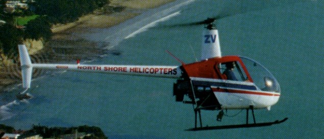
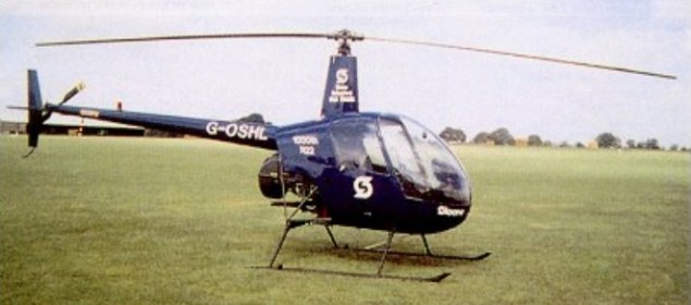
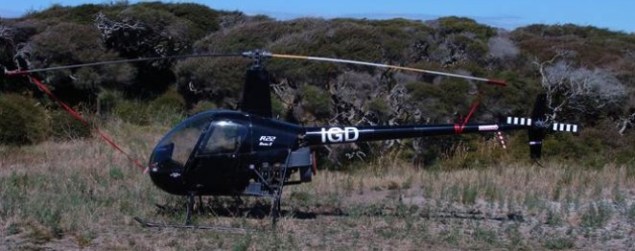
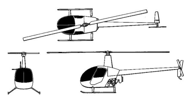
A simple, pod-and-boom light helicopter; horizontal stabiliser, starboard side only; vertical stabiliser above and below boom; offset to starboard; tall rotor mast. Horizontally mounted piston engine drives transmission through multiple V belts and sprag-type overrunning clutch; main and tail gearboxes use spiral bevel gears; maintenance-free flexible couplings of proprietary manufacture used in both main and tail rotor drives. Two-blade semi-articulated main rotor, with tri-hinged underslung rotor head to reduce blade flexing, rotor vibration and control force feedback, and an elastic teeter hinge stop to prevent blade-boom contact when starting or stopping rotor in high winds; blade section NACA 63-015 (modified); two-blade tail rotor on port side; rotor brake standard.
Flying controls are manual. Removable dual controls standard. All-metal bonded blades with stainless steel spar and leading-edge, light alloy skin and light alloy honeycomb filling; frame section of steel tube with light alloy skinning; full monocoque light alloy tailboom. Welded steel tube and light alloy skid landing gear, with energy-absorbing crosstubes.
The basic model, which became known as the R22 Alpha, was replaced from the 501st aircraft onwards, in 1985, by the upengined R22 Beta. Improvements to the R-22 Beta model include uprated 160hp Lycoming O-320-B2C engine, high-capacity oil cooler, improved heater, demister, silencer and rotor brake. This two-seater can cruise at 178km/h and with a twenty US gallon tank of fuel travel for 385km. The Beta was certified on 5 August 1985. The more powerful Textron Lycoming O-360 engine provides better high-level hover performance and allows take-off power to be sustained up to 2,285m. Previously optional, tinted windscreen and door windows were fitted as standard. Production began at c/n 2571.
Despite the company’s small size, Robinson achieved a production rate of about 30 R22s per month, with 402 produced in 1991 alone. There have also been military customers, such as Turkey, who ordered 10 for basic pilot training. Over 2300 R22s of all versions had been delivered by early 1993. Total production of the R22 had exceeded 2,500 aircraft by 1995.
Japanese certification was achieved on 18 November 2002. By September 2003, Robinson had produced 5,000 helicopters, including 390 in 2000, 328 in 2001 and 255 in 2002. Production rate 11 helicopters per week in 2003. Factory floor area 24,150 sq.m. Workforce totals 820. Company is ISO 9001 certified.
The R22 Beta II cost US$170,000 for the basic version in 2003. The engine is mounted in the lower rear section of the main fuselage, with cooling fan. Over the years, Lycoming has been so impressed with the reliability and condition of both the R22 and R44 engines that they actually increased the TBOs to 2,200 hours. Light alloy main fuel tank in upper rear section of the fuselage on port side. Transmission overhaul interval 2,200 hours or 12 years.
Two seats side by side in enclosed cabin, with inertia reel shoulder harness. Curved two-panel, tinted windscreen. Removable door, with tinted window, on each side. Baggage space beneath each seat. Cabin heated and ventilated. Electrical system, powered by 12V DC alternator, includes navigation, panel and map lights, dual landing lights, anti-collision light and battery.
Standard equipment includes rotor brake; tinted windscreen and windows; belly hardpoint; dual landing lights; navigation, panel and map lights; anti-collision light; ground handling wheels; rotor blade tiedowns; and windscreen cover.
Optional equipment includes three-cylinder engine priming system; RHC oil filter; cabin heater/defogger; metallic base or trim exterior colours; and leather seats.
The R22 was purchased by only a couple of military customers, the Turkish Army, in 1992 and Argentina, mainly for use by the Buenos Aires Police.
Variants:
R22 Mariner: fitted with floats and wheels, first delivered for offshore work in Mexico and Venezuela
R22 Police: version with special communications fit and optional port-side controls. Uprated electrical generator for searchlight, loudspeaker, siren and ATC transponder
R22 IFR: training version with improved flight instruments and radio for Instrument Flying Rules operations
External load R22: additional cargo hook certified to carry 181kg underslung load. When fitted aircraft has a VNE (never exceed speed) limit of 139km/h. Conversions undertaken by Classic Helicopter Corp. of Boeing Field, Seattle, Wa.
R22 Agricultural: equipped with low-profile belly hopper and spray-bar system
R-22 Engine: Lycoming O 320-A2B, derated to 124 hp TBO: 2,000 hrs Rotor: Two blade, teetering, 25 ft. dia Length: 21 ft. 10 in Height: 8 ft. 9 in Max ramp weight: 1,300 lbs Max takeoff weight: 1,300 lbs / 621kg Standard empty weight: 790 lbs Max useful load: 510 lbs Payload max fuel: 389 lb Disc loading: 2.6 lb/sq.ft Power loading: 10.5 lb/hp Max usable fuel: 20 USG/120 lbs Max rate of climb, sea level: 1200 fpm Max rate of climb, 5,000 feet: 1060 fpm Max operating altitude: 14,000 ft Max speed: 101 kts Cruise, 65 % power at 8,000 ft: 94 kts Fuel flow at 65 % power: 8 USG/hr Endurance at 65% power, no res: 2.5 hrs Max cruise: 96 kt Max range cruise: 87 kt Range max fuel/ cruise: 108 nm/1.1 hr Range max fuel / range: 118 nm/ 1.4 hr Service ceiling: 14,000 ft Hover in ground effect: 6500 ft Hover out of ground effect: 4500 ft Seats: 2 199 built
R22HP Engine: Lycoming O-320-B2C, 160 hp de-rated to 124 hp TBO: 2000 hrs Main rotor: 25.2 ft Seats: 2 Length: 28.7 ft Height: 8.8 ft Max ramp weight: 1300 lbs Max takeoff weight: 1300 lbs / 621kg Standard empty weight: 800 lbs Max useful load: 500 lbs Zero fuel weight: 1184 lbs Max landing weight: 1300 lbs Disc loading: 2.6 lbs/sq.ft Power loading: 10.5 lbs/hp Max usable fuel: 120 lbs Max rate of climb: 1200 fpm Service ceiling: 14,000 ft Hover in ground effect: 8,300 ft Hover out of ground effect: 6,400 ft Max speed: 102 kts Normal cruise 75% @ 3000 ft: 94 kts Fuel flow @ normal cruise: 48 pph Endurance @ normal cruise: 2.3 hr 151 built
R-22 Alpha Engine: 1 x Textron Lycoming O-320-B2C, 160hp derated to 124 hp Instant pwr: 95 kW Rotor dia: 7.7 m MTOW: 1370 lb, 621 kg Empty wt: 824 lb, 380 kg Useful load: 240 kg Fuel cap: (19.2 gallons) 115 lb, 75 lt Pilot, passenger and Baggage 431 lb Vne: 102 kts Cruise Airspeed 75%: 96 kt Maximum Range (No Reserve) 208 nautical miles ROC @ 53 kt: 1000 fpm HIGE: 6970 ft HOGE: 5200 ft Service ceiling: 14,000 ft Crew: 1 Seats: 2 151 built
R22 Beta Engine: 1 x Textron Lycoming O-320-B2C, 119kW, 131 hp for five minutes and 124 hp continuous Main rotor diameter: 7.67m Length: 6.3m Height: 2.67m Max take-off weight: 621kg Empty weight: 379kg Max speed: 180km/h Ceiling: 4265m Range with max payload: 592km Crew: 1 Passengers: 1
R22 Beta II Engine: Lycoming O-360, 131 hp MTOW: 1370 lb Empty wt: 855 lb Usable fuel capacity: 72.5 lt Optional auxiliary fuel capacity: 39.75 lt HIGE: 9400 ft Max op alt: 14,000 ft
After working for Bell, Kaman, Cessna and then Hughes, Frank Robinson formed Robinson Helicopters in 1971 to design and build a low-cost, piston engined, two-seat lightweight helicopter as the R22, which first flew in August 1975. Deliveries started 1979 and over 2,700 since sold in several versions, including improved R22 Alpha and Beta, Mariner with floats, IFR Trainer for instrument training, Law Enforcement and Agricultural versions. A four-seat development first flown March 1990 as the R44 Astro, with deliveries from 1993. Variants include IFR Trainer, Newscopter for media operations, and Police Helicopter.
1995: 24747 Crenshaw Blvd, Torrance, CA 90505, USA.