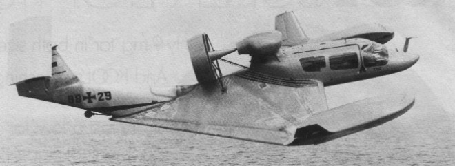
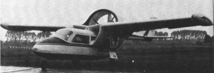
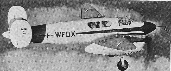
One of the first aircraft designed specifically for Wing In Surface Effect flight, designed by Dr Lippisch, the X-114 could operate in surface effect over waves of 1.5m and was able to escape into unrestricted free-flight. The ground effect craft flys on a bubble of air built up under its reverted negative V delta wing.
VFW Fokker completed preliminary flight testing of its radical RFB X-114 in 1975. It can fly free but is designed to travel over water or flat terrain in ground effect, which gives it a range of almost 1,100 nautical, a duration of 20 hours and a cruise of about 80 knots.
Engine: 1 x Lycoming, 200 hp Cruise: 100+ kt Range: 1000 km Seats: 6 Fuel consump: 1 kg / 10 km
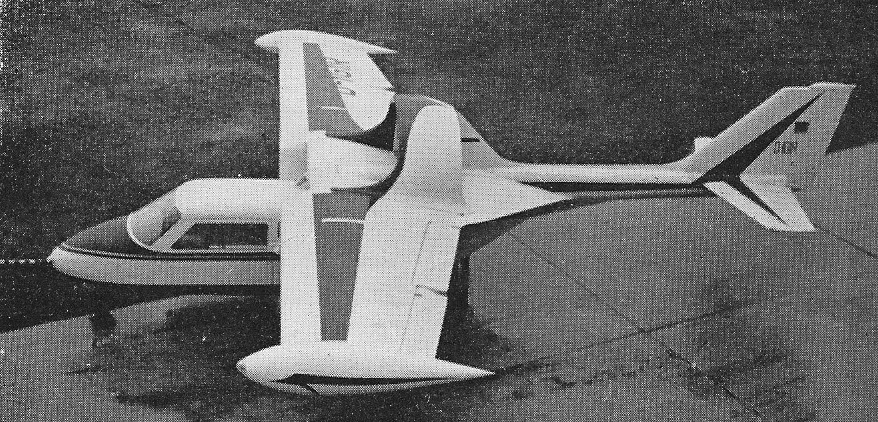
The project was initially a cooperative one with Grumman American, GA supplying wings and empennage, for the most part off the shelf Cheetah parts, and retaining an option to market the airplane in the U.S. RFB has been responsible for design, development and certification. The second prototype embodied improvements in duct and fan technology and a somewhat larger airframe; it was the prototype that will be used for certification in Germany, from which, under reciprocal agreements between the two countries, FAA certification will more or less routinely follow. Grumman declined the marketing option in January 1977, but there is a continuing agreement between the two firms to explore the possibilities of ducted fans.
Luigi Colani ended up designing the entire forward fuselage and cabin a fiberglass and plexiglass shell grafted onto a simple keel upon which the entire airplane is built. The pilot and single passenger recline in an elegantly streamlined shell at the front of the airplane. Behind them is a smallish luggage space precisely like that in a small sports car, right down to the transmission tunnel hump provided by the keel structure. A well padded firewall separates the cabin from the engine compartment, the tubular spar of the GA wing. Wings and gear are from a Grumman Cheetah. Reconfigured from a low wing to a mid body location.
The engine is a two rotor NSU Wankel of 150 horsepower. It is water cooled and uses a double automotive ignition system of the battery/generator/coil/distributor type. The Wankel comfortably delivers its peak power at about 6,000 rpm, and the ducted fan allows it to turn at that speed regardless of the forward speed of the airplane.
Rather than take advantage of the ability of the fan to operate efficiently at high speed to eliminate the need for reduction gearing; RFB found that the noise produced by the small, multi-blade, fast-turning fan was so unbearable that they had to turn to a larger three blade version geared down to turn at about half the speed of the engine.
The fan itself is simply a fixed pitch propeller with broad, stubby blades of rather complicated shape. The optimum design has not yet been found, but it is thought that replacing the blades with a scimitar shaped type will further reduce noise at no cost in thrust. The circular duct enclosing the propeller counteracts the natural inefficiency of a stubby blade, which, like a stubby wing, tends to produce a lot of drag along with its lift.
The engine is cooled by radiators behind and below the cabin, with almost invisible flush air inlets be-neath the aft fuselage, exhaling into the fan duct. Cabin heat (not satisfactory on the prototype) is provided, as in most cars, by pumping some of the engine cooling water through a heat exchanger in the cabin air inlet.
The composite-construction Fantrainer first flew in October 1973 powered by two Wankel rotary engines.
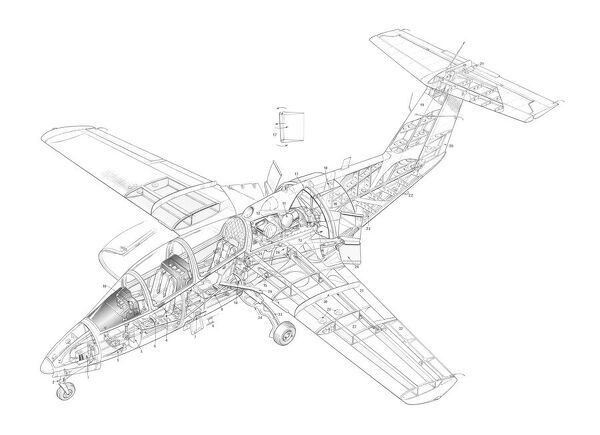
Subsequent aircraft have used a single Allison 250 turboshaft to drive a Dowty Rotol five-blade constant-speed ducted fan. Its 150hp, water cooled Wankel engine drives a 43 inch, three blade, shrouded fan, which is located directly behind the two seat cabin. The tail cone is not a cone; instead, it consists of intersecting vertical and horizontal beams whose caps pass around the fan, and at whose intersection is a slender, tapering tube the “cone”. The empennage is a “T” arrangement with a swept vertical.
The RFB AWI 2 Fantrainer first prototype (98+30) was flown for the first time on 27 October 1977. Two prototypes of this tandem two seat trainer had been ordered by the Federal German defence ministry for evaluation as a potential replacement for the Piaggio P.149D primary trainers in Luftwaffe service.
The RFB Fantrainer, flown in AWI 2 and ATI 2 prototype forms, was in production in 1984 as the Fantrainer 400 and Fantrainer 600 with 420 shp (313 kW) and 650 shp (485 kW) Allison turboshafts for the Royal Thai air force. All but six of the 31 Fantrainer 400s and 16 6Ws were assembled in Thailand.
The Royal Thai Air Force is to receive 31 Fantrainer 400s and 16 more-powerful Fantrainer 600s. All but four are to be assembled in Thailand from kits supplied by RFB but using Thai designed and built metal wings in place of the original GRP units. The Thai aircraft will have four underwing weapons pylons. The first two German-built aircraft were delivered in October 1984, but the license-assembly programme has suffered a number of delays, particularly associated with production of the metal wings. To expedite deliveries, a number of Thai-assembled aircraft have been completed using German-supplied GRP wings. Thai aircraft also have a revised cockpit, Alkan stores management, and Stencel Ranger rocket assisted escape systems.
Two production models were offered, the Fantrainer 400 with the Allison 250-C20B 420 shp engine, and the Fantrainer 600 with a 650 shp Allison 250-C30 power plant.
Lufthansa also selected the type for its pilot training school.
Projected Fantrainer 800 did not enter production; neither did the proposed Tiro-Trainer with a turbofan engine.
Fantrainer 400 Engine: 1 x Allison 250 turboshaft, 420 shp
Fantrainer 600 Engine: 1 x Allison 250-C30 turboshaft, 600 shp Span: 9.7 m Length: 9.5 m Height: 3.2 m Wing area: 150.696 sq.ft / 14 sq.m Empty wt: 2557.8 lb / 1160 kg MTOW: 2300 kg Warload: 800 kg Max speed: 430 kph Landing speed: 61 kts / 113 km/h Cruising speed: 200 kts / 370 km/h Initial ROC: 960 m / min / 2952.76 ft/min / 15.0 m/s Service Ceiling: 25000 ft / 7620 m T/O run: 200 m Ldg run: 270 m Fuel internal: 475 lt Range: 1390 km Endurance: 4.8 hr Crew: 2
RFB built and flew the RF1 six-seat STOL transport in 1960, with two Lycoming engines geared to drive single pusher propeller in a wide-chord duct above the rear fuselage.
Founded in 1957, RFB obtained a license from Rhein-West Flug to build the RW-3 Multoplane in 1957, flying the first production aircraft in 1958 and following with a small batch.
Built and flew the RF1 six-seat STOL transport in 1960; with two Lycoming engines geared to drive single pusher propeller in a wide-chord duct.
In 1968, VFW-Fokker acquired 65% of shares in RFB, and in 1969 RFB acquired a percentage holding in Sportavia company. Company became busy with military contracts for overhaul, and target towing for some years.
Built in collaboration with Grumman-American the Fanliner two-seat light aircraft with Wankel rotary engine, first flown in 1973. It was re-engined in 1976 with a Dowty Rotol ducted propulsor. Based on the Fanliner’s promise, the Federal German Government awarded a contract for two Fantrainer prototypes with ducted fan engines, first flown in 1977 and 1978. In the 1970s German interest in general aviation was maintained by one or two smaller companies, but there has also been quite a large R&D investment by Rhein Flugzeugbau, in ducted fan propulsion for a new generation of lightplanes represent¬ed by its Fanliner.
Production Fantrainer 400s and 600s were ordered only by Thailand, the first (a 600) flying in 1984 and most assembled in Thailand from kits. Projected Fantrainer 800 did not enter production; neither did the proposed Tiro-Trainer with a turbofan engine. Company ceased trading in 1997.
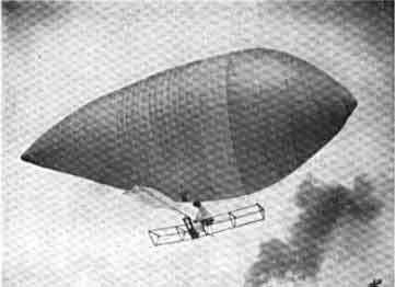
Baldwin’s Aerial Rowboat proved a remunerative attraction, though a short-lived one: One night its hydrogen inexplicably ignited, destroying the craft.
That didn’t deter Alva L. Reynolds from launching his own version at nearby Fiesta Park the same year. Thirty-four feet long and 14 feet in diameter, Man Angel had a four- by 10-foot wooden gondola, a 3,000-cubic-foot gas envelope, and a weight of only 18 pounds. Like Baldwin’s craft, it was propelled by oars.
The earliest of six neutral-buoyancy man-powered dirigibles designed and built by Alva L. Reynolds of Los Angeles, California, trials performed above Fiesta Park, Los Angeles, where the aerial rowboat was first flown by Herbert Burke on July 27, 1905.
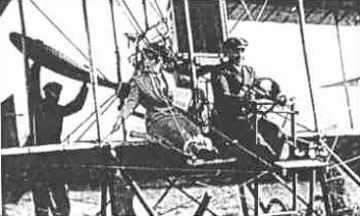
Reynolds claimed that just about anyone could operate Man Angel. To prove it, he allowed 17-year-old Hazel Odell to take the helm. According to a reporter at the Los Angeles Herald Examiner:
“Miss Odell entered the car and…raised herself to 100 feet. After slight effort she was able to propel the airship in any direction and control its ascent and descent at will. When asked for her motive for performing the feat Miss Odell said: ‘Why should I not? Other people have done it and I was not afraid.’ ”
Reynolds built six Man Angels and leased them to fairs in Kansas, Arizona, and Texas. He also opened a flying school, where he gave twice-daily demonstrations.
Man Angel No.2
The 1905 “Man Angel” hydrogen-filled balloon was 34 feet long and carried an 18 pound frame in which a man sat using ten foot long oars to row across the sky.
Man Angel No.2
The U.S. government investigated purchasing one.
That October, Reynolds challenged Baldwin to an airship race. When Baldwin’s pilot, the balloonist Roy Knabenshue, asked for $20,000 in expense money, Reynolds said Knabenshue was “afraid to race.” In 1906, to keep up interest (and revenue), Reynolds challenged an automobile to a 30-mile race from Chutes Park to Pomona. So confident was Reynolds that Man Angel No. 6 would win, he gave the Herald Examiner $1,000 to hold as prize money. On the day of the race, Man Angel faced such strong head winds it was handily beaten. In a subsequent race, the airship got caught on a telephone wire and crashed into a treetop.
Reynolds never raced Man Angel again. He returned to inventing, and found a method for generating electricity from ocean waves.
The Reynard R.4 Primary was an open seat primary glider with an open girder fuselage and a high, wire braced wing.
The wing was rectangular in plan, with ailerons at the tips but no flaps or airbrakes. N-form struts from the wing supported a girder about 8.5 ft (2.6 m) long and curved on the underside to form a landing skid. The pilot’s seat and controls were placed, exposed, on its upper surface just ahead of the wing. Lift wires ran from this girder to the underside of the wing beyond mid-span and a pair of landing wires on each side were fixed to the apex of a two strut, triangular central cabane or kingpost above the wing.
Behind the wing trailing edge and the end of the lower girder the rear fuselage was a tapering, vertically orientated, two bay Warren truss, ending at a vertical cross member which supported the rudder. The triangular tailplane and fin were mounted on the horizontal upper fuselage beam and the straight edged rudder extended down through a cut-out between the elevators to the lower beam.
It was designed and at least five built in the UK in 1930 by Reynard Gliders, Leicester. Some Reynards were built with a hinged nacelle to give the pilot better protection from the weather, though still in an open cockpit. To compensate for the extra side area the rear two bays of the fuselage were fabric covered.
It has been suggested that at least two R.4s were built with steel tubed rather than wooden rear fuselages, under the name Reynolds R.4 after the contemporary bicycle tube frame manufacturer.
The Reynard could be bought complete for £45 or built from plans costing 21/- (1 guinea or £1.05) and was regularly advertised in 1930-1. Several were built and active in the early 1930s with UK gliding clubs. One was demonstrated to the Leeds club in October 1930 and they received the first of two the following month. The Bradford, Halifax, Leicester and Ulster Gliding Clubs also had Reynards.
The two Reynards that received BGA certificates of airworthiness, BGA 166 and 167 had serial number R.4/5 and R.4/6 respectively BGA 166 was used by the Leeds and later Bradford Gliding Clubs. BGA 167 was used by the Ulster Gliding Club from 1931, they fitted a nacelle when they rebuilt it aircraft in 1933. This glider went to the Dublin Gliding Club in 1934 and was still active the following year.
Wingspan: 34 ft 2 in (10.41 m) Aspect ratio: 6.6 Length: 18 ft 3 in (5.56 m) Height: 7 ft 2 in (2.18 m) Crew: 1
The Reynard Glider Construction Co of Aylestone, Leicester, UK, built a few primary gliders, of an original design, in 1930. The company last advertised in the “Sailplane and Glider” dated 6 February 1931.
The R-1 was an experimental twin-engine monoplane with variable- incidence wings, first flown with normal wings on 16 December 1949, and with articulated wings in 1951.
Original patents taken out in 1938 and an aircraft built in 1940, but was destroyed during the war. Two prototypes were built, of wooden construction, powered by two Renault 6R engines.
The outer wing panels are articulated on an oblique hinge-line and these orientate automatically in turbulent air, the varying incidence absorbing the loads imposed.
Engines: two Renault 6R, 216 hp Wingspan: 43 ft 2.5 in Length: 30 ft 2 in Height: 11 ft 11 in Empty weight: 4950 lb Loaded weight: 6490 lb Max speed: 202 mph Time to 3280 ft: 4 min 10 sec Ceiling: 19,025 ft
France Built experimental R-1 twin-engine monoplane with variable- incidence wings, first flown with normal wings in 1949, and with articulated wings in 1951. Original patents taken out in 1938 and an aircraft built in 1940, but was destroyed during the war.
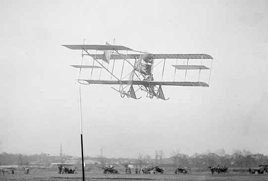
Designed by Rex Smith and Frederick Fox, the Rex Smith Biplane Curtiss-type first flew on 5 November 1910, piloted by R Smith. It was built and demonstrated at College Park, Maryland, at the same airfield that the Wright Brothers trained pilots using their aircraft for the U.S. Army Signal Corps just north of Washington, D.C.
This followed the initial demonstration at Fort Myer, Virginia, in 1908 and 1909, when the U.S. Army Signal Corps accepted the Wright Flyer in July 1909. Both the Wright Brothers and Curtiss continued to demonstrate their aircraft at the College Park Airport.
A two-place biplane powered by an Emerson marine engine pusher, it was used in Signal Corps experiments with wireless radio-telegraphy in April 1911, piloted by Antony Jannus.
Rex Smith Tony Jannus piloting
At a 1911 display in Washington, D.C., of the Smith biplane, a large crowd gathered to watch the motor started indoors, kicking dust throughout the building. On April 13, the biplane demonstrated wireless air-to-ground communications at College Park. On April 15, test pilot Tony Jannus attempted a take-off from the Potomac River with new pontoons attached to the landing skids. The plane plowed into the water, nearly drowning Jannus. By the end of the year, the aircraft had demonstrated 137 flights, including takeoffs and landings during snowstorms.
An aircraft was developed with an airfoil that tapered from four feet thick to nearly flat at the wingtips. The aircraft used wing warping tips rather than ailerons. It was tested with a Hall-Scott engine by test pilot Paul Peck. A Berliner Rotary was also considered for the design.
Rex Smith Biplane Powerplant: 1 × Emerson 2 cycle, six cylinder, 100 hp (75 kW) Propeller: 2-bladed Paragon, 9 ft (2.7 m) diameter Wingspan: 40 ft (12 m) span later reduced to 32 feet for speed Empty weight: 875 lb (397 kg) Capacity: 1-3