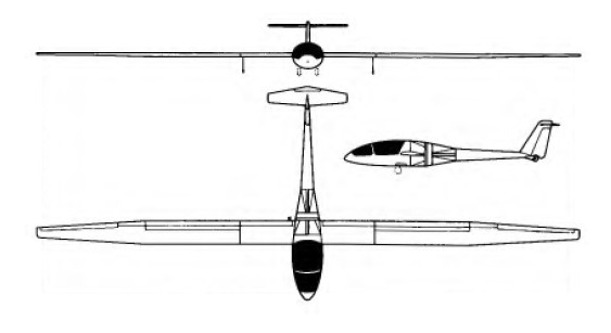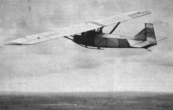
Rhӧn-Rossiten-Gesellschaft / RRG Prüfling

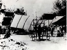
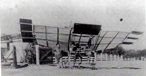
At the end of 1925 at the Martens gliding school on the Wasserkuppe into Rhön-Rossitten Gesellschaft (RRG), Martens chief instructor Fritz Stamer and Alexander Lippisch were brought together to produce two such gliders and within a few days the Zögling (English: Pupil) and the Prufling designs were complete. Some parts, for example the wings and to a lesser extent the horizontal tails, of the two aircraft were similar.

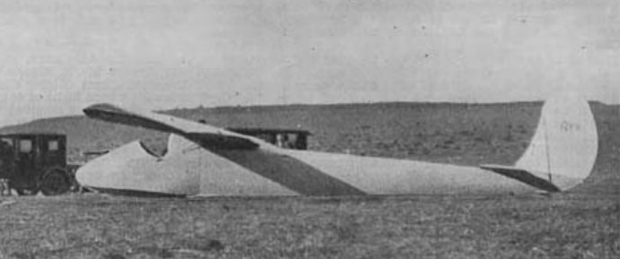
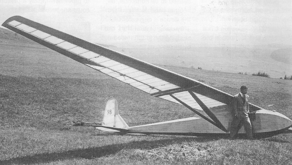
Both had almost rectangular, two-spar, wooden structured, two piece wings with fabric covering everywhere except the leading edges, which were plywood covered. The Prüfling’s wing tips were more rounded and its span 500 mm (19.7 in) greater. They both had simple ailerons reaching to the tips, where they were cropped, though the Prüfling’s were a little longer. Both had triangular tailplanes, carrying elevators that were rectangular apart for a cut-out for rudder movement, though the Prüfling’s tailplane was more strongly swept and was broader in chord.

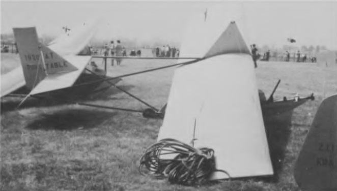
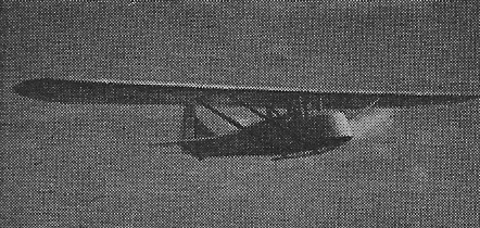
The major differences between the two were in the fuselages. The Zögling had a very simple open frame girder fuselage, the Prüfling a more conventional hexagonal cross section, wood-framed structure, ply covered forward from under the wing and fabric covered aft. The wing was supported over the fuselage with a pair of parallel lift struts on each side, bracing it at almost mid-span at the spars to the lower fuselage longerons. The open cockpit was below the wing centre section which was supported by two pairs of cabane struts to the upper fuselage longerons. The forward pair, placed just in front of the cockpit were single, upright struts but the rear ones, just behind, were each an inverted V-pair. At the centre there was a noticeable gap between the wings, bridged by a short chord wooden link. The horizontal tail was positioned on the upper longerons. with a triangular fin carrying an upright, straight edged balanced rudder which was slightly angled below the heel and extended down to the keel. The Prüfling landed on a rubber sprung skid below the whole forward, ply skinned fuselage, assisted by a very small tailskid.
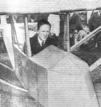
It first flew in 1926 and was soon in use with the RRG related Rhön and Rossitten gliding clubs. Plans were sold and many were built inside and outside Germany.[ As examples, one was flying with the Lancashire Aero Club and another with the London Gliding Club in the early 1930s. Despite such success, the Prüfling was something of a disappointment as a secondary training aircraft, for its performance was not much better than typical primaries. Its handling was also not good, with a lack of inherent stability. Lippisch returned to the design of secondary gliders four years later, after exploring tailless types, resulting in the RRG Falke.
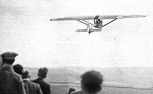
A Prüfling was the first glider used by the United States Navy. A single German-made aircraft was purchased from a U.S. civil glider school, assigned serial number A8546, and used for airship launch tests; the first such launch was made from USS Los Angeles (ZR-3) on 31 January 1930. The Prüfling was never assigned a formal U.S. military aircraft designation.
Wingspan: 10.50 m (34 ft 5 in)
Wing area: 15.24 sq.m (164.0 sq ft)
Length: 5.484 m (18 ft 0 in)
Aspect ratio: 7.23
Empty weight: 105 kg (231 lb)
Gross weight: 195 kg (430 lb)
Wing loading: 12.8 kg/m2 (2.6 lb/sq ft)
Capacity: One

1938 Proefling
Wingspan: 42 ft
Length: 19.5 ft
Wing area: 230 sq.ft
Aspect ratio: 7.7
Empty weight: 320 lb
Gross weight: 500 lb
Mn sink: 3 ft/sec
Glide ratio: 15-1
Rhein-West RW-3 Multoplane / Fischer RW-3

Fischer RW-3

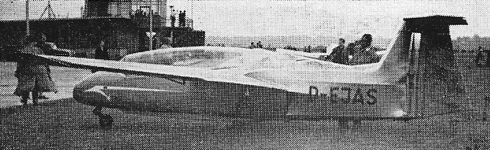
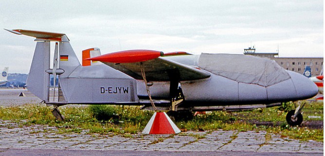
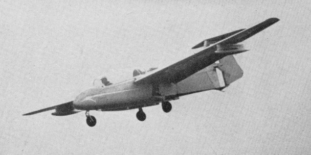
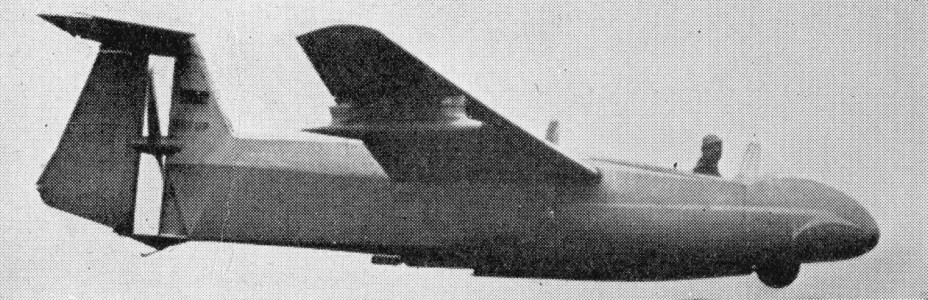
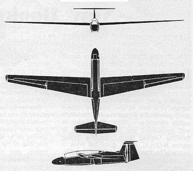
The Fischer RW-3 was essentially a powered glider of mixed wood and metal construction, with fabric covering. The cantilever mid-wing is swept forward while the T-tail assembly acts as a mount for the propeller. The main wheels are retractable manually as is the semi-retractable nose wheel.

The first prototype RW-3 A-1, D-EJAS, was wrecked in June 1956 and a second was built.

RFB RW3-P75 Multoplan

RWF formed at Porz-Westhoven, near Cologne, in early 1950s to develop a new light aircraft, the RW-3 Multoplane, basically a powered sailplane with Porsche engine driving a propeller mounted between the fin and rudder, and under the tailplane. The production license was subsequently transferred to Rhein-Flugzeugbau GmbH.
It is powered with a Porsche 678/4 aircraft powerplant, a flat-four opposed piston engine with a reduction gearing of 1.981, a takeoff-power rating of 75 hp at 4600 rpm (propeller 2320 rpm), and max continuous power rating of 65 hp at 4500 rpm (propeller 2070 rpm). Leaned out, it delivers 55 hp at 4100 rpm (propeller 2070 rpm), with fuel consumption in economy flight mode 3.7 US gph.

This RW-3 Multoplane was demonstrated in England during August 1958.

Gallery

RW-3 A-1
Engine: Porche 55 hp
Wingspan: 48 ft 6.5 in
Length: 23 ft 11.5 in
Wing area: 188.4 sq.ft
Aspect ratio: 15.4
Empty weight: 795 lb
Loaded weight: 1235 lb
Max speed: 103 mph
Cruise: 90 mph
Best glide: 22
Min sink: 2.95 ft/sec

Fischer RW-3

Rhein-West Flug

Germany
RWF was formed at Porz-Westhoven, near Cologne, in early 1950s to develop a new light aircraft, the RW-3 Multoplane, basically a powered sailplane with Porsche engine driving a propeller mounted between the fin and rudder, and under the tailplane. The production license was subsequently transferred to Rhein-Flugzeugbau GmbH.

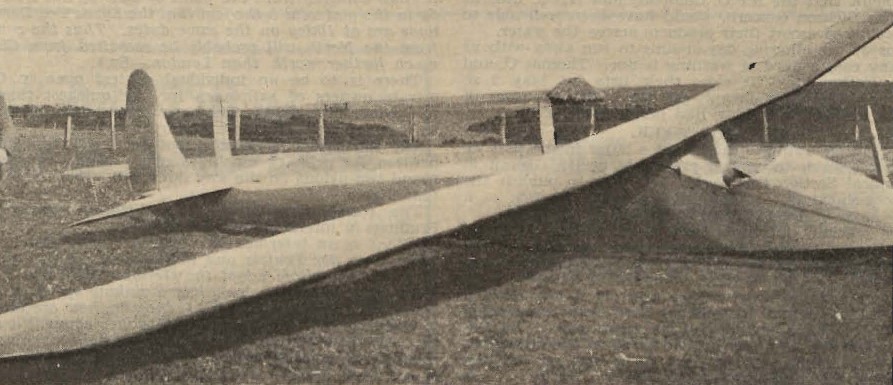
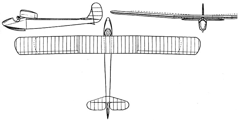
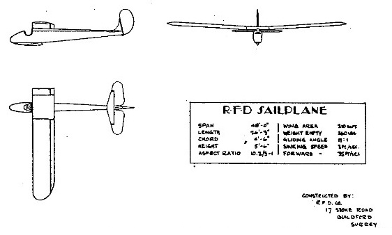
R.F.D. 2

Named for design lead Reginald Foster Dagnall, the all-wood R.F.D. 2’s unusual dual span cantilever wing had outer sections with constant chord, slight sweep, blunt tips and full width ailerons, joined by a choice of two rectangular centre sections. The sailplane centre section was about 15 ft (4.57 m) long, reduced to about 5 ft (1.52 m) for the secondary trainer role. The wing was not fitted with flaps or airbrakes.

The fuselage of the R.F.D. 2 was a flat-sided monocoque with the wing mounted directly on top of it. The single seat open cockpit was immediately ahead of the wing leading edge. The main landing skid ran from the nose to about mid-chord and there was a small tail skid. The triangular tailplane, mounted on top of the fuselage, and curved fin were both small but carried generous, curved edged control surfaces. The rudder extended to the bottom of the fuselage, moving between the elevators.

The R.F.D. 2 first flew in February 1931 but seems not to have received certification or registration. Only one had been built when, in January 1932, the R.F.D. company announced it was selling its glider interests to the British Aircraft Company and would concentrate on its products for the Air Ministry.

Wingspan: 48 ft 0 in (14.63 m) long span; short span 38 ft 0 in (11.58 m)
Wing area: 210.0 sq ft (19.51 m2) long span; short span 165 sq ft (15.33 sq m)
Aspect ratio: Long span 11.0; short span 8.45
Length: 26 ft 3 in (8.00 m)
Empty weight: 250 lb (113 kg) long span; short span 215 lb (97.5 kg)
Gross weight: 410 lb (186 kg) long span
Rate of sink: 120 ft/min (0.61 m/s) maximum, long span; short span 150 ft/min (0.76 m/s)
Lift-to-drag: Minimum, long span 23.4 at 32 mph (51 km/h); short span 20.4 at 34.7 mph (55 km/h)
Wing loading: 1.85 lb/sq ft (9.0 kg/m2) long span

R.F.D. T.3 Dagling / Slingsby T3 Primary / Dagnell-Brewsher Primary / Dart Zogling

Slingsby Dagling

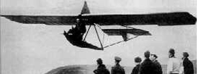
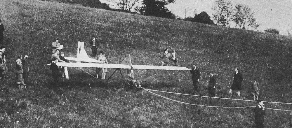
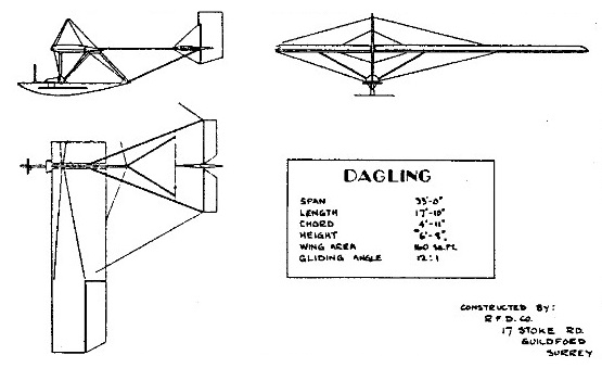
Primary training gliders evolved as very simple, even crude, airframes sufficiently basic and strong to withstand the rough handling of inexperienced beginner pilots while having just enough flying ability (and vices) to give the trainee pilot the feel of the controls and enable him to grasp the basic skill of controlling an aircraft in flight. The best known British prewar example in this category was the Dagling, a primary glider the prototype of which was built in 1930 by R. F. Dagnall, founder of the R.F.D. Co Ltd, for the London Gliding Club using plans acquired through America; this was a version of the German Zogling primary, and the combination of ‘Dagnall’ and ‘Zogling’ resulted in the name Dagling, which was often later applied to all primary gliders regardless of their true identity.

The Dagling had a low aspect ratio constant chord wing from which a rudimentary wooden A-frame fuselage framework was suspended housing the pilot, the tail unit being carried on four steel tubular members – these had
been wooden members in the Zogling, but were changed to metal to give a stronger support for the tail. Simple wood and fabric construction was employed, with wire-braced wings and only a main skid on the bottom fuselage member for the landing gear. Some Daglings had a nacelle fitted to give the pilot some protection from the elements, while others had rounded instead of squared-off wing tips, and at least one had a nacelle with two seats in it.

Although pretty basic, the Dagling was successful enough to go into production and the R.F.D. Co built at least 27 but in January 1932 announced the cessation of its glider making activities to concentrate on its Air Ministry contracts.

Dagling production was taken up by several other British firms, the foremost of which was Slingsby, which started building the type at Scarborough in 1933 as the T3 Primary, and eventually built 67; Slingsby’s 1933 price for a complete Dagling was £45, and this had risen to £57 15s (£57.75) by 1939, or £66 with a nacelle. For amateur constructors, the British Gliding Association offered a complete set of Dagling plans in 1933 for only £2. Dagling production was also undertaken by Hawkridge Aircraft Ltd, who built five after the war, by Dart Aircraft Ltd, by the Dunstable Sailplane Co, who built one, and Abbott Baynes Sailplanes Ltd; the type’s simplicity also enabled it to be built by students at technical schools and colleges such as the College of Aeronautical Engineering, who built one at Redhill.

The Dagnell-Brewsher Primary was allocated C. of A. No. BGA 171.

The Dart Zogling was built from the same plans as the RFD Dagling.

Several other nations produced single-seater primary types in the 1930s basically similar in appearance and performance to the Dagling, such as the Italian Allievo Pavullo, also available with or without a nacelle, the US-designed Denver Primary and the German Schulgleiter SG 38 (the 108-14) and the Grunau Ei.

Slingsby T3 Primary
Span: 33 ft 0 in
Span: 33 ft 11.5 in (with rounded tips)
Wing area: 15.06 sq.m / 162 sq.ft
Aspect ratio: 7.1
Length: 17 ft 10.5 in
Empty Weight: 82 kg / 180 lb
Payload: 91 kg / 200 lb
Gross Weight: 173 kg / 380 lb
Wing Load: 11.5 kg/sq.m / 2.35 lb/sq.ft
Stalling speed: 25 mph
No. of Seats: 1

R.F.D. Co Ltd / Dagnall, R.F.

Reginald Foster Dagnall was born in Fulham, London on 11 April 1888 the son of Walter and Frances Dagnall, he was educated at Tiffin School, Kingston upon Thames. Dagnall started his career in the drawing office of the Thames Ironworks and Shipbuilding Company. He then joined Ernest Willows in developing Willows airships and during the 1914-18 war he was first works manager and then general manager of Airships Limited., a firm which made kite balloons and blimps.

After World War I Dagnall founded his own company, in a small factory at 17 Stoke Road, Guildford, Surrey Dagnall began the manufacture of equipment and gliders.

The RFD name is now synonymous with “Rapid Flotation Device” and the supply of marine and aviation safety equipment. He had researched flotation gear of various sorts, and in 1918 he built some of the earliest rubber dinghies.

RFD moved to Guildford in 1926 and expanded to Catteshall Lane, Godalming, in 1936 the Godalming factory burnt down and was rebuilt in 1954.

The R.F.D. Co Ltd built the prototype of the Dagling, a primary glider, in 1930 for the London Gliding Club using plans acquired through America. Dagnall was a keen glider pilot and chairman of the Surrey Gliding Club and its later incarnation the Southern Counties Soaring Club.

The non-rigid airship AD1 (registration G-FAAX) was designed by RFD and built by the Airship Development Company at the Stoke Road works in Guildford. It was taken to the old Cramlington Airship Station near Newcastle and erected in the 1918 airship hangar, with its first flight on 18 September 1929. In May 1930 it performed a number of aerial advertising flights with banners laced to the envelope sides. The original ABC Hornet engine was replaced by a 75 hp Rolls-Royce Hawk in July 1930 for work in Belgium. By mid-1931 it was dismantled and parts sold off by auction on 18 June 1931.

The Dagling was successful enough to go into production and the R.F.D. Co built at least 27 but in January 1932 announced the cessation of its glider making activities to concentrate on its Air Ministry contracts, and the name of R.F.D. was henceforth to become far better known for liferafts, dinghies, parachutes, air and sea rescue equipment and related products.

Reginald Foster Dagnall died on 16 November 1942 (aged 54) in Surrey, England, of heart failure.

In 1959 RFD merged with Perseverance Mill. In 1963 it took over Elliot Equipment and acquired GQ Parachute Company Ltd. Dagnall was also a director of G.Q. Parachute Co., Ltd., which leased space in the RFD works in Guildford. It purchased Mills Equipment Company in 1968. In 1970 the three companies merged to form RFD-GQ In 1975 RFD-GQ divided into: – RFD Inflatables Ltd – GQ Parachutes Ltd – RFD Systems Engineering Ltd – RFD Mills Equipment Ltd.

RFB / Rhein-Flugzeugbau Sirius

Sirius 2

The Sirius 1 was developed to investigate the efficiency of the ducted fan as a means of propulsion for motor gliders. It was developed from the VFW FK-3 all-metal sailplane and was first powered by a Nelson 48 hp two-stroke engine, then by two Yamaha motor cycle engines and finally two 20 hp Fichtel & Sachs Wankel engines were chosen.

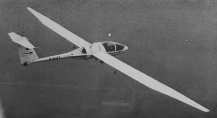
First flown in January 1972, the Sirius 2 is the two-seat companion to the Sirius 1, but Rhein-Flugzeugbau, the manufacturers, in this case have arranged with Caproni of Italy to use the wings, tail unit and landing gear of the A-21 Calif. This side-by-side two-seat ducted fan motor glider is powered by two 30 hp Wankel rotary engines which drive a ducted fan embedded in the fuselage just aft of the wing trailing edge. One engine is mounted in front of the fan and the other behind it. The fan shroud utilises an annular slat intake round the wing leading edge to keep the airflow attached to the duct, and suck-in doors fair off this intake when the power plant is not operating to maintain gliding performance.

Sirius 2
Engines: 2 x Wankel driving ducted fan
Wing span: 20.38 m / 66 ft 10 in
Length: 8.04 m / 26 ft 4.5 in
Height: 1.8m / 5ft 11 in
Wing area: 16.1 sq.m / 173 sq ft
Wing section: Wortmann FX-67-K-170/60-126
Aspect ratio: 25.8
Empty weight: 510 kg / 1,124 lb
Max weight: 690 kg / 1,521 lb
Water ballast: None
Max wing loading: 43.4 kg/sq.m / 8.88 lb/sq ft
Max speed (powered): 146 kt / 270 km/h
Stalling speed: 39 kt / 72 km/h
Min sinking speed: 0.6 m/sec / 2 ft/sec
Best glide ratio: 38
T-O run: 200 m / 656 ft
Rate of climb: 120 m/min / 394 ft/min
Range: 270km / 147nm

Sirius 2