The design goal for the FVA-11 was for the “ideal aircraft” with good glide ratio and low landing speed. Primarily the demand for the cruising speed of 80 kph and an optimal glide efficiency.
The aim was for reasonable rates of descent even at 50 kph and that the landing speed, as a measure of security against crash landings, came as close as possible in 40 kph.
The most difficult demands were the glide ratio and cruise speed. To fulfill this, all residual resistance had to be kept as small as possible and the use of thin airfoils was required. This brought his hand back significant construction difficulties. It was found that the demands for sinking speed and glide could be met with a wingspan of 18 m. However, with the wing load of 21 kg/m² was not able to fall below a minimum speed of 56 kph.
It was necessary for a landing aid be used not only for a sufficient increase in lift, but also with minimal additional drag. The best solution at the time appeared to be Fowler flaps 30% depth in the infield between fuselage and aileron, while in the outer wing, the ailerons simultaneously in a new zero position.
The elaborate fittings for guiding the auxiliary wings were mounted on the underside of the wing. In order not to get too much drag with separate ailerons, the ailerons were designed so that they did not make any further downward deflection, but comes up to full swings.
In order to obtain sufficient documentation for performance and stability calculations, it was decided to examine the proposed flaps in the Aachen wind tunnel. The model was carried out in our workshop. The flap arrangement was such that the flap was able to be adjusted from 0 to 40° in 5° increments. For all these flap positions comparisons were made. The results confirmed the design. The landing speed of 42 kph was reached and the acceptable rates of descent at 50 kph were achieved. The lowest Sink rate rose from 0.6 to 0.7 m/sec.
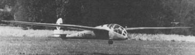
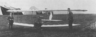
With the construction of the machine started at the end of February 1938, on the first day of the Rhön competition it was flown in Aachen. The test-flight happened by aerotow.
The FVA flew the “Eifel” to the Rhön competition, but the aircraft was flown there but not much. This was mainly because the FVA-11 was not yet ready for competition, still brand new and with its complicated and untried wings. In addition, at this competition there were substantial highs, and to go with an untried wings in cumulonimbus clouds, appeared not appropriate. The accidents that existed during this competition justified this view.
Contrary to the views expressed in the Annual Report 1938/39 hope some planned changes to the FVA-11 were not completed by August 1939 and the machine was destroyed during World War 2.
After the success with the FVA-9 “Blaue Maus II”, in 1935, Benno Sann, Walter Trapp, Artur ghetto and August Schulte began a development with a view of flight performance with the construction of the FVA-10.
A cantilever gull wing was designed for a mid-wing position. The installation was simple with each surface mounted separately to the canopy. On each side three bolts were screwed in from the outside, while the aileron and spoiler automatically joined. It was believed it chould be assembled by three persons, unloaded and ready unassisted in five minutes.
The wing had trapezoidal plan and is, from root to tip, Jukowski 433 , Göttingen 532 and US M 3 profiles. The wings had torsionally stiff wing leading edge, an I-section, spar caps and all other locally stressed components made of hardened wood. The brakes were only on the upper wing surface within the ailerons.
The forward fuselage was built as an open, double-walled shell. The fuselage in steel tube and fabric covered.
The tail boom was a rigid tube without frames, with slight stiffening rings. The elevator was fastened with three externally accessible bolts. As the fuselage was extremely tight, it was decided to incorporate an unconventional handwheel control.
The FVA – 10 was completed in late summer 1936 and given the name “Theodor bees”. The first flight took place in Merzbrück still without a canopy.
Immediately after the first test flights, conducted by Felix Kracht , it was taken to the first Alpine gliding Try to Prien (Chiemsee). There, the canopy was completed. The first longer flights in the foothills of the Alps showed that the performance and handling characteristics were excellent.
e FVA-10a with improvements to the fuselage and wings were completed 1937. In the fall of 1936, the design of the FVA-10b started with a new fuselage and some improvements on the wings. In addition, some new details such as airbrakes on the top and bottom, retractable landing gear with low-pressure tires, brakes and shock absorbers were fitted. A normal joystick control was provided instead of the handwheel control. The goal was to design a new hull shape to allow easy landing at minimum speed with or without brakes.
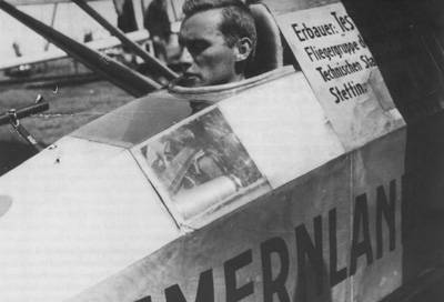
This work was carried out in 1936/37 in Merzbrück and at the same time the new aircraft built in the workshop. This machine received the type designation FVA-10b and the name “Rhineland”.
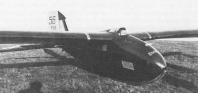
FVA 10b
The first flight of the “Rhineland” was in Merzbrück on May 13, 1937. Immediately after the first flights, the FVA-10a and the “b” were loaded into the transport vehicle shipped first to Prien and then to Salzburg.
It was here in 1937 an international gliding competition was held at the Felix Kracht ND the Rhineland participated. From Salzburg also on 30 May 1937 he succeeded the first alpine crossing in the glider, which he finished at Udine.
Here is an excerpt from the report of Felix Kracht to his crossing of the Alps:
“Even in the Progress Report on the last year’s test flying I had proposed to fly the Mölltal Ainring or Salzburg on the Lattengebirge or watzmann because I was there better thermal conditions suspected as the area south Prien. This assumption has definitely confirmed. In particular, it is there much easier to come from the foothills terrain in the mountains.
So I latched on 29/05/37 in only about 450m from Salzburg airport and flew from there on the west side of the mountain over the Lattengebirge.
About the Ramsau it went between Reiteralpe and hochkalter into Salachtal. The cloud base was at the Alpe rider at 1900 to 2000m, but rose to the central ridge towards continuing.
On this day there was light northerly flow so that stood on the north side of the high Tauem a closed cloud cover, while in the Southern Alps, there was wonderful soaring weather.
Since I was aware of these conditions, I flew because of low cloud base first pass at the lowest (Mallnitzer col) to get there through the Mölltal further south. But this pass was in clouds. Since I wanted to reach the south side of the Tauern because of the good weather, I flew westward in turn, each Tauern passes (Hochtor, Emperor Tauern, Felbertauernstraße) and west of the Great Venice the Birnlücke, so flew 80 km in length, the Tauem along without However, to find a cloud free pass. Since it had become 16h, I broke here from the flight and flew back to the airport customs am See (flight time 5 h 13 min).
The following day was almost the same conditions, but without traffic jams Cloudiness and much higher cloud base (3200 to 4000 m). After trying the morning to fly from 350 m height of release into the mountains, an attempt that I would have paid almost forced landing, I started to 13.30 clock a second time and unlatched tender pursuant out at 800 m above Salzburg on the lower mountain and reached stretched the glide Reiteralpe 3000 m above the valley. There I brought the interaction of sunlight and wind slope with over 6 meters per second up to the cloud base , is 300 meters away.
Then I flew to the south side of the High Cold and from there via Saalfelden fast gliding inches at the lake.
There I reached over Schmittenhöhebahn again the cloud base at 3200 m and flew from here under a cloud street with around 100 km/h southeast to Wörth and flew over 3700 m in the Tauern Hochtor. There I reached a Cloud series, which stood above the Mölltal, almost without curves along which I flew to the Dolomites. (Average altitude 3500 m).
From then on it was in a stretched Gleitlug about Koetschach, Cervicento, Tolmezzo Tolmezzo into Tagliamemotal I flew in 2800 m and came here in the foothills of the Alps standing before storm. In order not to have to fly blind, I gave away my level up to 1100 m (800 m above sea level. Basic and tried to reach the 25 kilometers distant airfield (Udine).
This, however, did not succeed and I ended up in the river Tagliamento (flight time 3 hours 56 minutes).”
Subsequently, the FVA-10b went in July 1937 to the Rhön competition, and Felix Kracht was second behind Ludwig Karch (Section Munich) on Mü 10 Milan. However, the FVA-10b won the award for advanced design.
FVA 10B Rhineland Length: 23.097 ft / 7.04 m Height: 3.182 ft / 0.97 m Wingspan: 52.493 ft / 16.0 m MTOW: 529.2 lb / 240.0 kg Glide ratio: 28.0 Crew: 1
After concentration on powered flight, a new FVA glider, designed by Hans Sander and Karl Doetsch, was completed in 1933. They designed a slight thermal glider, where not only emphasis was placed on the lowest possible rate of descent, but also good speed performance and control engineering properties. At that time the thermals aviation was still in its infancy and theories to optimize distance flights were new.
The FVA-9 is thought by the Akaflieg Aachen as a pure thermal glider with aerotow, tested on a model in a wind tunnel at Aachen. The design and the experiments were carried out in the past winter months, the construction started at the end of April. It offered no special difficulties as a result of careful design work and drawing sufficient material.
The wing has a planked nose with diagonal plywood. The body ends in a torque tube. The elevator is self-supporting and rests on a structure that grows out of the fuselage. The fittings are bent from sheet steel and welded. The operation of the rudder is done with control cables, the ailerons with bumpers and control cables.
The surfaces were produced on a slipway vertical wing building. A special jig built for the hull. When planking the use of nail strip was avoided, instead retaining straps used.
The machine was completed in mid-July and tried during the Rhön competition.
The “MS II” was designed by Hermann Mayer using the principle of achieving good performance as simple as possible:
“She has done outstanding work in various slopes and cross-country flights under the leadership of the designer, especially the maneuverability and the quiet location of the engine in the air are surprisingly good, as evidenced by the long, rectangular body, the large rudder and the generously dimensioned ailerons can be explained.
From last year’s machine (“MI”) of the hull, rudder and mitigating have been adopted. The wing could at the wide span of 20m from running rectangular, but the outer wing take outwardly from a straight line. The wing is with torsion plywood nose and auxiliary spar.” Flugsport 1930, Nr. 17
Completed 1930, it was designed based on the principle of the “M 1” with some improvements, in particular, the wingspan was increased to 20m.
Just as with the FVA-7, the assignment of project name FVA-8 is not sure.
Empty weight 182 kg Wing area 20 m Length 8.5m Aspect ratio l: 20
FVA came back towards gliders in the beginning of 1930. Firstly, the glider had made significant progress, and the second reason for the renewed focus on the glider was the appearance at the Institute of Aerodynamics a young wizard who designed and constructed a cheap glider with corresponding benefits for the Aviation Club Aachen. It was Hermann Mayer, who had in 1928 been learning to glide.
Hermann Mayer was not until much later an FVA member, but drawn more and more into the group by close links and treated as a normal member.
In 1929, he designed the “MI” glider. The “MI” was a high-wing strutted in deliberately simple design because it was intended as a training glider. Denoch this machine was the then advanced gliders only slightly inferior competition. The planting of club workshops they proved to be eminently suitable.
The “Aviation” 1929, No. 16 reported about this aircraft: “It was intended in the design to create a not too difficult to fly and advanced students, good sail -performance training aircraft (hence limitation in the span and robust construction). (…) The curb weight of the machine is 118kg and is composed of the following individual weights:
Wings: Centerpiece 22.3 kg, 23.6 kg per outer parts
Hull 29.7 kg
Seat 1.8 kg
V- stems per 4.5 kg
Height Control 5.6 kg
Rudder 2.4 kg. The hull is planked front to rear spar with plywood back covered with fabric. The organic compound by means of belts, as they are used for sewing drive belt has proven very successful.
The wing has three parts continuous profile (Göttingen 535), the center piece is braced by V – stalks.
The ailerons are designed with torsion-resistant plywood nose, thereby achieved that most diagonals could be omitted. This advances the rowing center of gravity in the vicinity of the axis of rotation and vibration of the rudder risk is greatly reduced. Wingspan 14,52 m Wing area 17,0m Aspect ratio l : 12.4 Wing loading 70kg leaders weight 11 kg / m². “
The success of Hermann Mayer on the Rhön competition in 1929 prompted the FVA turn now to build a “MI”. This machine was improved in detail and carried the designation “M la”. The design improvements probably come from Hermann Mayer and not by the FVA. The biggest change was an increase in the span of 16.5m compared with 14.5 m of “MI”.
It was ready just in time for the 1930 Rhön competition as the “M la”, flown by Rudi Patz. Unfortunately, the “M la” was damaged in a landing in the Rhön, so that the machine had to be repaired at Schleicher.
The Aviation Club Aachen had reported the “MI” and Mayer redesign “MS II”. It can not be said with 100% certainty that the project was called FVA-7. It is most likely that the “M 1a” is meant as an extension to the “M 1 ” by Hermann Mayer was constructed, although he was not FVA member, but a close associate at the time of construction of the ” M 1″.
In 1929, Hermann Mayer designed the “MI” glider. It was built by the glider pilot group of aviation association Aachen in the workshop of the Aerodynamic Institute, and Hermann Mayer took part in the Rhön competition with this design in 1929.
The “MI” was a high-wing strutted in deliberately simple design because it was intended as a training glider.
The “Aviation” 1929, No. 16 reported about this aircraft:
The curb weight of the machine is 118kg and is composed of the following individual weights: Wings: Centerpiece 22.3 kg, 23.6 kg per outer parts Hull 29.7 kg Seat 1.8 kg V- struts per 4.5 kg Height Control 5.6 kg Rudder 2.4 kg
The hull is planked front to rear spar with plywood back covered with fabric. The wing has three parts continuous profile (Göttingen 535), the center piece is braced by V struts.
The ailerons were designed with torsion-resistant plywood nose, allowing most diagonals to be omitted.
Wingspan 14.52 m Wing area 17.0m Aspect ratio l : 12.4 Wing loading 70kg pilot weight: 11 kg / m²
It was built by the glider pilot group of aviation association Aachen in the workshop of the Aerodynamic Institute, and Hermann Mayer took part in the Rhön competition with this design in 1929.
The success of Hermann Mayer on the Rhön competition in 1929 prompted the FVA to build an “MI”. This machine was improved in detail and carried the designation “M la”. The design improvements probably come from Hermann Mayer and not by the FVA. The biggest change was an increase in the span of 16.5m compared with 14.5 m of “MI”.
After re-authorization of powered flight, in 1926 Ilse and Theodor Kober designed the FVA-6, a two-seater biplane. The FVA-6 was a biplane had two seats in tadem, and was powered by an English ABC engine with 30hp. The FVA-6 was built in the workshop of the former “Aachener Segelflugzeugbau GmbH”, which was acquired by Junkers.
For the test-flying the FVA-6 Ludwig Pfitzner had been chosen. He was one of the few new FVA – generation and just made his pilot’s license.
The two-seater biplane was completed before the end of 1926 and has done test flights to Dusseldorf – Lohausen because Aachen was still occupied by the Belgians. The FVA-6 totally destroyed during the first flight when entering Dusseldorf. The designers of the FVA-6 were no longer in Aachen, as the aircraft was completed. The new students who could fly hardly knew what to do with a new untried design.
The need to build a simple and easily repairable aircraft for beginner training had been identified by the FVA. It began in the years 1923/24 to emerge that the older FVA members moved away after completing their studies from Aachen and the newly added students were usually not former wartime pilot and thus could not fly. Also, Klemperer, who was primarily responsible for the successes of the FVA, had emigrated in 1924 in the United States. Performance in the 1922 Rhön competition had been unsatisfactory.
Building of the FVA4 “Pipö” and the FVA5 “Rheinland” began in 1923. The FVA4, a simple, motorised biplane, for the training of new young pilots of the FVA.
The FVA-4 received the nickname of the sister of Professor von Kármán the name “Pipö”.
Built under the direction of Wolfgang Klemperer, the FVA3 “Ente” was completed in 1922.
The “Duck” canard had a thick cantilever wing clearly showed the affinity with “Schwatzer Düvel” and “Blue Mouse”. Klemperer favoured the idea of the canard because of their good-natured stalling behavior. The FVA-3 was the first two seater, the seats for the pilots in the hull lower than in previous models, against the front spar.
The FVA-3 V-shaped wing consisted of a 2.2 m long central section and two of each lengths 4,7m, tapering outwards. The airfoil was variable. Approximately 4.3m in front of the main spar was a 3,9m high control wing, which was mounted on spherical points and served as both attitude and as a rudder. The height control was effected by stick, side control by foot pedal. The lateral pivoting of the control wing was supported. To achieve the aileron control are two l,2 m mounted on the wingtips, with a slot between them and the wings. Behind the wing is a solid fin.
It went on the third Rhöwettbewerb and was damaged. It as not restored because the construction was technically out of date.
Klemperer flew the FVA-3 initially and found an unfavorable load distribution, which prompted him after several test flights and balance changes to reduce the weight and change mass distribution.