Basse und Selve (BuS) were German manufacturers of engines for automobiles, motorcycles, boats, aircraft and railcars, supplying engines for Selve cars built at the Selve Automobilwerke AG, but also various other manufacturers of automobiles and commercial vehicles, such as Beckmann, Mannesman, and Heim. The Altena factory was founded in 1908 by Gustav Selve, employing 2,000 workers, with Dr.Walther von Selve taking over the firm on the death of Gustav Selve, his father.
Basse und Selve aero-engines did not make a big impact on the aviation industry in Germany, but did find limited use, particularly in several large aircraft. The largest and most powerful fighter fitted with a Basse & Selve engine was the Hansa-Brandenburg W 34, asingle prototype of which was completed before hostilities ceased in 1918. Several large Riesenflugzeuge were also fitted with Basse & Selve engines, but they were generally replaced with Mercedes or Maybach alternatives as soon as possible.
Basse & Selve continued to build engines until closing its doors in 1932, two years before the closure of its sister company the Selve Automobilwerke AG which closed in 1934.
Applications:
Hansa-Brandenburg W.34 BuS.IVa
AGO S.I 1 x 150 hp BuS.III (1918)
Rumpler C.I 1 x 260 hp BuS.IV (1918)
Siemens-Schuckert R.VIII 6 x 300 hp BuS.IVa (1918)
Rumpler C.IV 1 x BuS.IVa
Zeppelin-Staaken R.VI 4 x 300 hp BuS.IVa, R.52/16 only, later replaced by four 245hp Maybach Mb.IVa engines
Military version by V.G.Ermolaev. First flown June 1940. 128 were built to July’41. All metal midwinger with “inverted seagull” wing, twin-tail. 3-wheel gear with tail wheel.
Versions:
Er-2 2xAM-35, april 1942.
Er-2 2xACh-30B, december 1943, 300 were built. 3 x 1000kg bombs. Max speed 446km/h. Range 5000km.
Engines: 2 x Klimov M-105, 1050hp Max speed 491 km/h. Practical ceiling 7000 m. Range 4000 km. Empty weight 6500 kg. Max takeoff weight 11920 kg. Wing span 23m. Length 16.34m. Wing area 72 sq.m. Armament One 12.7 mm machinegun “UBT” + two 7.62mm ShKAS, up to 1000kg bombs. Seats 4.
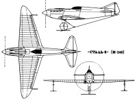
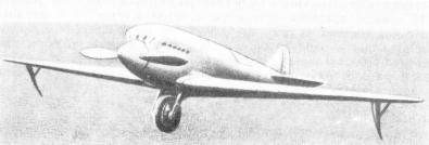
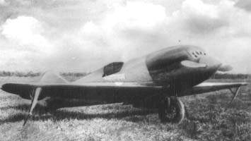
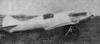
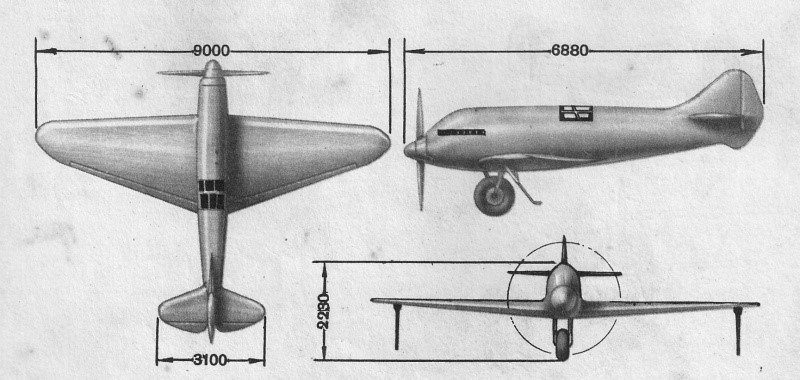
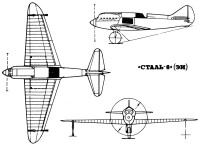
The Stal-8 (In Russian: Бартини Сталь-8) (I-240 in the VVS designation ) was a more practical development of the Stal-6 as a fighter.
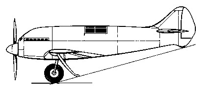
It was longer than its predecessor, by the use of a an M-100A (licence-built Hispano Suiza 12YBR) 860 hp engine and was characterized by the presence of a protruding cabin in the upper fuselage, to maintain aerodynamic cleanliness. Unlike the Stal-6 the pilot’s seat was fixed in its upper position.
The Stal-8 construction was mainly the aluminum-magnesium alloy Altmag. The joints were made by spot welding. The cooling system and landing system were very similar to those of the Stal-6. Two 7.62mm ShKAS machine-guns were to be fitted in the top decking over the engine, synchronised to fire through the propeller.
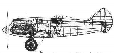
Structurally, the Stal-8 featured a monocoque fuselage formed from metal slats with a C-type profile. The wing was built around two spars with stamped steel ribs. Altmag’s wing coating, 0.5mm thick on the top and 0.8mm thick on the bottom.
The forward part of the wing included the evaporative cooling system. The ‘enerzh’ double skinned surface-evaporation radiators formed the leading edge skin, back to the main-spars. The 4-section ailerons were located on the trailing edge, which could be used as flaps during takeoff, landing and turns. Like the Stal-6, it maintained the system for varying the angle of incidence of the elevator rudders as a function of flight speed.
The 175-liter fuel capacity was achieved through two tanks located near the wing root. The oil tank upper part formed part of the surface of the fuselage in front of the cockpit. In this way, at high speeds, the oil was cooled by the air flow itself.
Construction of the Stal-8 was started in the ships of Factory No.240. Work on the prototype was suspended in late 1934, when work was at approximately 60%. The reasons were various, among them because the GVF, in whose institute Bartini’s brigade worked, was not very in favor of generating military devices in its facilities that did not contribute to their needs. On the other hand, the State Directorate for the Aeronautical Industry (GUAP) did not pay much attention to the project either, considering it “foreign” as it was a responsibility of the GVF. The new Polikarpov fighters I-15 and I-16s were being produced and although the Stal-8 was superior in many respects, there were great doubts about the vulnerability of the cooling system.
Stal-8 Engine: Mikulin M-100, 860 hp (licensed Hispano-Suiza Ybrs) Wingspan: 9.60 m Wing area: 15.30 m² Length: 8.22 m Height: 2.23 m Empty weight: 1100 kg Maximum takeoff weight: 1740 kg Fuel capacity: 250 kg Wing loading: 100 kg / m² Power load: 1.75 kg / hp Maximum speed at sea level: 550 km / h Maximum speed at 3000 m: 630 km / h ROC: 20 m / sec Practical range: 180 km Practical ceiling: 9500 m Endurance: 2.4 hours Range: 800 km Take-off run: 190 m Accommodation: 1
The work started by AI Putilov in the OOS of the NII GVF on the use of steel in aeronautical construction was followed by other groups of engineers. On April 30, 1930, Bartini proposed to the management of the Central Construction Bureau (TsKB) the creation of a fast airplane with a totally clean aerodynamically airframe. The project was analysed and approved, but its realization was very far away.
First of all, Roberto Bartini , despite being a communist, was Italian and therefore could not be allowed to have access to the secrets of the Soviet aeronautical industry. Second, most airplane builders at that time did not believe in the “wonderful foreign engineer” and therefore did not wish to share their experience with him.
Fortunately, help came from the VVS chief Pyotr Ivanovich Baranov and the RKKA chief of armaments Mikhail Nicolaevich Tukhachevsky. They succeeded in starting in 1932 the fast plane project works at the CNII (Factory No. 240).
The Stal-6 was originally conceived by Bartini as a fighter under the name EI ( Э кспериментальный И стребитель – Experimental Fighter). As it was developed within the structure of a civilian research institute, no weapons were installed.
Structurally, it was conceived as a low-wing single-seater monoplane, with a wing area of 14.3 sq.m. The tail unit was of the monoplane type. One of the most unusual features of the new aircraft was the presence of a single 800 x 200 mm wheel on the front centre portion of the fuselage with two stabilization skis on the underside of the wings. Both the wheel and the skis were fully retractable. The retraction system was manual using a rope system.
The structure was made of chromium – moly steel tubes (hence the name Stal – Steel) and the skin was an aluminum-magnesium alloy (AltMag, Electron) on the entire front and Bakelite on the tail. The wings featured a steel tube structure with a stainless-steel coating. The wing ribs were made of U-type steel profiles. The fuselage was noted for its aerodynamic cleanliness with the cockpit deck flush with the top of the fuselage. The weight of the aircraft with the 660 hp engine was only 850 kg.
Stal-6 structural drawing
The aircraft used an evaporative water-cooling system inside the wings. The engine’s cooling water was heated to steam. The steam was circulated through the double wing cladding made of ‘enerzh-6’ (stainless) steel. There it condensed to become a liquid state again and cooled to return to the engine. This configuration avoided the use of external radiators, improving the aerodynamics.
The control of the elevators could be adjusted so that the pilot could vary the pressure to exert on the control stick depending on the flight regime and speed.
To minimize air resistance, the cockpit was inserted into the fuselage, without protruding. Visibility of the runway during takeoff and landing operations was ensured by moving the pilot’s seat upward, with the pilot’s head protruding above the level of the fuselage. During the flight the seat was returned to its normal position.
In 1933, under the direction of Bartini, the construction of the single-seat Stal-6 (Russian Сталь-6) began.
The first flights began on October 7, 1933. In one of the first flights 400 km / h were reached. Pilots A.B.Yumashiev and P.M.Stefanovsky demonstrated that take-off and landing operations with a single centre wheel were as safe and easy as with conventional gear.
The speed reached at sea level was 420 km / h, almost 100 km / h higher than that of contemporary fighters and was a new world speed mark for aircraft in its class. It is noteworthy that the main RKKA fighter at the time was the Polikarpov I-5 that reached only 280 km / h and the new fighter also devised by Nikolai Polikarpov that was preparing to be tested at that time, the I-16 with an M-22 engine, only reached 359 km / h.
The reaction that the Stal-6 provoked was not what was expected. VVS authorities immediately ordered its builders to work on increasing the speed of their fighters. The builders began to protest, claiming that increases in speed were impossible to achieve in such a short time. The GVF (Civil Aviation Fleet) was ordered to build a fighter based on the Stal-6. This fighter was named Stal-8.
Important discussions centred on the vulnerability of the use of the vaporization cooling system. All water-cooled systems are generally more vulnerable than air-cooled systems, unless they are specially armored as in the Ilyushin Il-2. However, the increased area of the cooling surface in the vaporization system, which increases the risk of impact, is offset by the less impact of a hole in the entire system.
During the Stal-6 flight tests, the pilot ABYumashiev carried out several flights with the cooling system switched off to mimic damage to the cooling system. Each flight lasted more than 30 minutes. Taking into account that the autonomy of the majority of Soviet fighters of the time did not exceed one hour, it follows that the damaged fighter could not only return to its base satisfactorily, but could also finish its combat without problems. The Stal-6 used a single cooling unit and this could have been a development point as well, as segmented systems tend to be less vulnerable.
Engine: 1 × V-1570 Curtiss Conqueror, 469.8 kW (630 hp) Wingspan: 9.0 m (29 ft in) Wing area: 14.3 sq.m (154 sq.ft) Length: 6.88 m (22 ft 6-3/4 in) Height: 7.316 ft / 2.23 m Empty weight: 850 kg (1,874 lb) Gross weight: 1,080 kg (2,381 lb) Fuel capacity: 135 kg Maximum speed at height: 420 km/h (261 mph) Maximum speed at sea level: 350 km / h Landing speed: 110 km / h Ceiling: 8000 m Rate of climb: 21 m/s (4,135 ft/min) Climb to 1000m: 0.8min Climb to 2000m: 2.0min Climb to 3000m: 3.0min Endurance: 1.5 hours Practical range: 180 km Take-off run: 150 m in 10 seconds Landing roll: 280 m in 20 seconds Crew: 1
Bartini, Robert Ludvigovich (Roberto Oros di Bartini) (1897-1974) Robert Bartini, in 1915, graduated from gymnasium, was drafted and sent to school of officers’ reserve located in the town of Banská Bystrica (today’s Slovakia). Upon graduation in 1916, Bartini was sent to Russian-Austrian-Hungarian front where he was captured in June 1916, flying school in 1921 and Politecnico di Milano in 1922. Bartini became a member of the Italian Communist Party in 1921. After the Fascist takeover in Italy in 1923, he was transferred undercover to the USSR as an aviation engineer. He occupied several engineering and command positions in the Soviet Air Force and RKKA. He became the head of the department of amphibious experimental aircraft design in 1928. He was the head of the design department of NII GVF, general designer (chief designer), since 1930. He was imprisoned from 1938 to 1946. He continued his work on new aircraft designs as a prisoner in TsKB 29 NKVD and in OKB-86 on the territory of Dimitrov Aircraft Factory and Beriev Aircraft Company in Taganrog (1946–1952), then in SibNIA, Novosibirsk. R.L.Bartini was rehabilitated in 1956. He also published papers concerning aviation construction materials and technology, aerodynamics, dynamics of flight, and even theoretical physics.
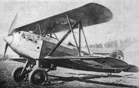
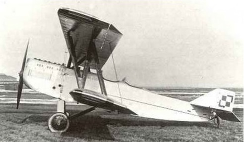
The aircraft was designed by Ryszard Bartel in the Samolot factory in Poznań, as a trainer-fighter plane. A mixed construction biplane. Steel framed fuselage, rectangular in cross-section, canvas covered (engine and upper sections – aluminum covered). Rectangular two-spar wings with rounded ends, plywood and canvas covered. Upper wing span: 7.36 m, lower wing span: 8.10 m. Lower and upper wing halves were interchangeable. Single pilot, sitting in open cockpit, with a windshield. The V8 engine Hispano-Suiza 8Be was modified to lower power output (from 220 hp to 180 hp). Radiator below the fuselage. Fixed landing gear, with a rear skid.
The BM-6 prototype, designated BM-6a, was flown on 8 April 1930 in Poznań. Its advantage was an easy construction and maintenance, according to Bartel’s design philosophy. A distinguishing feature of all Bartels was an upper wing of a shorter span, because lower and upper wing halves were interchangeable (i.e. the lower wingspan included the fuselage width). It first introduced a mixed construction to Bartel’s designs.
After trials, the prototype was modified in July 1930. The prototype was later redesignated BM.6a/II after it was substantially modified. It offered quite good flight characteristics and was capable of aerobatic flight. It was demonstrated in a fighter-plane competition in Bucharest in 1930, along with the similar PZL P.1.
BM-6a2
The second prototype BM-6b, with a Wright Whirlwind 220 hp radial engine, was ordered, but work upon it ceased with closure of the Samolot factory in mid-1930. The PWS works, which inherited many of Samolot’s projects, did not continue the project, for it had its own similar design, the PWS-11.
After state trials in 1931, the prototype was used in an advanced training school in Grudziądz, then in an aviation training center in Dęblin.
BM-6a Engine: 1 × Hispano-Suiza 8Be (modified), 180 hp Propeller: Two-blade wooden fixed pitch Wingspan: 8.10 m Wing area: 17.6 m² Length: 6.30 m Height: 2.76 m Empty weight: 697 kg Loaded weight: 985 kg Fuel capacity (fuselage): 168 lt Useful load: 288 kg Wing loading: 56 kg/m² Maximum speed: 192 km/h Cruise speed: 165 km/h Stall speed: 85 km/h Range: 550 km Service ceiling: 3,800 m Rate of climb: 4 m/s Armament: One synchronised 7.7 mm Vickers machine gun in fuselage Crew: 1
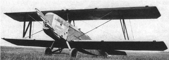
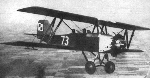
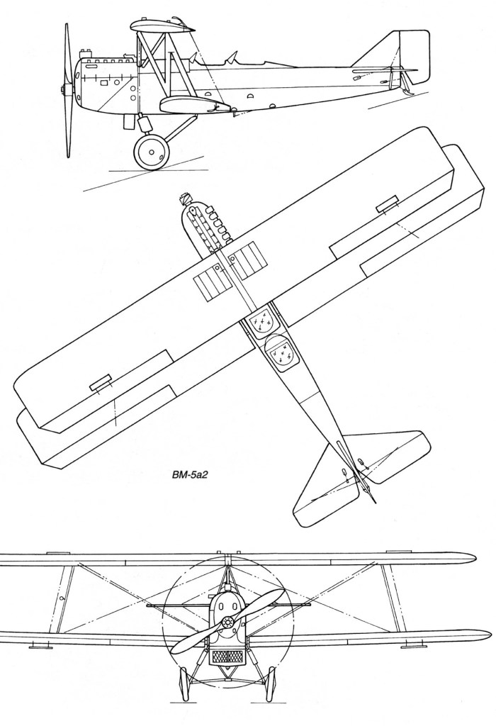
The Bartel BM-5 was designed by Ryszard Bartel with Z. Nowakowski , J. Medwecki , S. Nowkuński in the Samolot factory in Poznań, as an advanced trainer, transitory between primary trainers and bomber or reconnaissance aircraft.
A further development of the Bartel BM-3, it was a wooden construction biplane, the fuselage was rectangular in cross-section, plywood covered (engine section – aluminum covered). Rectangular two-spar wings, plywood and canvas covered. Crew of two, sitting in tandem in open cockpits, with individual windshields and twin controls, instructor in rear cockpit. Fixed landing gear, with a rear skid. Engine in front, with a water radiator below fuselage nose (BM-4a,b,c). Two-blade wooden propeller. Fuel tanks in upper wings and fuselage, capacity: 235-270 t.
BM-5a1
The upper panels were identical to the bottom and braced with N steel pipe and wood double links. Upper panels attached to the hull placed on the pyramid of 6 steel pipes and wood. Ailerons on all wings, covered with plywood. The fuselage of rectangular cross-section rounded at the top, was covered with plywood. The front part of the fuselage covered with removable end caps made of aluminum sheet. Trapezoidal tail welded steel pipe, covered with canvas. Tail horizontal casement, supported by struts with steel pipes, vertical tail stiffened profiled of tube.
The BM-5 prototype construction started in March 1928 and flown on 27 July that year in Poznań. It had good handling, high stability and spin resistance, which made it a suitable trainer for larger aircraft. The plane was transferred to the military trials, during which some changes were made. During the evaluation flights at the Ławica airport during winter 1929, skis were installed on the aircraft, which proved suitable. A distinguishing feature of all Bartels was an upper wing of a shorter span, because lower and upper wing halves were interchangeable (i.e. the lower wingspan included the width of the fuselage).
BM-5a1
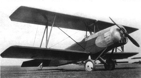
The first prototype was designated BM-5a1 and was fitted with a 220 hp (160 kW) Austro-Daimler inline engine. The second prototype, flown on 15 April 1929, was designated BM-5b1 and was fitted with a 230 hp (170 kW) SPA-6A inline engine. Compared with its predecessor, it was heavier by 60 kg due to a larger supply of fuel. Two BM-5b1 were built. It was refitted in August with a 320 hp (240 kW) Hispano-Suiza 8Fb V-engine and redesignated BM-5c1 (it was meant to utilize engine stores from the Bristol F.2 Fighter) and was flight tested on July 29, 1929. Next 20 aircraft of each type were built: BM-5a2, BM-5b2 and BM-5c2.
Bartel BM-5b
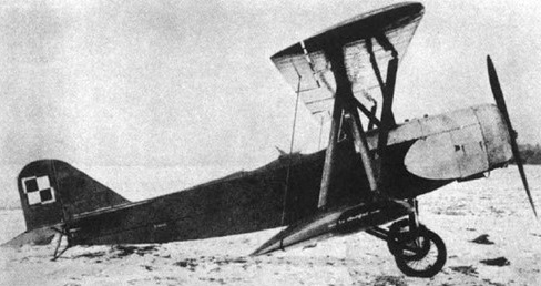
A disadvantage of most BM-5s were old and faulty engines. From all the variants the BM-5a variant was the heaviest and had the worst performance. Several BM-5a burned in a fire in September 1929. For that reason in 1935 one BM-5 was fitted at the PZL works with a 240 hp (180 kW) Wright Whirlwind J-5 radial engine, produced in Poland (in Polish Skoda Works, then Avia). This variant was designated the BM-5d and 20 of BM-5a and BM-5b were next converted to BM-5d.
BM-5d
On March 20, 1929 a contract was signed for series production of 40: 20 version of the VM-5a and 20 versions of BM-5b, with the first five were equipped with AD225 engine, and the next five – SPA. All production aircraft received the military designation BM-5R2 and deliveries were completed in 1930. These aircraft are sometimes called BM-300. Single copies were in training regiments, squadrons and air camps.
BM-5c1
A total of 62 were built.
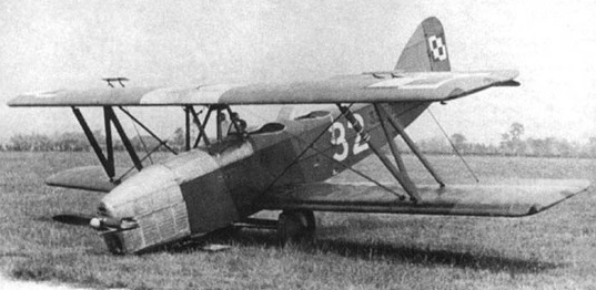
BM-5s were used in the Polish Air Force for training from 1930, in a central pilots’ school in Dęblin. 5 BM-5c’s were used in Naval Air Unit (MDLot) in Puck. Most were written off in the second half of 1930s and replaced with the PWS-26 in April 1938. Some survived until the German invasion of Poland in September 1939. None survived the war.
BM-5c2
Variants:
BM-5a Austro-Daimler 6-cylinder straight engine, water-cooled, 220 hp (160 kW) nominal power Wingspan: 11.2 m Length: 7.81 m Height: 3.18 m Wing area: 31.0 m2. Empty weight: 980-972 kg Useful load: 370-432 kg MTOW: 1350-1395 kg Max speed of 164 kph Cruise: 145 kph Stall: 76-80 kph ROC: 2.6 m / s Ceiling: 3250 m Range: 420-550 km
BM-5a2 Engine: Austro Daimler, 225 hp Wingspan: 11.20 m Length: 7.81 m Height: 3.18 m Wing area: 31.00 sq.m Empty weight: 980 kg Normal takeoff weight: 1350 kg Maximum speed SL: 164 km / h Cruising speed: 145 km / h Practical range: 420 km Rate of climb: 156 m / min Ceiling: 3250 m Crew: 2
BM-5b SPA-6A 6-cylinder straight engine, water-cooled, 230 hp (170 kW) take-off power, 220 hp (160 kW) nominal power Wingspan: 11.2 m Length: 7.81 m Height: 3.18 m Wing area: 31.0 m2 Empty weight: 922-906 kg Useful load: 378 kg MTOW: 1300 kg Max speed: 161 kph Cruise: 145 kph Stall: 70 kph ROC: 3.4 m / s Ceiling: 3075 m Range: 435 km
BM-5c Hispano-Suiza 8Fb 8-cylinder V-engine, water-cooled, 320 hp (240 kW) take-off power, 300 hp (220 kW) nominal power Wingspan: 11.2 m Length: 7.81 m Height: 3.18 m Wing area: 31.0 m2 Empty weight: 947 kg, 383 kg MTOW: 1330 kg Max speed: 172 kph Cruise: 150 kph Stall: 73 kph ROC: 4.5 m / s Ceiling: 4750 m Range: 300-360 km
BM-5d Wright Whirlwind J-5 9-cylinder radial engine, 240 hp (180 kW) take-off power, 220 hp (160 kW) nominal power Wingspan: 11.2 m (36 ft 9 in) Wing area: 31 m² (334 ft²) Length: 7.6 m (24 ft 11 in) Height: 3.18 m (10 ft 5 in) Empty weight: 900 kg (1,980 lb) Loaded weight: 1,290 kg (2,838 lb) Useful load: 390 kg (858 lb) Wing loading: 41.6 kg/m² (8.50 lb/ft²) Power/mass: 140 W/kg (0.085 hp/lb) Maximum speed: 172 km/h (93 knots, 107 mph) Cruise speed: 150 km/h (81 knots, 93 mph) Stall speed: 70 km/h (38 knots, 43 mph) Range: 450 km (243 nm, 280 miles) Service ceiling: 4,000 m (13,100 ft) Rate of climb: 4 m/s (790 ft/s) Crew: 2, student and instructor Armament: None
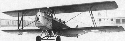
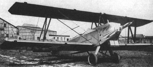
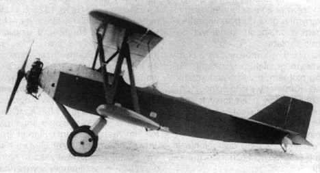
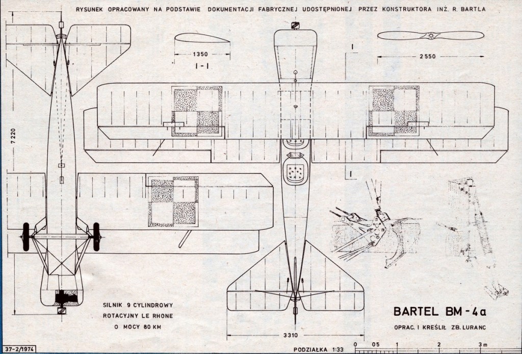
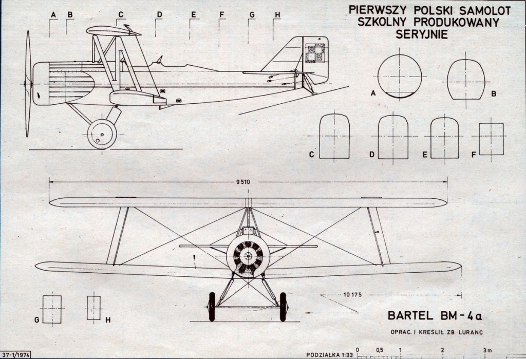
The aircraft was designed by Ryszard Bartel in the Samolot factory in Poznań. It was a development of the Bartel BM-2, which did not advance beyond the prototype stage. The Bartel BM-4 performance was superior to the BM-2, and also to the Hanriot H.28, used by the Poles and licence-built by Samolot.
Wooden construction biplane, conventional in layout. Fuselage rectangular in cross-section, plywood covered (engine section – metal covered). Rectangular two-spar wings, plywood and canvas covered. Crew of two, sitting in tandem in open cockpits, with individual windshields. Cockpits with dual controls, instructor’s at rear. Fixed landing gear, with a rear skid.
The BM-4 prototype was flown on 20 December 1927 in Poznań. It had good handling and stability and was resistant to spinning. A distinguishing feature of all Bartels was an upper wing of a shorter span, because lower and upper wing halves were interchangeable (i.e. the lower wingspan included the width of the fuselage).
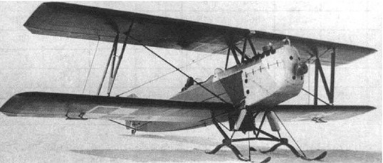
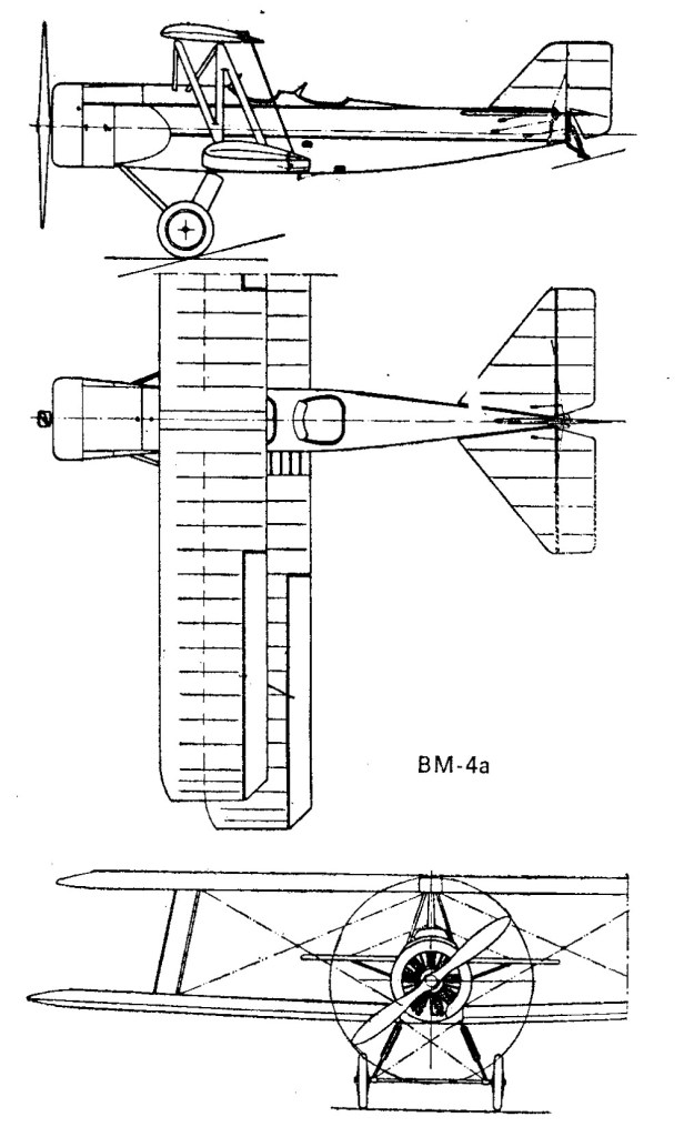
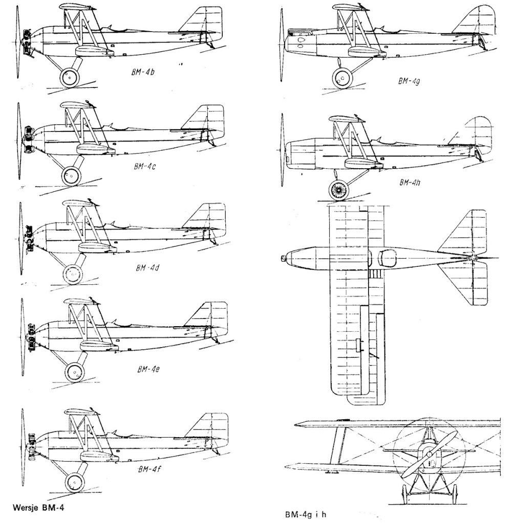
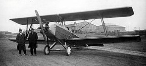
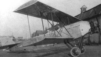
The first prototype was designated BM-4b and was fitted with 90 hp Walter Vega radial engine. The first prototype BM-4b was given to the king of Afghanistan Amanullah Khan during his visit to Poland in 1928. The second prototype, flown on 2 April 1928, was designated BM-4d and fitted with the Polish experimental 85 hp WZ-7 radial engine, then refitted with 80 hp Le Rhône 9C rotary engine and redesignated BM-4a. The BM-4a became a production variant, because the Polish Air Force had a store of Le Rhône engines. 22 aircraft were ordered and built in 1928–1929. This variant had a cowled engine which made it different from all other BM-4s with radial engines.
B-4all
Next several variants remained experimental. The BM-4c with a 125 hp Lorraine-Dietrich 5Pb radial engine, built as a one-off in 1928, was supposed to be used for long-distance flights to advertise the engines, but was finally used as the factory’s aircraft. Three BM-4a’s were converted to BM-4e of 1930 with the Polish experimental 85 hp Peterlot radial engine, the BM-4f of 1931 with the Polish experimental 120 hp Skoda G-594 Czarny Piotruś radial engine, and the BM-4g of 1931 with 100 hp de Havilland Gipsy I inline engine. The last one competed against the RWD-8 in a search for a standard trainer aircraft, but was not selected. After tests in 1932, all three were converted back with Le Rhône engines.
BM-4h
The second series variant became BM-4h, with 120 hp de Havilland Gipsy III or 120 hp Walter Junior 4 inline engines. Like late BM-4a’s, they had a rounded tailfin and a modified undercarriage. Due to the Samolot factory’s closure in 1930, the BM-4h was developed at the PWS (Podlaska Wytwórnia Samolotów) and built there in 1932 in a series of about 50 aircraft.
BM-4b
BM-4a’s were used in the Polish Air Force from 1929 – in pilots’ school in Bydgoszcz. 6 burnt in September 1929 in the Samolot factory. BM-4h’s were used in the Polish Air Force from 1932, in schools in Bydgoszcz and Dęblin. They only partly replaced Hanriot H.28s and were themselves replaced with the RWD-8. They had military numbers starting with 33.
In 1936 the Polish Air Force handed over their remaining 23 BM-4h’s to civilian aviation – most to regional aero clubs, some to the Ministry of Communication. They received registrations SP-BBP – BBZ and from a range SP-ARB to ARZ. Several survived until the German invasion of Poland in September 1939. Several were used as liaison aircraft during the campaign. None survived the war.
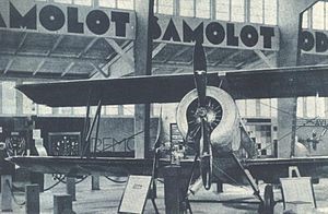
BM-4 at exhibition in Poznan, 1929
Variants:
BM-4a Engine: Le Rhône 9C, 80 hp / 60 kW nominal power. Propeller: Two-blade wooden 2.55 m diameter. Wingspan: 10.175 m (33 ft 5 in) Wing area: 25 m2 (270 sq ft) Length: 7.22 m (23 ft 8 in) Height: 2.93 m (9 ft 7 in) Empty weight: 538 kg (1,186 lb) Gross weight: 359 kg (791 lb) Fuel tank (fuselage): 89.5 lt Wing loading: 31.6 kg/m2 (6.5 lb/sq ft) Power/mass: 0.101 kW/kg (0.0615 hp/lb) Maximum speed: 125 km/h (78 mph; 67 kn) at sea level Cruising speed: 110 km/h (68 mph; 59 kn) Stall speed: 57 km/h (35 mph; 31 kn) Endurance: 3 hours Service ceiling: 2,820 m (9,252 ft) Rate of climb: 1.9 m/s (370 ft/min) Time to altitude 1,000 m / 3,281 ft: 9 min 42 sec Crew: 2
BM-4b Engine: Walter Vega, 90 hp take-off power, 85 hp nominal power. Propeller: Two-blade wooden 2.55 m diameter. Fuel tank (fuselage): 89.5 lt
BM-4c Engine: Lorraine-Dietrich 5Pb, 125 hp take-off power, 110 hp nominal power. Propeller: Two-blade wooden 2.55 m diameter. Fuel tank (fuselage): 89.5 lt
BM-4d Engine: Avia WZ-7, 85 hp take-off power, 80 hp nominal power. Propeller: Two-blade wooden 2.55 m diameter. Fuel tank (fuselage): 89.5 lt
BM-4e Engine: Peterlot, 85 hp take-off power, 80 hp nominal power. Propeller: Two-blade wooden 2.55 m diameter. Fuel tank (fuselage): 89.5 lt
BM-4f Engine: Skoda G-594 Czarny Piotruś, 120 hp take-off power, 100 hp nominal power. Propeller: Two-blade wooden 2.55 m diameter. Fuel tank (fuselage): 89.5 lt
BM-4g Engine: de Havilland Gipsy I, 100 hp take-off power, 90 hp nominal power. Propeller: Two-blade wooden 2.55 m diameter. Fuel tank (fuselage): 89.5 lt
BM-4h Engine: de Havilland Gipsy III, 120 hp nominal power or Walter Junior 4, 120 hp take-off power, 110 hp nominal power. Propeller: Two-blade wooden 2.55 m diameter. Fuel tank (fuselage): 89.5 lt
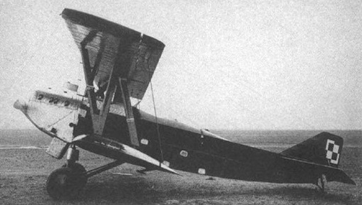
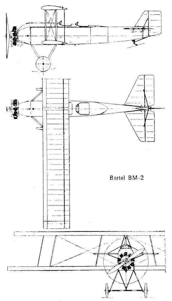
The Bartel BM-2 was designed by Ryszard Bartel, a chief designer of Samolot factory in Poznań. It was the first Polish design of a trainer plane. Initially it was known as Bartel M-2, then BM-2 (M was for designer’s wife Maryla).
A wooden construction biplane, conventional in layout. Fuselage rectangular in cross-section, plywood-covered (engine section – metal covered). Rectangular two-spar wings, plywood- and canvas-covered. Crew of two, sitting in tandem in open cockpits, with individual windshields. Cockpits with twin controls, the instructor seated aft. Fixed landing gear, with a rear skid (main gear with a common axle, sprung with a rubber rope). Radial engine in the fuselage nose, without a cowling.
A feature of the BM-2 and all Bartels was an upper wing of a shorter span, because the lower and upper wing halves were interchangeable (i.e. the lower wingspan included the width of the fuselage). Also Bartel put a stress on standardizing the construction materials used: steel pipes, metal sheet etc, in order to make production and repairs easier. A distinguishing feature of the BM-2 was the upper wing directly over the lower wing – un-staggered wings, while in later Bartel designs, the wings incorporate forward stagger.
The prototype was flown on 7 December 1926 in Poznań. In June 1927 it was shown at the first Aviation Exhibition in Warsaw. It was tested in 1927 and evaluated as quite good, but it was not built in series, because Bartel decided to design an improved aircraft, which resulted in the Bartel BM-4 trainer, which was produced in quantity. After flight testing, the prototype was removed from service.
Engine: 1 × Salmson 9 Ac, 90 kW (120 hp) Prop: 2 blade, 2.24m diameter Wingspan: 11.77 m (38 ft 7¼ in) Wing area: 28.6 m² (308 ft²) Length: 7.8 m (25 ft 7 in) Height: 3.08 m (10 ft 1¼in) Empty weight: 695 kg (1,529 lb) Loaded weight: 970 kg (2,314 lb) Useful load: 275 kg (605 lb) Fuel capacity: 201 lt Cruise fuel consumption: 34 lt/hr Maximum speed: 128 km/h (69 knots, 80 mph) Cruise speed: 100 km/h (54 knots, 62 mph) Stall speed: 65 km/h (35 knots, 40 mph) Range: 320 km (173 nm, 199 miles) Service ceiling: 4,000 m (8,800 ft) Rate of climb: 2.9 m/s (570 ft/min) Wing loading: 33.8 kg/m² (7.51 lb/ft²) Power/mass: 0.093 kW/kg (0.052 hp/lb) Crew: 2, student and instructor