The Chevrolair was not – as is often claimed – a car engine adapted for aviation use. It was a purpose-designed aero-engine by the Chevrolet Brothers Aircraft Company. This engine was designed and Chevrolet Brothers
Around 1925 Louis Chevrolet started taking a deeper interest in aviation, attending air shows in and around the Indianapolis area. In 1926 he entered into negotiations with a group of Ohio businessmen who were looking to develop a new airplane engine. In the spring of 1927, the Chevrolet brothers completed their first aviation engine, an air-cooled, single-overhead-cam, 4-cylinder engine. This engine was installed in a biplane built by the Moundsville Aircraft Corp of West Virginia. There are photos of Charles Lindbergh inspecting the engine in that airplane in the summer of 1927. On the plane’s maiden flight, it was forced to make an emergency landing because of engine trouble (thankfully nobody was hurt). The Chevrolet brothers went back to the drawing board, and news of their venture quickly disappeared from the public eye. In late 1927 or early 1928 the brothers had a heated argument, split up, and did not talk to each other for several years to follow. Given the failure of the first aero engine, and the events that took place in early 1928, it would appear that the argument stemmed from the design of their airplane engine.
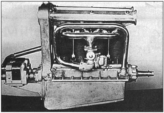
In the spring of 1928, Louis left the Chevrolet Brothers Manufacturing Company and started a new company called the Chevrolet Aircraft Corporation. Louis then spent the next year developing his new engine with Charles Merz (veteran of the 1st Indy 500). Arthur continued working on the old airplane engine, modifying the design, and photos from September 1928 show a similar style engine but with a double overhead cam set up.
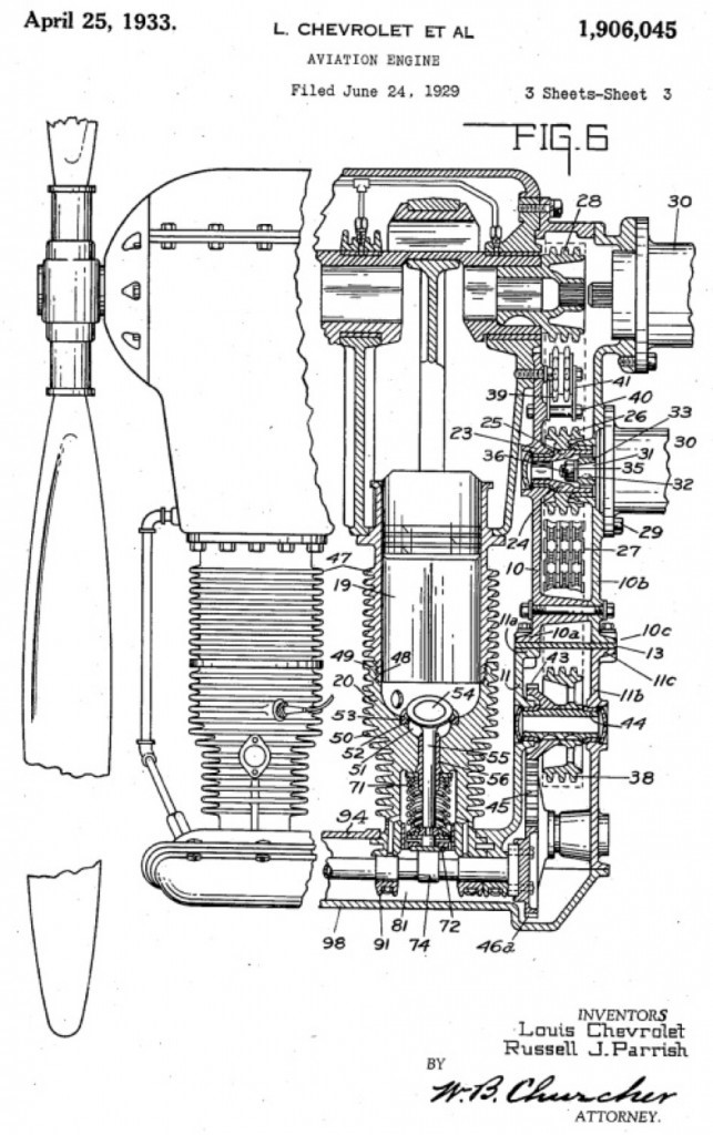
Louie’s new airplane engine was an inverted design with the crankshaft on top, and the cylinder heads and valve train components on the bottom of the assembly. Louis then sought out new investors to take his idea from paper into production.
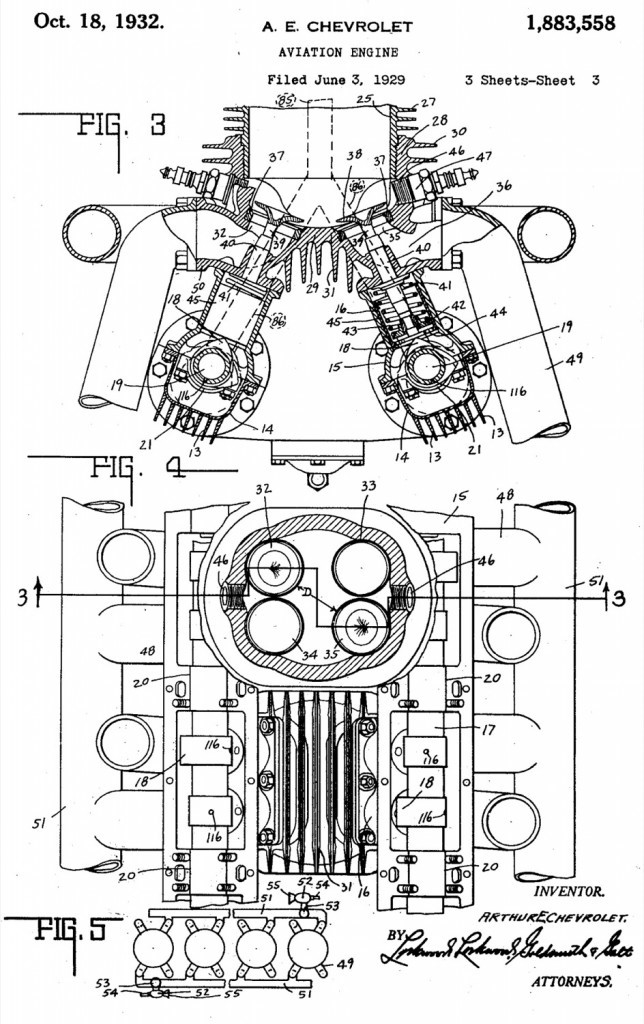
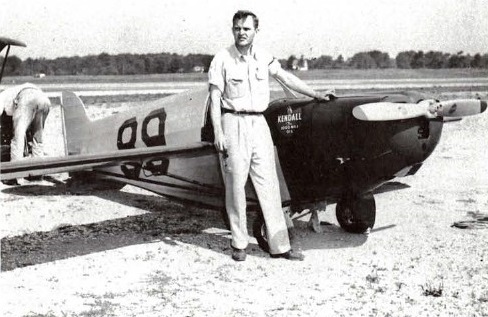
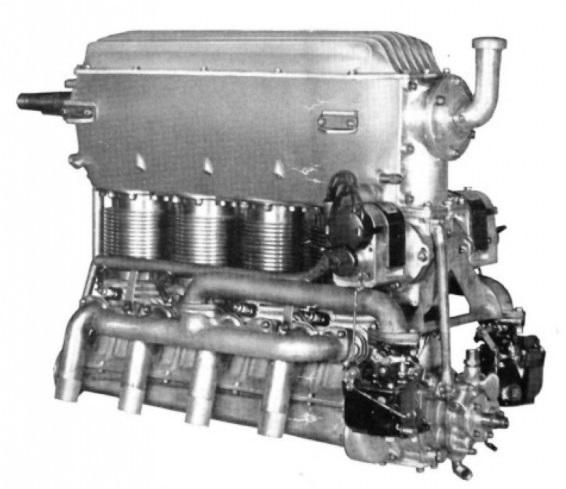
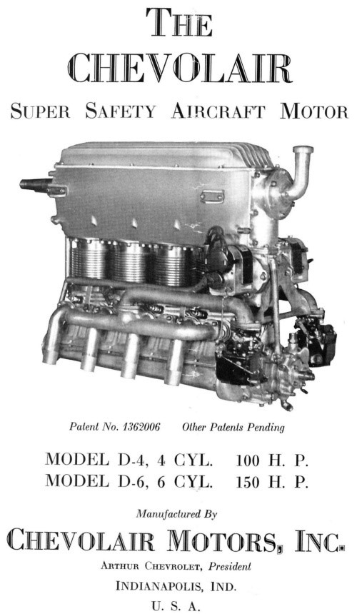
Art’s modified engine design apparently wasn’t successful, and he then designed a completely new engine in the spring of 1929 called the Chevolair. The Chevolair was an inverted engine, using four valves per cylinder, with intake and exhaust valves staggered on each side of the cylinder head. The staggered valve pattern necessitated the use of intake and exhaust manifolds on each side of the engine. Art built both a 4-cylinder and a 6-cylinder engine in the summer of 1929. The 6-cylinder was tested by the Bureau of Aeronautics, and it received Approved Type Certificate No. 56 in July 1930. This same 6-cylinder engine was used by Walter Beech in the Travel Air Mystery Ship for the 1929 National Air Races, but it did not perform very well. A 4-cylinder Chevolair engine was used in a Travel Air biplane for some time. A couple of other planes used the Chevolair engine including a Laird Aircraft, and a Robin Aircraft. Art’s company lost traction after the stock market crash of 1929, and went into receivership in 1932. Very few Chevolair engines were made, and none are accounted for today.
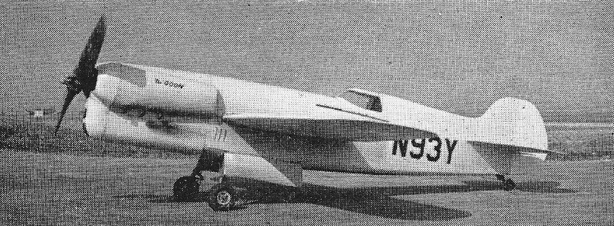
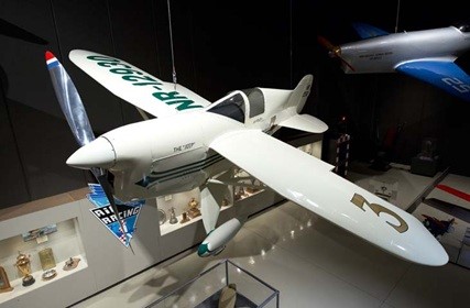
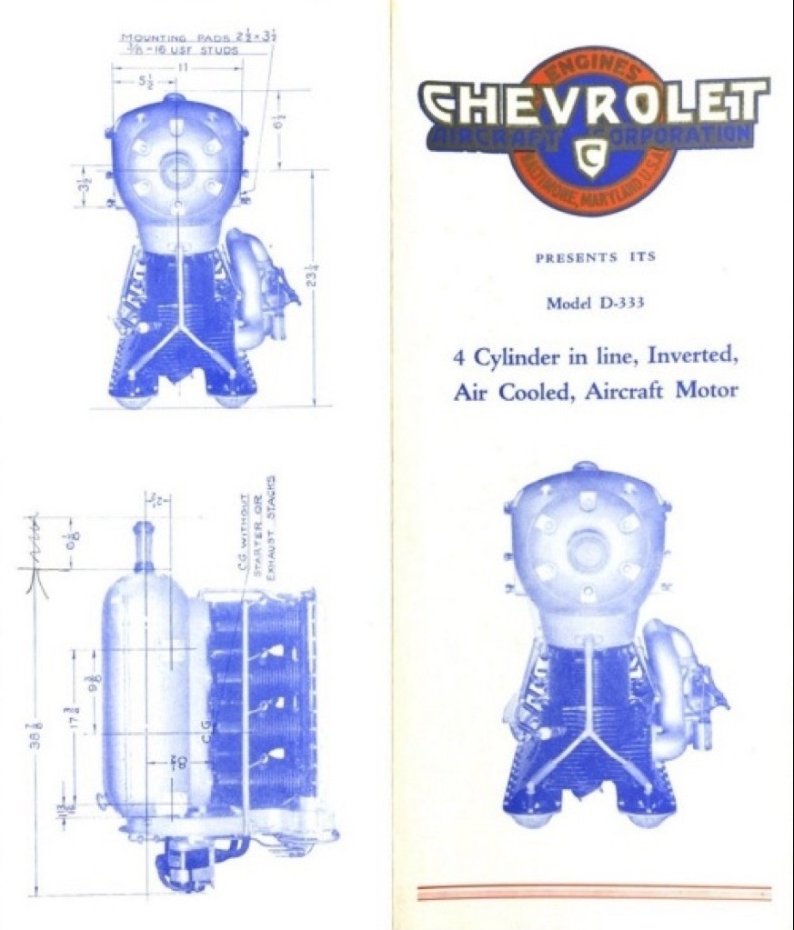
Designated Model D-4, the engine was certificated in December 1929, and became known as the Chevrolair. A D-4 engine powered Travel Air low-wing aircraft won first place in its class at the September 1930 Cleveland National Air Races.
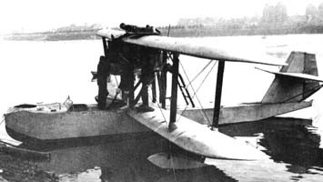
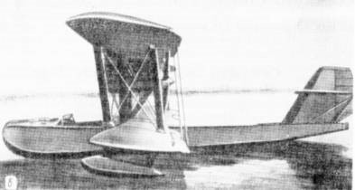
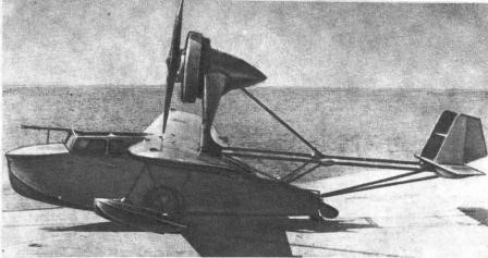
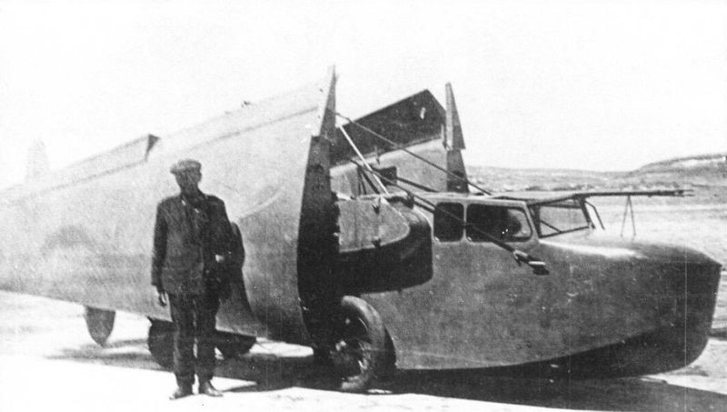
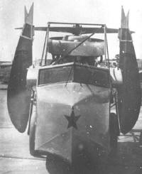
The D-333 4-cylinder engine was installed in an interesting variety of aircraft, including biplane, monoplane, seaplane, and even an autogiro. Additionally, there is correspondence in the War Department files that Louis’s engine was being considered for use in the TC-14 blimp project.
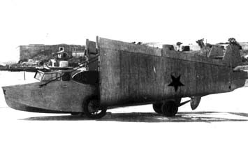
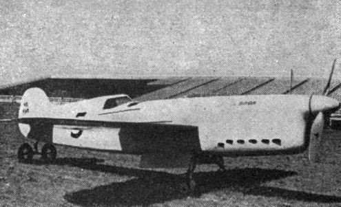
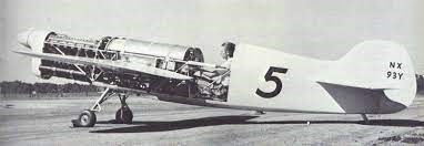
A few airplanes that used Louis’ engine have survived. A Waco ENF is still around, and it was the original test mule for Louis’ engine. A Granville Brothers “Gee Bee Model A” biplane is now in Oregon, and it once had a Chevrolet engine in it. Finally a Martin seaplane has been restored, and is hanging in the Baltimore Museum of Industry (it is the only known aircraft that retains a Chevrolet engine).
Subsequently, the Chevrolet Brothers Aircraft Company failed and the engine design sold to the Glenn L. Martin Company of Baltimore, Maryland. Uprated and renamed Martin 333, it was recertificated in July 1930, and powered the Martin 162A Tadpole Clipper and various Driggs aircraft.
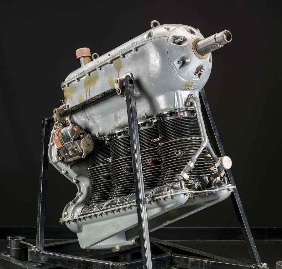
Type: Reciprocating, In-line, Inverted, 4 cylinders, Air-cooled
Power: 89.5 kW (120 hp) at 2,100 rpm
Displacement: 5.47 L (333.98 cu in.)
Bore and Stroke: 114 mm (4.5 in.) x 133 mm (5.25 in.)
Weight: 120 kg (265 lb)
Length 116. 2 cm (45.75 in.),
Width 45.09 cm (17.75 in.),
Height 87.00 cm (34.25 in.)
Aluminum, Steel, Paint, Phenolic, Rubber, Magnesium