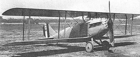
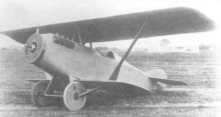
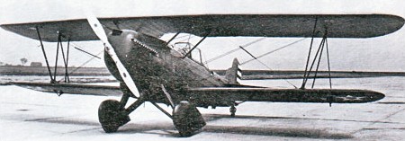
US Army interest in the 18-T prompted Curtiss to offer the same basic design in two-bay biplane configuration, and an order was placed by the US Army for two examples in August 1918. Known unofficially as the “Hornet”, the 18-B two-seat fighter employed an identical fuselage to that of the 18-T and a similar Curtiss- Kirkham K-12 engine. The proposed armament comprised two forward-firing Marlin guns and two Lewis guns on a flexible mount. The two prototypes were delivered to the US Army during the summer of 1919, AS40058 and AS40064, one being confined to static testing and the other crashing shortly after the commencement of flight trials. Further development was then abandoned.
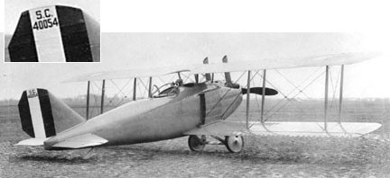
Photo above clearly shows a tail number of “40054,” but all recorded registrations have that number as the 18T triplane.
Engine: Kirkham K-12, 400hp Wingspan: 11.41 m / 37 ft 5 in Length: 7.11 m / 23 ft 4 in Wing area: 28.43 sq.m / 306.02 sq ft Take-off weight: 1300 kg / 2866 lb Empty weight: 767 kg / 1691 lb Useful load: 1177 lb Max. speed: 257 km/h / 160 mph Seats: 2
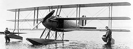
Designed by Charles B Kirkham, the Curtiss 18-T two-seat fighter triplane was ordered by the US Navy on 30 March 1918 when a contract was placed for two prototypes. The first (AS40065) was flown on 7 May 1918. Designed around the Curtiss-Kirkham K-12 water-cooled 12-cylinder engine of 350 hp and four-blade prop, the 18-T was a clean aerodynamic design by contemporary standards and featured a monocoque three-ply fuselage and side radiators positioned between the lower wings. The proposed armament was two forward-firing synchronized 7.62mm Marlin machine guns and two 7.62mm Lewis guns on a Scarff mounting in the rear cockpit.
The 18-T initially suffered some tail heaviness which was corrected by applying five degrees of sweepback to the wings for further trials. A max speed of 262km/h was achieved with full military load in August 1918, the 18-T being acclaimed as the world’s fastest aeroplane as a result.
Curtiss 18-T-1 A-3325
The US Navy promptly ordered two examples, the first (A3325) of which was delivered in February 1919 with a single float undercarriage.
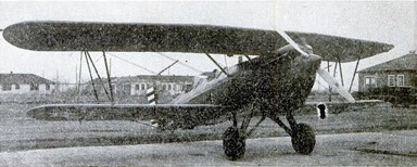
In the summer of 1919, the first Army prototype (AS40054) was fitted with longer-span two-bay wings, these having a span and area of 12.38m and 37.16sq.m respectively and 5° of sweepback were added, and in this form the aircraft became the 18T-2 (A3326), the short-span version becoming the 18T-1 (AS40059). The 18T-2 established a world altitude record of 34,610 ft / 10640m on 18 September 1919 (pilot Roland Rohlfs), and a second 18T-2 was built by Curtiss for export to Bolivia, where it arrived in 1920.
Curtiss 18-T-2 Rohlf’s altitude setter A-3326
Both Navy ships, used as land racers, crashed at the 1923 NARs.
18T-1 Engine: Curtiss-Kirkham K-12, 350 hp Wingspan: 9.70 m / 31 ft 10 in Length: 7.11 m / 23 ft 4 in Height: 3.02 m / 9 ft 11 in Wing area: 26.76 sq.m / 288.04 sq ft Take-off weight: 1383 kg / 3049 lb Empty weight: 898 kg / 1980 lb Max. speed: 265 km/h / 165 mph Cruise speed: 145 mph Stall: 58 mph Ceiling: 22,000 ft Seats: 2
18T-2 Engine: Curtiss D-12, 400hp Wingspan: 40 ft 7 in Length: 28 ft 3 in Speed: 139 mph Ceiling: 21,000 ft
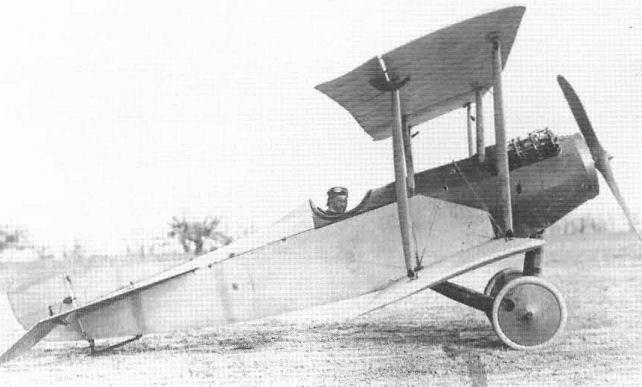
The Model S was Curtiss’ first attempt at a fast and manoeuvrable single-seat fighter. The first variant, S-1 Speed Scout, also called Baby Scout, had disappointing performance. The first Model S of 1916 was a single-seater built to the concepts of what European builders had called a Scout in 1914. This was a single-seat tractor biplane originally used for the work its name implied – the scouting of enemy activity.
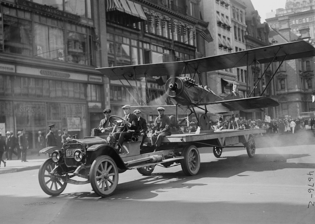
The sole Curtiss S-1 mounted on a truck for an Independence Day parade in New York City
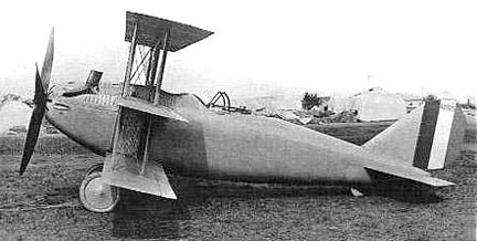
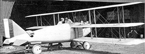
The original Model S-1 was the smallest aeroplane that Curtiss could build around the 90 hp OX engine. Construction was thoroughly conventional for the time, but the 20-ft (6,09 m) span of the single-bay wings was inadequate. The upper wing was lengthened and the strut arrangement was altered to two spanwise Vs. The S-1 did not sell, and Curtiss kept the modified prototype for its own use.
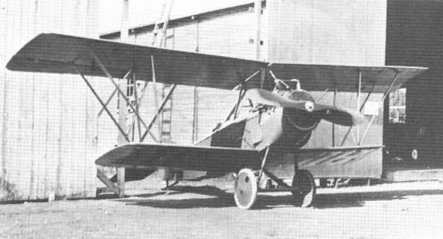
Model S-1 with the upper span increased and braced with diagonal struts
In March 1917, new wings were attached to the S-1 fuselage and a strut arrangement that eliminated the need for wing bracing wires, hence the name Wireless, and the project was redesignated S-2.
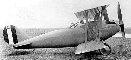
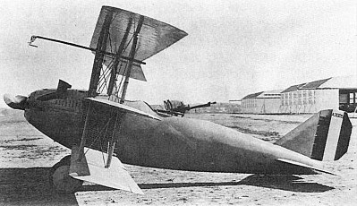
S-2 Wireless – The S-2 was essentially the Model S-1 fitted with new wings and a strut arrangement that eliminated the need for wing bracing wires, hence the name Wireless. The problem of fining shock absorbers in the undercarriage when the wing struts were anchored to the ends of the cross-axle was solved by using the new Ackermann Spring wheels, which featured curved spokes made of flat spring steel that served that purpose; these wheels did not have good resistance to side loads, unfortunately, and were not widely used. First flown in the summer of 1916 and demonstrated to the press by Curtiss pilot Victor Carlstrom on 9 August 1916, the S-2 was powered by a 100hp Curtiss and achieved a top level speed of 119mph at sea level. Despite its neat appearance, the S-2 was generally conceded to be around two years behind its European contemporaries, thanks to America’s isolation from the design impetus provided by wartime developments.
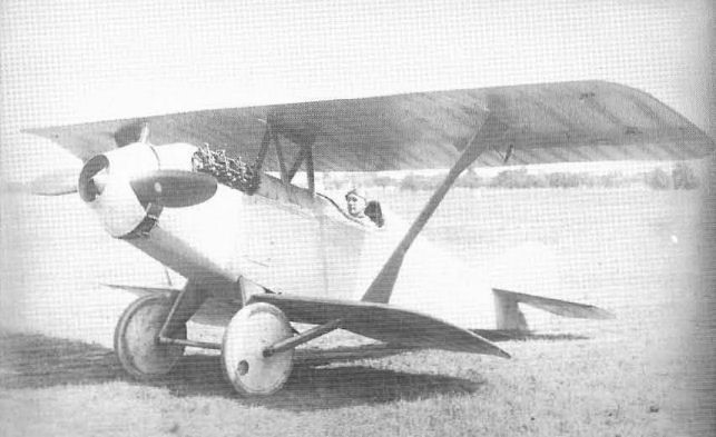
S-2 Wireless
The sole Curtiss S-2 Wireless single seat scout, seen here without its twin, broad-bladed propeller, along with the associated inner and outer spinners, the purpose of which was to funnel cooling air to the annular engine radiator revealed in this view.
S-2 Wireless Powerplant: 100 hp Curtiss OXX-2 Span 21 ft 10 in (6,65 m) (upper), 11ft 3 in (3,42 m) (lower) Aerofoil Eiffel 32 Empty Weight 805 lb (365 kg) Maximum speed 119 mph (191,5 km/h).
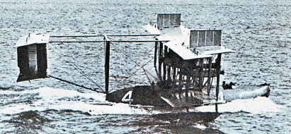
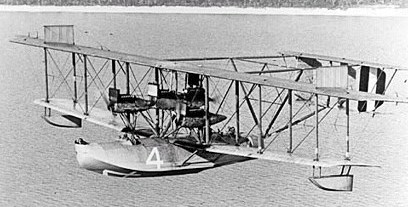
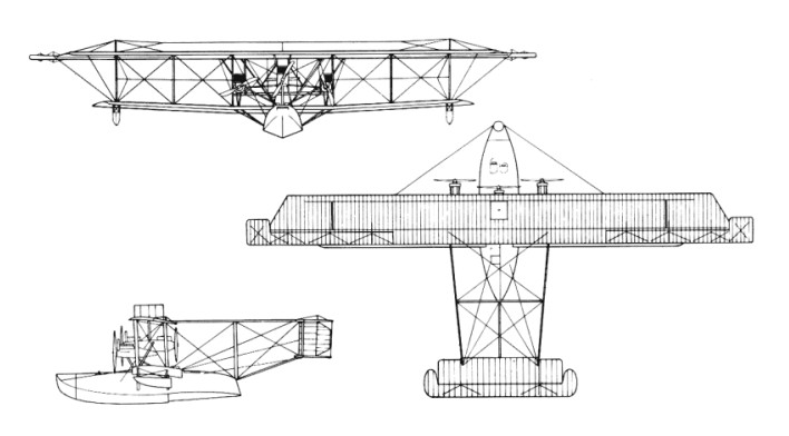
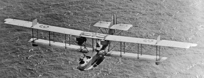
During 1917, the US Navy Bureau of Construction and Repair collaborated with Glenn Curtiss in an effort to produce a flying-boat that would be capable of crossing the Atlantic without difficulty and be immediately available for operations. Preliminary designs, drawn up by naval team which included Commander Jerome Hunsaker, were developed by Curtiss and his engineers. The selected configuration was a wide-span biplane with three tractor engines, a short hull to accommodate a crew of five, and a biplane tail supported on booms projecting from the upper wing and the rear of the hull. Detail design was carried out by the Curtiss staff, except for the hull which was the work of US Navy Commander Holden Richardson. Soon afterwards Curtiss received an order for production of the NC as it had by then been designated (NC for Navy-Curtiss). Four aircraft were to be built by Curtiss, and it was decided that the Naval Aircraft Factory would build six more. Existing factory space at the Curtiss Garden City, New York factory was greatly expanded with US Navy help for production of the NCs, which were to be taken by road in sections for final assembly at Rockaway Naval Air Station. When World War I ended only the NC-1 had been completed and the original purpose of the design no longer existed. Although the NAF NCs were cancelled, the US Navy decided to go ahead with the four Curtiss ‘boats which would be used in a transatlantic flight to the UK. It was felt that the publicity gained by such a flight would be of great value to the US Navy.
Three NC boats (NC-1, NC-3 and NC-4) left Trepassey Bay, Newfoundland on 16 May 1919, NC-2 having already come to grief. Both the NC-1 and the NC-3 came down at sea short of Horta in the Azores, which was to be the first stop. Neither could take off again, the NC-1 being abandoned and its crew taken off by ship, but the NC-3 was able to taxi in to Horta. Only the NC-4 completed the journey to Plymouth successfully, arriving on 31 May following stops at Horta, Ponta Delgada, Lisbon, and Ferrol del Caudillo. The total distance flown from take-off at Rockaway, New York on 8 May was 6317km, completed in 57 hours 16 minutes total flight time.
NC-1 Engines: 3 x 360-hp/268-kW Liberty inlines in tractor layout Later – four engines as three tractors and one pusher
NC-2 Engines: two tractors and one pusher Later two tractor/pusher tandem pairs
NC-3 As four-engined NC-l
NC-4 Engine: 4 x 400-hp / 298kW Liberty 12A inline piston Maximum take-off weight: 28,000 lb / 12,701 kg Empty weight: 7257 kg / 16,000 lb Wingspan: 38.40 m / 125 ft 12 in Length: 20.80 m / 68 ft 3 in Height: 7.44 m / 24 ft 5 in Wing area: 226.77 sq.m / 2440.93 sq ft Max. speed: 137 km/h / 85 mph at sea level Service ceiling: 760 m / 2500 ft Climb to 2,000 ft (610 m): 10 min 0 sec Endurance 14 hours 45 minutes.
The US Army Air Service staged two competitions, in late 1924 and early 1925, to find successors to the DH 4 series of observation and light bomber aircraft. The first Curtiss biplane to bear the name Falcon was the Liberty-powered Curtiss L-113 (Model 37). It was unsuccessful when evaluated in 1924 as the XO-1 in competition with the Douglas XO-2 but was accepted for production the following year when re-engined with a 380kW Packard 1A-1500. It was a conventional unequal-span biplane with a wing of wooden construction that incorporated sweep-back on the outer panels of the upper wing. The fuselage was built up from aluminium tubing with steel tie-rod bracing, and the tail unit included a balanced rudder; the fixed divided landing gear was of tailskid type. The Packard engine proved a failure, and the 102 production O 1s were fitted instead with various models of the 435 hp Curtiss D 12 (V¬1150) engine. The new biplane went into production as the O-1 (Model 37A) for observation duties with the US Army. The initial order was for 10 aircraft re-engined with a Curtiss D-12. One of these was completed later as the O-1A with a Liberty engine, and the first O-1 was converted to O-1 Special configuration as a VIP transport. Forty-five examples of the O-1B (Model 37B) were ordered in 1927, this first major production version incorporating such refinements as wheel brakes and an underbelly auxiliary fuel tank which could be jettisoned in flight. They were followed by four O-1C aircraft, part of the O-1B order, converted to serve as VIP transports by enlargement of the rear cockpit and the addition of a baggage compartment. (The designation O-1D was not used).
In 1929 the US Army ordered 41 of the O-1E (Model 37I) with V-1150E engines developed from the original Curtiss D-12. A number of other improvements included the introduction of oleo-pneumatic shock-absorbers, Freise ailerons, and horn balanced elevators. One O-1E was modified subsequently as a VIP transport becoming redesignated O-1F (Model 37J). The XO-1G (Model 38) replacing the twin Lewis guns on a Scarff mounting that equipped the earlier models by a single gun on a post mounting. Other modifications introduced redesigned horizontal tail surfaces and a steerable tailwheel.
The XO-1G was originally an O-1E which had been modified previously to contend as a new US Army basic trainer under the designation XBT-4 (Model 46).
XBT-4
The XBT-4 of 1930 was produced at the Curtiss-Wright experimental facility in Garden City in 14 days. For its training role, the rear cockpit is higher than previous models, and the squared cowling is sloped to give good visibility. A full thickness sponge rubber pad is mounted over the instrument panel with cutouts for the dials. The seats may be raised or lowered 7.5 in, and are tilted back at 13˚ from level. All cockpit mechanism is hidden behind wooden veneer walls.
Successful tests led to construction of 30 series examples of the O-1G with improved strearnlining, slightly smaller wings, and redesigned rear cockpits, were 16 km/h (10 mph) faster than the O 1B, bringing total O-1 production for the US Army to 127.
Two O 1 conversions (to O 1A and XO 11) to a 420 hp Liberty engine, 66 Liberty engined models were produced for the US Army.
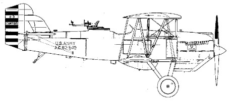
The O-1 Falcon and its variants saw a decade of service with the observation squadrons of the US Army Air Corps and ended their days with reserve National Guard units. The basic design was adapted also as the A-3 attack biplane which saw considerable use. The A 3, based on the O 1B was an attack version of the Falcon. It had two additional 0.30 in (7.62 mm) machine guns in the lower wings and could carry up to 91 kg (200 lb) of underwing bombs. The standard armament for most Falcons was four 0.30 in (7.62 mm) guns, two in the wings and a twin mount on a Scarff ring in the rear cockpit. There were also export versions and a number of commercial Falcons.
A-3
Several experimental Falcons flew with 600 hp Curtiss V 1570 Conqueror engines. They included the XO 13 and XO 13A (two converted O 1s) for the 1927 national air races; one O 13B; three YO 13Cs, otherwise similar to the O 1E; one YO 13D (super¬charged Conqueror); one XO 16, a Con¬queror engined O 11 with Prestone (ethylene glycol) cooling; and one Y10 26, similar to the O 1E but with a GIV 1570A geared Con¬queror and modified cooling system. How¬ever, the only Conqueror powered production version, was the O 39, with Prestone cooling and a smaller rudder, but otherwise similar to the O 1G. Ten of these were built in 1932. Other one off engine testbeds included the XQ 12 (Pratt & Whitney Wasp), con¬verted from an O 11, and XO 18 (Curtiss Chieftain). Other conversions, not involving an engine change, were four O 1Bs to O 1C unarmed VIP transports; one O 1E to an unarmed O 1F; another O 1E to XBT 4 basic trainer configuration, this later becoming the prototype for the O 1G; and one O 11 to O-¬11A (incorpora~ the improvements of the O 1E). Except for the O 1C and O 1F, standard armament on the observation Falcons was four 0.30 in (7.62 mm) machine guns: two fixed, forward firing guns in the nose and two on a Scarff ring in the rear cockpit. Between 1927 30, Curtiss also produced 154 attack versions (76 A 3s, based on the O 1B, and 78 A 3Bs, based on the O 1E). These had two additional 0.30 in (7.62 mm) guns in the lower wings and could carry up to 91 kg (200 lb) of underwing bombs. There was also, in 1928, one XA 4, equivalent to the A 3, but with a 421 hp R 1340 1 Wasp engine.
Wright Cyclone powered Falcon
Variants
U.S. Army Air Corps
A-3 Model 44, attack aircraft version of O-1B, armed with two 0.30 in (7.62 mm) machine guns and 200 lb (91 kg) of bombs; 66 built for the USAAC. A-3A Six A-3s converted into trainers. A-3B Model 37H, attack version of O-1E, with six machine guns, including two mounted in wings; 78 built.
Curtiss XA-4 Falcon
XA-4 One A-3 with a Pratt & Whitney R-1340-1 Wasp radial piston engine. Scrapped in March 1932, but the design was the basis for the naval variants. A-5 Proposed A-3 variant with Curtiss V-1570 Conqueror engine A-6 Proposed A-3 variant with Curtiss H-1640 Chieftain engine
XBT-4
XBT-4 Model 46, one O-1E converted into a basic trainer for the USAAC. XO-1 Liberty 12A powered Prototype, later modified to use a Packard 1A-1500, one built. O-1 Model 37A, two-seat observation aircraft, the first production model, ten built. One converted into the O-1 Special VIP transport. O-1A Two-seat observation aircraft, powered by the Liberty piston engine, one built. O-1B Model 37B, first major production version, powered by Curtiss D-12D (V-1150-3) engine; 45 ordered, 25 built and 20 diverted on the production line to the A-3. O-1C Four O-1Bs converted into VIP transports. O-1E Model 37I, variant powered by 435 hp (324 kW) Curtiss D-12E (V-1150-5) piston engine; 41 built. O-1F Model 37J, one O-1E converted into VIP transport. O-1G Model 38, final O-1 variant, powered by a 712 hp (531 kW) Wright R-1820F-2 Cyclone engine; 30 built for USAAC. XO-11 Two O-1 modified as O-11 prototypes. O-11 O-1 airframe powered by the Liberty V-1650 piston engine; 67 built concurrently with the O-1s. XO-12 One XO-11 prototype redesignated XO-12. XO-13 O-1 fitted with 720 hp (540 kW) Conqueror engine for the 1927 National Air Races. XO-13A Second XO-13, fitted with wing skin radiators. O-13B One O-1C fitted with a Conqueror engine, tested as an observation aircraft, and provided to Secretary of War. YO-13C Three O-1Es re-engined with 600 hp (450 kW) direct-drive Conqueror engines. YO-13D One O-11 fitted with supercharged Conqueror engine. XO-16 One O-11 with Prestone cooling system. XO-18 One O-1B testbed for Curtiss H-1640 Chieftain engine. Y1O-26 One O-1E fitted with a geared Conqueror engine. O-39 O-1G refitted with a Conqueror engine and cockpit canopy; ten built.
U.S. Navy and Marine Corps Marine Corps Curtiss OC-2 Falcon, c. 1929 The XF8C-2 prototype The XF8C-4 prototype
A-3 Helldiver Registry name of XF8C-8, not adopted by USN. A-4 Helldiver Civil version of XF8C-8 for use by Assistant Secretary of Navy David Ingalls. Later redesignated XF8C-7. XF8C-1 Model 37C variant developed from XO-12; two built for the U.S. Navy. F8C-1 Falcon Model 37C powered by the 420 hp (310 kW) Pratt & Whitney R-1340 Wasp radial piston engine; four built in 1928 for the U.S. Marine Corps as light bombers, fighters and observation aircraft, later redesignated OC-1. XF8C-2 Model 49, one prototype for F8C Helldiver. Original crashed on first factory flight and was replaced by Curtiss with a second bearing identical sn. F8C-3 Falcon Second production batch of Navy Falcons; 21 built for USN/USMC in 1928, later redesignated OC-2. XF8C-4 Second Helldiver prototype, modified tail skid assembly. F8C-4 Helldiver Model 49B, production dive-bomber variant for the USN/USMC; 25 built, later designated O2C. F8C-5 Helldiver Model 49B with ring cowling; 63 built in 1930–31, later designated O2C-1. XF8C-6 Two F8C-5s modified with superchargers, slats, and wing flaps; one later modified as O2C-2. XF8C-7 Redesignation of A-4 Helldiver, later redesignated XO2C-2. XF8C-8 Two prototypes built with canopy-enclosed front cockpit, later redesignated O2C-2. O2C-1 Helldiver Redesignation of 63 F8C-5; 30 production O2C-1s in 1931. O2C-2 Helldiver Redesignation of XF8C-8s and one XF8C-6. XOC-3 One XF8C-1 prototype fitted with a Chieftain engine. XF10C-1 O2C-2 re-engined with a R-1510 engine, also temporary designated XS3C-1.
Civil and export
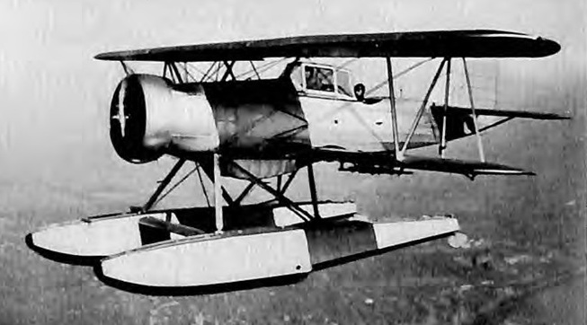
Civil Falcon 20 civil versions: Conqueror Mail plane; D-12 Mailplane; Lindbergh Special, sold to Charles Lindbergh; Liberty Mailplane, 14 single-seat mailplanes, powered by a Liberty piston engines, sold to National Air Transport. Export Falcon also South American D-12 Falcon. One seaplane version of the O-1B was sold to Colombia, followed by an order for 15 more. Another 10 Model 35Fs were sold to Peru. Colombia Cyclone Falcon Model 37F fitted with the 712 hp (531 kW) Wright Cyclone radial piston engine. 100 built for Colombia. Chilean Falcon O-1E design built under license in Chile, 10 later sold to Brazil. One example ended up in Paraguay as passage fee for the remaining aircraft. It operated mostly as a VIP transport, but made at last one reconnaissance flight over the Chaco war fields armed with two 7.7 mm (0.303 in) machine-guns from a Potez. Bolivia Cyclone Falcon Similar to Colombian Falcon, it was fitted with the 712 hp (531 kW) Wright SR-1820F-2 Cyclone radial piston engine. A total of nine were built for Bolivia in some odd variants from the Colombian ones. Bolivian Cyclone Falcons mounted one frontal .30 MG and most also one rear .30 MG instead of the two wing-mounted ones. Two had semi-cockpit canopies over pilots cockpit; two had windscreens instead of canopy in both cockpits, these two had no ring mount for rear machine gun.
Specifications
Curtiss O 1B Span: 11.58 m (38 ft) Length: 8.64 m (28 ft 4 in) Gross weight: 1989 kg (4385 lb) Maximum speed: 218 km/h (135.4 mph)
Curtiss O-1E Engine: 1 x 324kW Curtiss V-1150E inline piston engine Take-off weight: 1972 kg / 4348 lb Loaded weight: 1325 kg / 2921 lb Wingspan: 11.58 m / 37 ft 12 in Length: 8.28 m / 27 ft 2 in Height: 3.20 m / 10 ft 6 in Wing area: 32.79 sq.m / 352.95 sq ft Max. Speed: 227 km/h / 141 mph Ceiling: 4665 m / 15300 ft Range: 1014 km / 630 miles Armament: 1 x 7.62mm machine-gun
Curtiss A 3B Span: 11.58 m (38 ft) Length: 8.28 m (27 ft 2 in) Gross weight: 2030 kg (4475 lb) Maximum speed: 224 km/h (139 mph)
In August 1920, Curtiss the company was forced into receivership. Clement Keys, a Canadian financier, obtained funds to manage the company’s debt and led it again to sound financial status. The Buffalo facility became the major facility, and the company remained the largest U.S. aircraft company through the 1920s. Its racing planes, including the CR-1 and CR-3, won several competitions.
The active cooperation between Curtiss and the military on racers began in 1921, with the appearance of the R-1 (No. A-6080). This biplane was powered by a 400 hp Curtiss D-12 engine which enabled Curtiss test pilot Bert Acosta to win the 1921 Pulitzer Trophy Race at 177 mph. For 1922, the Navy was ready with that airplane and its sister-ship-the R-2 (No. A-6081), Lt. Harold Brow placed third in the 1922 Pulitzer Race in the new airplane, while Lt. AI Williams was fourth in the older ship. Both airplanes were then converted into seaplanes by the addition of twin pontoons; as R-3s they captured the Schneider Trophy. Lt. David Rittenhouse was the winner of the prestigious event in A-6081 at 177 mph, and Lt. Irvine was second at 173 mph.
The single CR-1 of 1921, A6080, had conventional gear. It later became a CR-3.
The single CR-2 (original designation for CR-4) of 1921, A6081, was flown by USN Lt Harold Brow to third place in the 1922 Pulitzer race, in which Curtiss ships took the first four places. It later became a CR-3.
The Schneider Trophy never experienced any casualties during competition, but several pilots were killed training for the races. U.S. citizens Harmon J. Norton in 1923 were killed in a Curtiss CR-3 and Franck Connaut in 1926.
A CR-3 was winner of the 1921 Pulitzer trophy race piloted by Bert Acosta, at 176.7 mph.
In 1923 the Schneider Trophy Contest at Cowes, Isle of Wight was won by an American Curtiss CR-3 racing seaplane at a speed of 285km/h, piloted by Lieut David Rittenhouse. Close behind was a second CR-3 flown by Lieut Rutledge Irvine with a speed of 279.16km/h. The only other aircraft to complete the 344.69km course was Britain’s Supermarine Sea Lion III, powered by a Napier Lion engine which was almost 19% more powerful than the Curtiss D-12 carrying the CR-3 to victory. Richard Fairey realised that the Curtiss engine, in combination with a Curtiss-Reed propeller, was a most significant factor in this American success.
The CR-4s of 1923 were CR-1 with pontoons and CR-2 redesignated and modified to an unknown extent. The two were A6080/6081. A CR-4 set seaplane speed record of 188mph in 1924.
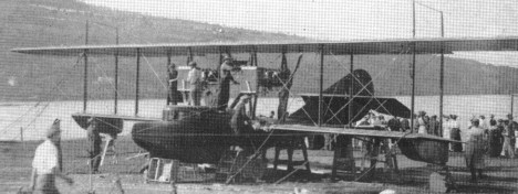
The two-engine Curtiss flying boat America was built in 1914 for an attempted flight across the North Atlantic. Before it could be completed Britain was at war with Germany. John Porte, the intended pilot, returned to the Navy, closely followed by the America, which became the forerunner of all the large Curtiss flying boats. By July 1916 first examples of a larger Curtiss flying boat design began arriving in England. Designated H.8, these were quickly modified to accept more powerful twin 250 hp Rolls Royce engines, and redesignated Curtiss H.12s, or ‘Large Americas’. 20 similar models that were either modified or manufactured in England, marking the beginning of England’s flying-boat industry. The aircraft were used extensively for antisubmarine patrol.
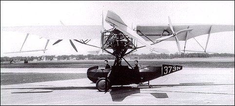
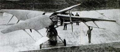
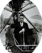
American engineer, Virginian M. B. Bleecker idea of a rotor driven by airscrews on the blades differed from the others in that his airscrews did not have individual engines but were connected by gearing and chains to a single central Pratt and Whitney 420hp radial power unit.
As constructed by the Curtiss Wright Corporation in 1926, each of the wing-shaped blades had auxiliary trailing strut-mounted control surfaces which, when operated collectively, were to make the aircraft rise or descend, and when operated differentially, to ensure stability. The landing gear consisted of three fixed wheels.
Designer Maitland B. Bleecker at the controls
This helicopter successfully made a few “hops” inside the hangar where it was built, but it was abandoned because of its lack of stability and the failure of attempts to eliminate vibration.
Curtiss-Bleecker Engine: 1 x Pratt and Whitney, 420hp Rotor diameter: 14.42m Gross weight: 1500kg Number of seats: 2