A USAAC contract placed on 14 May 1927 called for five aircraft with airframes essentially similar to that of the P-1C, but powered by a turbo-supercharged Curtiss V-1150-4 12-cylinder water-cooled engine. The first of these was delivered in January 1928 as the XP-5, with the remaining four following as P-5s by June 1928. Dubbed Superhawk by the manufacturer, the P-5 had a side-mounted exhaust-driven turbo-supercharger with which it attained a service ceiling of 9450m. Warm air was ducted from the exhaust manifold to the cockpit, the heat being contained by a “cape” which snapped around the cockpit rim and fitted closely about the pilot. They had a consid¬erably higher than the maximum ceiling of the P-1A but their low level performance was inferior. Two of the P-5s were lost in accidents shortly after delivery, but the remaining two served with the 94th Pursuit Squadron until April 1932. The V-1150-4 (D-12F) engine was rated at 435hp and armament comprised two 7.62mm machine guns. Provision existed for the carriage of bombs beneath the fuselage.
Engine: turbo-supercharged Curtiss V-1150-4 (D-12F) 12-cylinder water-cooled, 435 hp Wingspan: 9.60 m / 31 ft 6 in Length: 7.21 m / 23 ft 8 in Height: 2.82 m / 9 ft 3 in Wing area: 23.41 sq.m / 251.98 sq ft Take-off weight: 1519 kg / 3349 lb Empty weight: 1143 kg / 2520 lb Max. speed: 267 km/h (166 mph) at 7620 m (25 000 ft) Armament: two 7.62mm machine guns.
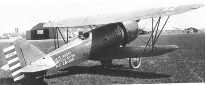
The first radial-engined Hawk resulted from the mating of a P-1A airframe with a 390hp Curtiss R-1454 engine as the XP-3 in October 1926. The failure of the Curtiss engine led to its substitution by a 410hp Pratt & Whitney R-1340-9, with which it was tested in April 1928 as the XP-3A. Five production examples had been ordered in December 1927 as P-3As, deliveries commencing in September 1928.
The P-3A was powered by the R-1340-3 version of the Wasp, also rated at 410hp, and the first production example was flown with various experimental cowlings as the second XP-3A. Both this and the original XP-3A were eventually to become XP-21s, the second XP-3A undergoing further conversion (after testing as an XP-21) to P-1F standards. Armament of the P-3A comprised two 7.62mm machine guns and this type was fitted with a Townend ring after service entry. Provision existed for the carriage of bombs beneath the fuselage.
P-3A Engine: Pratt & Whitney R-1340-3 Wasp, 410hp Take-off weight: 1265 kg / 2789 lb Empty weight: 887 kg / 1956 lb Wingspan: 9.63 m / 31 ft 7 in Length: 6.83 m / 22 ft 5 in Height: 2.67 m / 8 ft 9 in Wing area: 23.41 sq.m / 251.98 sq ft Max. speed: 246 km/h / 153 mph Armament: two 7.62mm machine guns
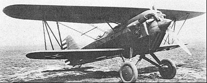
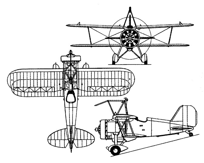
With its origins in the Model L-18-1 (which stemmed the PW-8 US Army production fighters), the Curtiss model 34 / XPW-8A became the P-1 prototype. A biplane single-engine, single-seat fighter with fixed landing gears, tapered-wings, wheel brakes and more powerful engines, produced a large number of variants for the Curtiss company.
Armed with an array of .303 caliber machine guns, the aircraft had a flight ceiling of over 20,000 feet and speeds in excess of 150 miles per hour.
On 7 March 1925, Curtiss was awarded a contract for 15 production examples of the model 34A XPW-8B as the P-1, this being the first fighter to which the company assigned the name Hawk. Externally similar to the XPW-8B, the P-1 was of mixed construction with wooden wings and steel-tube fuselage with fabric skinning, and was powered by a 435hp Curtiss V-1150-1 12-cylinder water-cooled engine. The first aircraft became the XP-17, and the final five aircraft were completed as model 34B P-2s, three of these later being converted to P-1A standards.
P-1A 1931
They were delivered to the 27th and 94th Pursuit Squadrons from August 1925, with 435 hp Curtiss V 1150 1 12 cylinder liquid cooled V type engines.
Curtiss P-1A 1926
Follow-on contracts were placed on 9 September 1925 for Model 34G 25 P-1As (which had a 7.62cm longer fuselage), revised engine cowling and slightly heavier all up weight. They were delivered from April 1926, they served with the 17th, 27th and 94th Pursuit Squadrons. One each was used for XP-6A, XAT-4A, XP-3A, AND XP-22.
Next production version was the P 1B (again an order for 25, in August 1926), powered by a 435 hp V 1150 3 engine, which had larger main wheels and a modified radiator.
The 33 P-1Cs, ordered in October 1928 and delivered by April 1929, also utilized the V 1150-3 engine and were fitted with wheel brakes.
All these sub-types carried an armament of two 7.62mm guns.
In the meantime, the USAAC had ordered advanced trainers utilising the same airframe. These comprising 35 AT-4s (180hp Wright V-720), five AT-5s and 31 AT-5As (220hp Wright R-790), and, in 1929, these were re-engined with the V-1150-3, all 35 AT-4s becoming P-1Ds and four AT-5s and 24 AT-5As becoming P-1Es and P-1Fs respectively. One other P 1F resulted from reconverting the XP 21, which had previously been a P 3A. These conversions were essentially similar to the P-1B apart from having only one gun. Four P-1s were supplied to Bolivia, one P-1A went to Japan, and eight P-1As and eight P-1Bs were supplied to Chile.
The P-2s (model 34B) were the last five machines from the original P-1 contract, but powered by 505 hp V 1400 engines; three of these P 2s were converted later to P-1A standard. One became the XP-6.
F6C
The Curtiss F6C Hawk series of aircraft was the US Navy/Marine model of the US Army’s P-1 Hawk series. The US Navy began fielding the P-1 it as a carrier-based aircraft while the US Marines operated it as a land-based fighter.
F6C
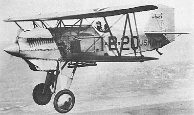
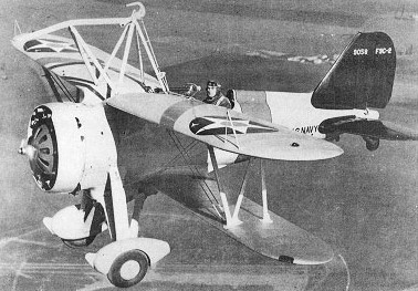
In March 1925, the US Navy ordered nine P-1s with provision for float operation as (Curtiss Model 34) F6Cs (the F5C designation was not assigned, to avoid confusion with the F-5 flying boat). Five of these were delivered as Model 34C F6C-1s with provision for float undercarriage, but no arrester gear, and four (with arrester hooks) as Model 34D F6C-2s. These had 400 hp Curtiss V¬1150 similar power plant to the USAAC’s P-1 and the standard two 0.30 in (7.62 mm) gun armament. Two of the F6C-1s were later converted to -2 standard. The last four became F6C-2s. In 1927, 35 additional aircraft were ordered, these using the P-1A airframe and being designated F6C-3. Two F6C-1s were converted to -3 standard and one F6C-3 was fitted with a Pratt & Whitney R-1340 radial as the XF6C-3.
A batch of 35 incorporating these improvements was ordered in 1927; these, plus two others converted from F6C 1s, entered with the USN and USMC in 1928 as the Model 34E F6C 3. One became the F6C-6 racer and later became the XF6C-6 monoplane. A twin float F6C 3 won the Curtiss Marine Trophy race in 1930 at a speed of 264.1 km/h (164.1 mph).
Two F6C 2s (the balance of the F6C 1 contract), fitted with arrester hooks and strengthened landing gear, were used for deck trials.
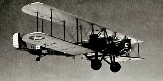
The US Navy had decided, by 1927, to standardise on air-cooled radial engines, which were more easily maintained at sea than liquid-cooled inline engines. After trials with a Pratt & Whitney R-1340- engined F6C-3, a production contract was placed for 31 fighters powered by this 410hp radial as F6C-4s (model 34H). The first of these aircraft, which was retained for test purposes was assigned the temporary designation XF6C-7, and deliveries commenced in February 1927. Possessing the same twin-gun armament as its predecessors, the F6C-4 proved more manoeuvrable than the V-1150- powered models, but was becoming obsolescent by the time that it was delivered. The F6C-4 were issued to one squadron only (in the USS Langley) for operational use until 1930; others were put into service as advanced trainers.
A total of 75 of the F6C series Hawks were produced for the US Navy. Experimental F6C models were: XF6C-5 (first F6C-1 fitted with a 525hp Pratt & Whitney R-1690 Hornet) XF6C-6 (an F6C-3 converted to parasol monoplane configuration for the 1930 Thompson Trophy race) F6C-6 (an F6C-3 modified for 1929 air races and returned to -3 standard) XF6C-7 (an F6C-4 with an inverted air-cooled Ranger SGV-770 engine).
Curtiss P-1B Take-off weight: 1 330 kg Empty weight: 955 kg / 2105 lb Wingspan: 9.63 m / 31 ft 7 in Length: 6.91 m / 22 ft 8 in Height: 2.72 m / 8 ft 11 in Wing area: 23.23 sq.m / 250.05 sq ft Range: 966 km / 600 miles Maximum speed: 253 km/h (157 mph).
Curtiss P-2 Engine: 505 hp V 1400 engines
Curtiss F6C-3 Hawk Engine: 1 x Curtiss D.12 Conquerer water-cooled inline, 400hp. Length: 22.83ft (6.96m) Wingspan: 31.59ft (9.63m) Wing area: 23.41 sq.m /251.98 sq ft Height: 3.25 m / 10 ft 8 in Maximum Speed: 154mph (248kmh; 134kts) Maximum Range: 351miles (565km) Service Ceiling: 20,299ft (6,187m; 3.8miles) Armament: 2 x .303 inch machine guns Accommodation: 1 Empty Weight: 2,161lbs (980kg) Maximum Take-Off Weight: 3,349lbs (1,519kg)
Curtiss F6C-4 Span: 9.60 m (31 ft 6 in) Length: 6.86 m (22 ft 6 in) Gross weight: 1263 kg (2784 lb) Maximum speed: 249 km/h (155 mph).
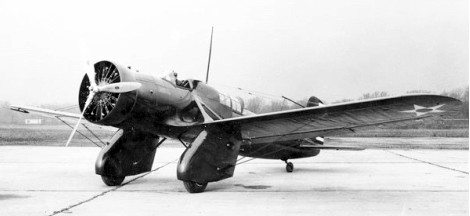
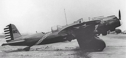
Curtiss won a contract for five service test YA-8 (Model 59A) aircraft on 29 September 1931, and one YA-8 was reworked as the experimental YA-10 (Model 59B) with a 466kW radial engine. The liquid-cooled Curtiss “Conqueror” engine was removed and replaced with a Pratt & Whitney air-cooled radial engine. The conversion was completed by September 1932 with comparable performance statistics to the original A-8 platform, and the aircraft was re-designated YA-10 because of the engine change.
All remaining A-8B’s on order (some 46 total) with their Conqueror liquid-cooled engines were now changed to include the replacement Pratt & Whitney radial powerplant. The new production designation of A-12 (Model 60) was then assigned to mark these models. Though often designated with the “Shrike” name, the aircraft was formally known simply as the “A-12” in USAAC nomenclature. Shrike was an official Curtiss company name assigned to its A-12 product.
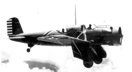
First appearing in 1933, these aircraft retained the open pilot’s cockpit with faired headrest which had been introduced on the A-8 production batch, and carried the same machine-gun armament and bombload. In an attempt to improve co-operation between pilot and observer a major modification had been introduced, the rear cockpit being moved forward with its glazed covering forming a continuation of the fuselage decking immediately behind the pilot’s cockpit.
An antenna structure rose high atop the fuselage, above and between the two cockpit positions. The pilot sat behind angled windscreens, complete a forward instrument panel and open sides revealing wiring, cables and piping. The fuselage itself was of tubular design and was made up of all-metal construction. With a fixed undercarriage with faired-over main landing gears – one positioned under each wing – and a conventional tail wheel, the wings were low-mounted monoplane assemblies with noticeable cable bracing and struts with slight dihedral. Wings were also of all-metal construction though the ailerons were covered over in fabric. The Wright R-1820-21 Cyclone radial piston engine of 690 horsepower powered a three-bladed propeller. Tail surfaces were also of all-metal construction but the rudder and elevator components were covered over in fabric.
Standard armament for the A-12 Shrike included a battery of 4 x .30 caliber machine guns in a fixed forward-firing set up with two guns fitted into each landing gear spat (600 rounds of .30 caliber ammunition allotted to each gun). A C-4 gunsight was afforded the pilot. The rear gunner had access to a .30 caliber machine gun on a flexible mounting to protect the aircraft’s “six”. Aside from the machine gun armament, the A-12 was cleared for light bombing duty and could field up to four 122lb conventional drop bombs under the wings. In place of these munitions, the Shrike could also utilize up to 10 x 30lb fragmentation bombs or flares for marking targets at night. A 52-gallon external fuel tank could be used in place of the bombs and could be jettisoned when empty. Interestingly enough, the main fuel tank aboard the A-12’s fuselage could also be jettisoned via a hand crank.
The A-12 was delivered to the USAAC in 1933. Initial examples became a single production model and two service test aircraft. A-12’s eventually made up the mount of choice for the 3rd Attack Group and 37th Attack Squadron of the 8th Pursuit Group. The aircraft was eventually shipped off the mainland and ended up in Hawaii via Wheeler Field and then later at Hickam Field. Incidentally, Hickam Field itself was named after Lieutenant Horace Meek Hickam whom died while attempting to land his A-12 Shrike at Fort Crockett in Texas.
Operationally, the A-12 was never used in anger by American forces. Though nine A-12s still remained in service at the attack on Pearl Harbor, the aircraft never went airborne in defense of the island and the type was dropped from service soon afterwards. A-12’s maintained a limited capacity as reconnaissance platforms as well and could be modified for the role through the use of onboard cameras.
The Chinese nationalist government bought at least 20 of an export version of the A-12 in 1936. These A-12’s sported a more powerful version of the air-cooled engine in the Wright SR-1820F-52 of 775 horsepower supplying a better maximum speed of 182 miles-per-hour. These saw some action against the Japanese in 1937-8.
Some A-12’s underwent further periods of notable development. One such conversion involved the addition of ski-like implements in place of the landing gear fairings to make the A-12 more “bad-weather friendly”. Not only did this allow the Shrike to operate from icy or snowbound airstrips, it provided for viable landings and take-off operations from dirt, grass and paved-over runways as well. Another such development involved adding inflatable air bladders to the sides of the fuselage. Should the crew and aircraft be forced into an emergency landing over water, the air bladders could be filled to allow the A-12 to stay above water until help arrived. These implements were never put into production A-12s.
Curtiss A-12 (Shrike) Engines: 1 x Wright R-1820-21 Cyclone radial, 690 hp (515-kW) Length: 32 ft 3 in (9.83m) Wing span: 44 ft 0 in (13.41m) Wing area 284.0 sq ft (26.38 sq.m) Height: 9 ft 4 in (2.84m) Maximum Speed: 177mph (285kmh; 154kts) at sea level Maximum Range: 521miles (838km) Service Ceiling: 15,157ft (4,620m) Iinitial climb rate: 1170 ft (357 m) per minute Armament: 4 x .30 caliber machine guns in fixed-forward positions. 1 x .30 caliber machine gun in rear flexible mounting. Optional: 4 x 122lb bombs 10 x 30lb fragmentation bombs 1 x 52 gallon external fuel droptank Accommodation: 2 Hardpoints: 4 Empty Weight: 3,898lbs (1,768kg) Maximum Take-Off Weight: 5,756lbs (2,611kg)
Curtiss won a contract for five service test YA-8 (Model 59A) aircraft on 29 September 1931, and one YA-8 was reworked as the experimental YA-10 (Model 59B) with a 466kW radial engine. The liquid-cooled Curtiss “Conqueror” engine was removed and replaced with a Pratt & Whitney air-cooled radial engine. The conversion was completed by September 1932 and the aircraft was re-designated YA-10 because of the engine change. The performance of the YA-10 was about the same as the A-8, but the air cooled radial engine was favoured over a liquid cooled engine. After testing was complete, the Army changed the order for 46 A-8Bs (with geared “Conqueror” engines) to A-12s. The Curtiss A-12 was equipped with a Pratt & Whitney radial engine and was essentially a production version of the YA-10. The YA-10 remained in service through the late 1930s. After service testing, the aircraft was assigned to the 3rd Attack Group for operational service. In the summer of 1934, the YA-10 was assigned to the Command and General Staff School. It was scrapped in early 1939.
Engine: 1 x 470kW Pratt & Whitney R-1690-9 (R-1690D) Hornet radial Take-off weight: 2783 kg / 6135 lb Wingspan: 13.5 m / 44 ft 3 in Length: 9.9 m / 32 ft 6 in Height: 2.75 m / 9 ft 0 in Max. speed: 280 km/h / 174 mph Cruise speed: 238 km/h / 148 mph Ceiling: 4570 m / 15000 ft Range: 800 km / 497 miles
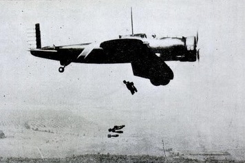
To find a successor to its attack biplanes, the US Army Air Corps issued a 1929 requirement for a high-speed monoplane, and Curtiss responded with its Model 59 design that first flew in proto¬type form during June 1931 with the 600-hp (447-kW) Curtiss V-1570-C inline engine with a radiator beneath the nose, slightly forward of the wing leading edge. The first Curtiss all-metal low-wing monoplane, with such advanced features as automatic leading-edge slots and trailing-edge flaps. The wing was strut-and wire-braced, and the main landing gear comprised two fully-enclosed trousered units, these fairings housing also two 7.62mm machine-guns. Pilot and observer-gunner were accommodated in widely separated cockpits, the former under a fully enclosed canopy and the latter protected by an extended windscreen. Power was provided by a 447kW Curtiss V-1570C inline engine.
These entered service with the 3rd Attack Group in April 1932 as the US Army’s first monoplanes. Another 46 Shrikes were ordered with the designa¬tion A-8B, but because of maintenance difficulties with the A-8s’ inline engines, the aircraft were recast as radial-engined A-12s. Curtiss won a contract for five service test YA-8 (Model 59A) aircraft on 29 September 1931, and these were followed by eight Y1A-8 machines in 1932. Both YA-8s and Y1A-8s had open pilot’s cockpits. All were later redesignated A-8 except for one YA-8 which was reworked as the experimental YA-10 (Model 59B) with a 466kW radial engine and one Y1A-8 which became the Y1A-8A with a 503kW V-1570-57 geared engine and a redesigned wing. The A-8s, powered by Prestone-cooled V-1570-31 engines each of 447kW, went into service with the 3rd Attack Group at Fort Crockett, Texas in April 1932. That eight months before the Boeing P-26A Peashooter. The US Army had ordered a further 46 Shrikes under the designation A-8B, but maintenance problems with the liquid-cooled engines of the A-8s led to the new aircraft being powered by Wright R-1820-21 radial air-cooled engines of 500kW, resulting in the new designation A-12 (Model 60). After long service with the US Army’s attack groups the Shrikes were relegated to second-line units in 1939, but nine A-12s still remained in service in Hawaii when Pearl Harbor was attacked in December 1941.
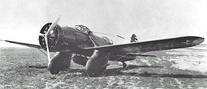
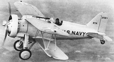
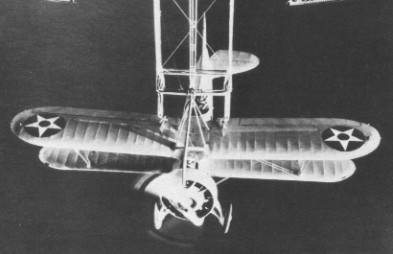
Designed to meet a lightweight shipboard fighter requirement – other contenders being the Berliner Joyce XFJ-1 and General Aviation XFA-1 – the XF9C-1 was flown on 12 February 1931. It failed to gain acceptance as a carrier-based aircraft, but its small dimensions commended it for use from the dirigibles Akron and Macon which had been designed with internal hangar bays. The XF9C-1 was subsequently fitted with the so-called “skyhook” which engaged the retractable trapeze featured by the dirigibles, some directional instability resulting from the hook dictating the enlarging of the vertical tail surfaces. A second prototype, the XF9C-2 with single-strut main undercarriage members, was built at Curtiss expense prior to the placing of a US Navy contract for six F9C-2s, which featured a similar tripod undercarriage strut arrangement to the XF9C-1. he XF9C-2 was purchased by the US Navy and modified to F9C-2 standard. The F9C-2 was powered by a 438 hp Wright R-975-E3 radial engine and carried an armament of two 03-in (7,62-mm) Browning machine guns.
XF9C-1
Originally intended to provide fighter protection for the dirigibles, the F9C-2s were used primarily to extend the reconnaissance capabilities of the parent craft. The Akron received her complement of aircraft in June 1932, ten months after she was commissioned and tests soon realized her potential as an aircraft carrier whose fighters could patrol beyond the horizon, controlled by radio from an airborne command post aboard the airship. Akron went down in the Atlantic on 3 April 1933 during a violent storm, but the parasite experiments continued with Macon until 12 February 1935, when her top fin disintegrated inflight, half her helium escaped and Macon went into the sea together with four of the F9C-2s. The US Navy’s affair with airships and trapeze aircraft was finished.
F9C-2 Engine: 438 hp Wright R-975-E3 radial Span, 25 ft 5 in (7,75 m) Length, (6,27 m) Height: 10 ft 1 11.5 in (3,34 m). Wing area, 173 sq ft (16,07 sq.m). Empty weight, 2,089 lb (947 kg) Loaded weight, 2,770 lb (1 256 kg) Max speed, 176 mph (284 km/h) at 4,000 ft (1220 m) Initial climb, 1,700 ft/min (8,63 m/sec) Range, 350 mls (563 km) Armament: two 0.30-in (7,62-mm) Browning machine guns.
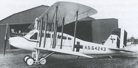
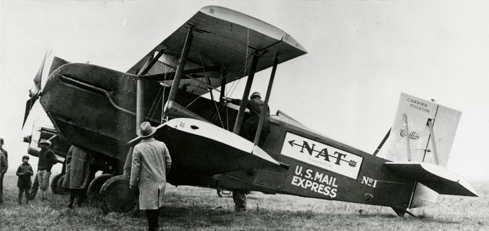
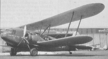
In 1925 the U.S. Postal Service felt they had excellent operational service with converted Airco D.H.4 biplanes. The eight-year-old designs were considered antiquated by this time, however, and a modern purpose-built machine was desired. While most manufacturers started to build new generation passenger aircraft with mail cargo capability, the Curtiss Carrier Pigeon was the first clean-sheet design specifically made for U.S. air-mail service. The aircraft was intended to be sold directly to the Postal Service, but new legislation that opened up outside contracts brought on a slew of competing models.
The Carrier Pigeon was drawn up to meet or exceed the original postal specifications. Strength, serviceability, and ease of maintenance were the three core design criteria. It was intended to provide service on the night-time runs between Chicago and New York, with only one stop. The plane was built to take advantage of the powerful and plentiful 400 hp Liberty L-12 engine to meet Postal specifications. Up to 40,000 airmail letters could be carried in the 1,000 lb capacity cargo hold.
The fuselage was a welded steel tube frame covered in fabric. The upper and lower wings were interchangeable and used solid, unspliced spruce spars. The rudder, ailerons, and elevators were also interchangeable, which reduced spares counts. The hinges used heavy replaceable bronze pins to reduce wear.
The watertight cargo hold was at the center of gravity so the aircraft could accommodate a range of loads without affecting the balance. The landing gear used rubber doughnut suspension. The fuel tank could be jettisoned in case of an emergency. A seven quart fire extinguisher was plumbed to the engine compartment for suppression of inflight fires. The pilot could choose between wheel or stick control based on his preference.
A prototype Curtiss Carrier Pigeon flown by Charles S. (Casey) Jones placed 7th in the 1925 Edsel B. Ford Reliability Tour. Out of 17 starters, 11 aircraft including the Carrier Pigeon completed with a perfect score, netting a $350 prize. Henry Ford waited at the finish line to greet the winners of the 1,900 mile endurance test.
The Carrier Pigeon was used by National Air Transport Inc. At the time, both Curtiss and NAT were owned and controlled by Clement Keys. Ten Carrier Pigeons were put into service with 35 surplus Liberty engine spares. NAT used the Carrier Pigeon for the Contract Air Mail CAM-3 (Chicago-Dallas) route. The first recorded service was on May 12, 1926 with the route between Chicago, Illinois and Dallas, Texas. Stops were scheduled in Moline, Illinois, Saint Joseph, Missouri, Kansas City, Missouri, Wichita, Kansas, Oklahoma City, Oklahoma and Fort Worth, Texas. The maiden flight was piloted by D A Askew, R L Dobie, R H Fatt, Lawrence H Garrison, P E Johnson, H L Kindred and Edmund Matucha. These pilots logged 776,351 miles of flight in the first year without an accident or loss of any mail.
NAT invested $10 million competing for the night-time Chicago to New York route (CAM 17). NAT started service on September 1, 1927 using Carrier Pigeons from CAM-3. These planes flew the early lighted airway from Chyenne to Chicago, and recently extended to New York. The path over the Allighenies was referred to as the “Hell Stretch”. Early in 1929, NAT acquired seven 625 hp Curtiss Falcons, these replaced the smaller Carrier Pigeons. D. A. Askew flew the final Carrier Pigeon flight. He had flown this same aircraft on the inaugural CAM No. 3 flight. On February 9, 1934, the Post Office cancelled all airmail contracts on suspicion that the mail carrying contracts had been awarded through collusion during the previous administration.
One fatal airmail crash was recorded in a Carrier Pigeon. Arthur R. Smith was killed in aircraft #602 when he hit trees near Montpelier, Ohio, en route to Chicago.
On November 27, 1929, Evelyn “Bobbi” Trout and Elinor Smith took off from Metropolitan Airport in a Commercial Sunbeam biplane in an attempt to set an official record for a refuelled endurance flight by women. A Carrier Pigeon was used as the tanker aircraft, which refuelled the Sunbeam 3 1/2 times. The Sunbeam was to be refuelled in early morning and before sunset. Refuelling went well. With shifts of four hours each, two days passed. By Thanksgiving Day, they had been up for 39 hours. While refuelling, the Carrier Pigeon began trailing black smoke. Trout quickly tossed the fuelling hose over the side as Smith maneuvered away from the ailing Carrier Pigeon. It landed, and the fliers emerged safely.
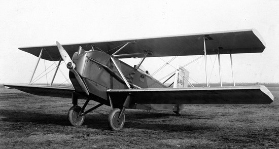
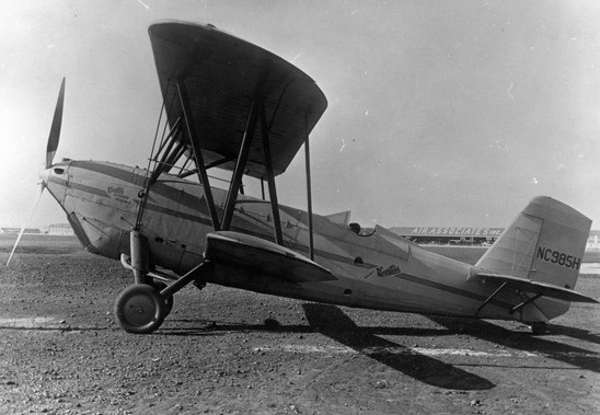
The Carrier Pigeon 2 was built by the Carrier Pigeon Co of Buffalo, New York in 1929. This was a larger and modernized version of its predecessor with a 600 hp geared Curtiss Conqueror and a three-blade prop.
Carrier Pigeon II
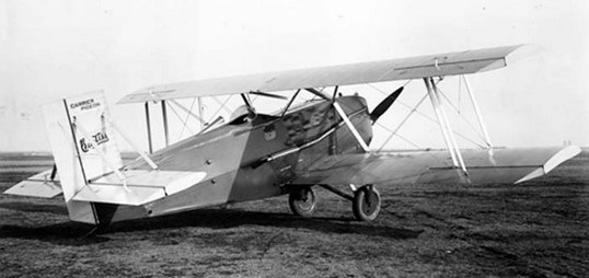
The Curtiss Lark model 41 was the follow-on aircraft, employing four interchangeable wing panels.
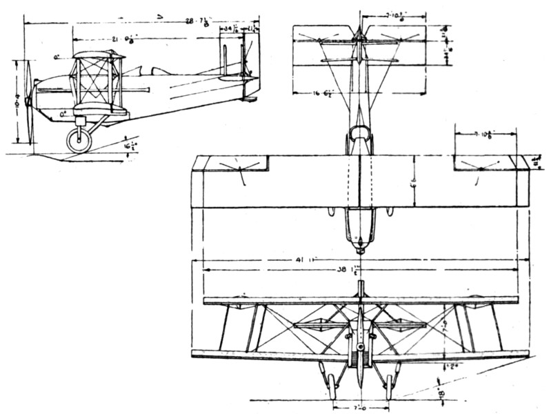
Curtiss Model 40 Carrier Pigeon I Engine: 1 × Liberty L-12, 400 hp (300 kW) Wingspan: 41 ft 11 in (12.78 m) Wing area: 505 sq ft (46.9 m2) Airfoil: U.S.A.27 Length: 28 ft 9.5 in (8.776 m) Height: 12 ft 1 in (3.68 m) Empty weight: 3,603 lb (1,634 kg) Gross weight: 4,900 lb (2,223 kg) Max takeoff weight: 5,620 lb (2,549 kg) Capacity: 1,000 lb (450 kg) cargo Maximum speed: 109 kn; 201 km/h (125 mph) Cruise speed: 91 kn; 169 km/h (105 mph) Stall speed: 43 kn; 80 km/h (50 mph) Range: 456 nmi; 845 km (525 mi) Service ceiling: 16,700 ft (5,100 m) Rate of climb: 800 ft/min (4.1 m/s) Crew: one
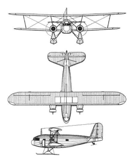
Not to be confused with the Curtiss B-2 or its 18-passenger Condor airliner development, the Condor was a 15-passenger commercial biplane airliner of the early 1930s, powered by two 529-536.5kW Cyclone radial engines. It was produced in two versions: for normal daytime flying and as a convertible day- and night-sleeper transport with six compartments, each accommodating two berths/seats.
In 1933 American Airlines began flying the 18 seat Curtis Condor, the first US sleeper plane.
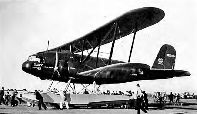
Byrd Antarctic Expidition Curtiss-Wright Condor on Edo floats
Two went to the USN as R4C in 1934 for Antarctic service. One was used on the Byrd Antarctic Expedition. They were transferred to the USMC in 1935. Two were operated as R4C-1 (9584 & 9585). Both R4C-1s were abandoned to the snowdrifts in 1941 by the US Antarctic Service, and at least one is still down there somewhere.
Air Corp Conquerer-powered Curtiss Condor
An all-cargo version was produced as the CT-32.
As a military heavy bomber with troop-carrying and ambulance capability, the Condor was supplied to China. Armament comprised five 7.62mm machine-guns and up to 1,800kg of bombs.
T-32 Condor
AT-32-C
BT-32 Crew: 2-4 Passengers: 12-24 Engine: 2 x Wright “Cycl. SR-1820-F3”, 520kW Take-off weight: 7620 kg / 16799 lb Empty weight: 5192 kg / 11446 lb Wingspan: 25.9 m / 84 ft 12 in Length: 15.0 m / 49 ft 3 in Height: 4.4 m / 14 ft 5 in Wing area: 125.5 sq.m / 1350.87 sq ft Max. Speed: 274 km/h / 170 mph Cruise speed: 235 km/h / 146 mph Ceiling: 7150 m / 23450 ft Range w/max.fuel: 2700 km / 1678 miles Range w/max.payload: 550 km / 342 miles Armament: 3 machine-guns, 1800kg of bombs