1926: Company foundation in Munich
Aviation work began in 1971 and has since built many thousands of motorgliders, lightplanes and other aircraft.
1974: Foundation of aircraft plant in Mattsies
Burkhart Grob Flugzeugbau GmbH built the Schempp-Hirth Standard Cirrus under licence during 1972-75.
Recent aircraft include the G 103 Twin III and G 109 series of gliders/motorgliders, piston-engined G 115 two-seat lightplane (some versions suited to training and aerobatics; first flown November 1985), GF 200 pusher piston-engined and pressurised 4/5-seat lightplane (first flown November 1991, turboprop-powered G-520 Egrett and Strato 1 high-altitude and long-duration research platforms capable of carrying different electronic payloads in 12 separate compartments (first flown June 1987 in G-500 Egrett form), and the most recent G-850 Strato 2C high-altitude and long-duration atmospheric/ stratospheric/ climatic research aircraft with a unique compound propulsion system using two turbocharged piston engines and two gas generators (first flown March 1995).
Inter-Wars
Grigorovich GASN / Shchetinin GASN
The bases of this project go back to an idea presented by Fleet Senior Lieutenant II Golenischev-Kutuzov, who proposed to build a special hovercraft capable of carrying out torpedo attacks on enemy ships. Little by little the idea of the hovercraft was derived from a specialized seaplane. This idea of Golenischev-Kutuzov was presented to PRTV for its implementation.
The plane began to be designed and built in 1916 at the Shchetinin Society. Co – engineered by Mikhail Mikhailovich Shishmariov, who headed the construction department at the Shchetinin factory. Shishmariov developed the entire technical project for the new aircraft, while Grigorovich was in charge only of the general conception of the model and the general direction during the preparation of the plans and technical documentation.
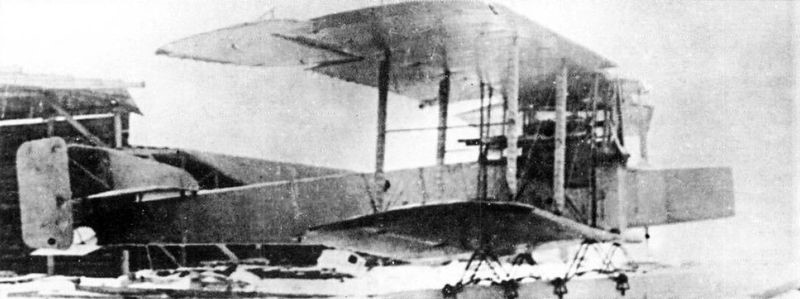
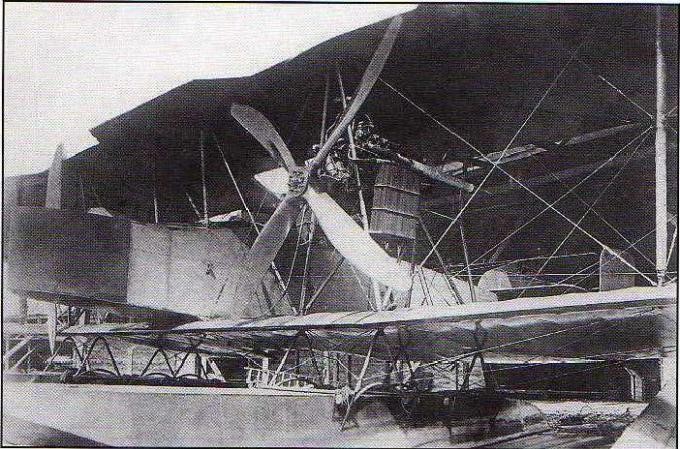
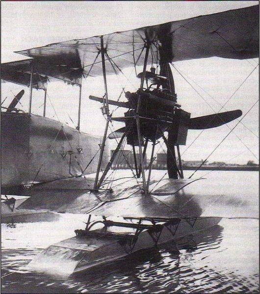
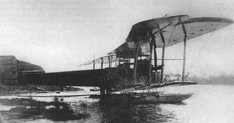
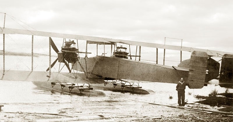
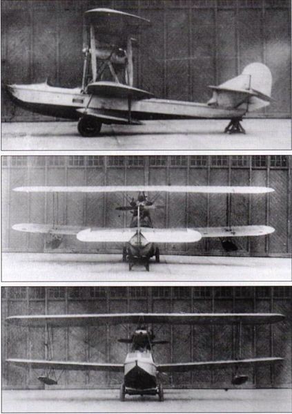
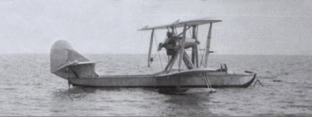
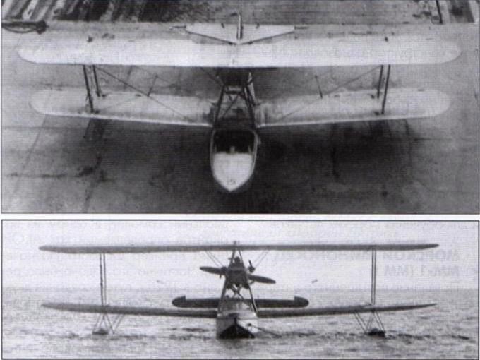
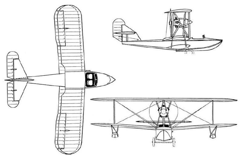
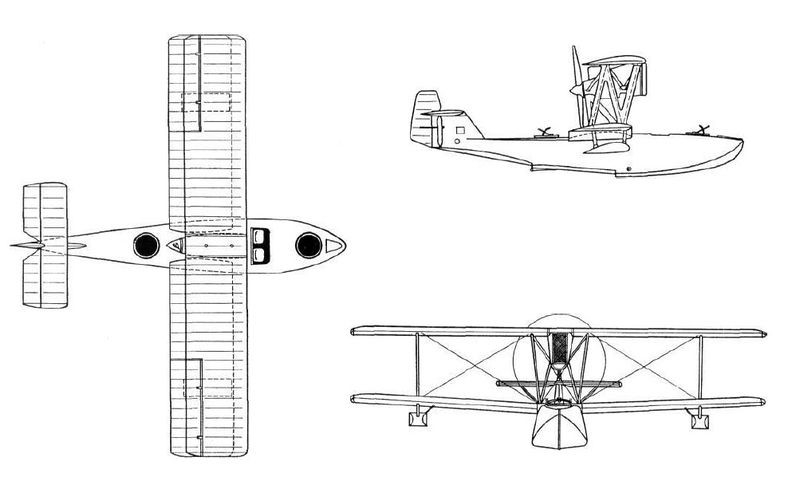
The GASN was designed as a huge twin-engine sesquiplane with a pair of floats and capable of carrying a 450-hp torpedo designed at the “Novi Lessner” factory in Petrograd. The power plant consisted of two 220 hp Renault engines located between both planes on steel tube supports and moving large four-blade propellers.
The initials GASN (Григорович/Шишмарев ГАСН) correspond to G idro Aeroplan S petsialnovo N aznachenia (Special Missions Hydroplane), although the model was also known as SON ( Samoliot O sobovo N aznachenia ) and in either of the two names it was considered to create an aircraft capable of carry and launch a naval torpedo, making this model the world’s first naval torpedo boat. We must add that this subject was considered highly secret, so in fleet documents references to the project are made as Type K.
The floats had a traditional construction similar to that used for the hull of submarines at the time and were fixed to the lower wing by means of uprights in an inverted V made of steel tubes with rubber attachment points.
The fuselage had a rectangular cross section secured by cables and covered with fabric.
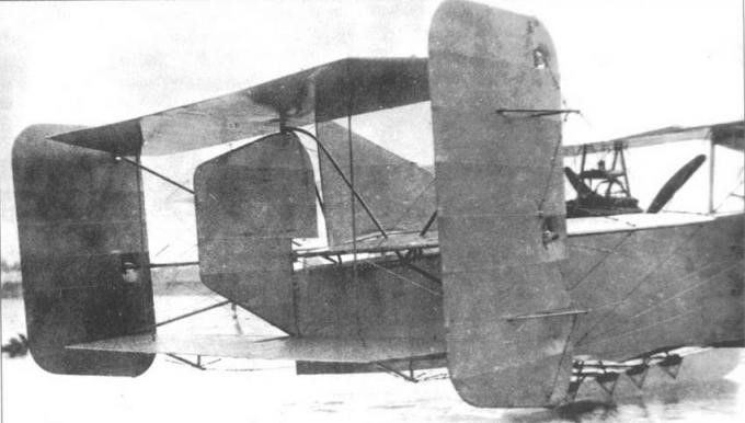
The tail was of the biplane type with three rudders and a small keel on the central empennage.
The large-span wing featured traditional wood-frame construction with fabric covering. The structure had three auxiliary spars to be able to fix the large ailerons. The shape in the plane of the wing was rectangular with a constant chord, but instead of being straight it presented a slight sagging.
The leading edge of the upper wing had indentations in the area of the propellers. The interplane supports were built with steel tubes on which they installed fabric-covered aerodynamic fairings and cable tensioners.
The GASN crew consisted of 3-4 people. In the bow area there was a position reinforced with sheets of plywood for an observer-gunner in charge of defending the forward hemisphere. Behind this position was the cockpit for two pilots and behind the wing box a third position for a gunner.
Even without completing the assembly of the first example, a request for the construction of 10 examples had been sent to Shchetinin.
The first flight of the prototype took place on August 24, 1917 in Petrograd under the leadership of Senior Lieutenant A. Ye. Gruzinov. The first tests showed that the GASN had good behaviour in the water and was easily controllable, but it was necessary to modify the trim and improve the response of the rudders. It was proposed to advance the engines, locate certain weights and increase the wing’s rake angle to advance the center of gravity of the airplane. It was also proposed to increase the surface of the rudders.
On September 24, during one of the flights, one of the floats was damaged, showing the need to reinforce its structure. After the repairs the plane began to fly again. These flights produced another series of problems, which is why the possibility of the Navy not continuing development and adapting the “Ilya Muromets” bomber or the Jioni twin-tailed plane for this role was considered.
The events of the revolution in Petrograd and the chaotic situation of the first years of the revolution prevented further development. Despite these factors, the GASN and an important set of construction elements of the started series of 10 copies were preserved intact, initially at the Shchetinin factory, which had changed its name to “Gamayún” and later at the “Krasni Liotchik” Factory.
The intention to continue the works would arrive in 1920. In that year Grigorovich traveled to Moscow and received an engineering post in Glavnoavia. His first task consisted of trying to continue the development of the projects stopped in the period 1917-1918. Grigorovich proposed to restore the work on the GASN torpedo bomber, knowing the state of conservation of the prototype and a good number of parts and components to assemble various aircraft of this type.
In November 1920 the GASN was made airworthy and the pilot LI Giks began carrying out the tests. Dmitri Pavolvich was on the shore supervising the process. On the 4th of that month, after long checks on the state of the engines, the mechanic Ozolin told Giks that the plane was ready for flight. The pilot stood in the cockpit and gave instructions to release the seaplane into the water.
During takeoff runs, tabs of fire began to come out of the exhaust pipes of one of the engines. Fearing a fire Giks decided to interrupt the test.
The engines were once more overhauled and the plane was finally cleared to take off, despite the fact that the weather conditions had deteriorated with a southerly wind that made take off difficult and the appearance of floating ice in the bay.
Steering the plane in the direction of Volni Island, Giks turned the plane upwind and took off. The plane was beginning to climb without difficulty when suddenly the engine on the right stopped working. The pilot turned for a landing near Krestovski Island. After gliding, the pilot managed to land and tried to steer the seaplane with a single engine. It was found that the seaplane’s rudder was ineffective and the aircraft only rotated around one axis. Giks directed the mechanic to go to the wing to try to compensate by sinking the float, but that didn’t help either. Waiting for help Giks switched off the engines. The plane began to drift freely.
The crew members removed the cushions from the seats, sprayed them with gasoline and lit them, throwing them near the plane as a signal for help, but help did not appear anyway.
For a whole day the plane drifted. At dawn the crew confirmed that they were about three kilometers from the shore and that the entire plane was surrounded by sheets of ice that made rescue difficult. Finally it was possible to bring the plane to the shore. The analysis of the accident showed that during the preparation of the flight, instead of oil, it was poured into the diluent tank.
With this the development came to an end.
GASN
Power plant: 2 x Renault, 220 hp
Upper plane wingspan: 28.0 m
Wing area: 150.0 m²
Length: 14.50m
Payload: 1450kg
Speed at sea level: 110-120 km/h
Accommodation: 3 – 4
Armament: two machine guns
Bombload: 450 kg torpedo or 480 kg of bombs

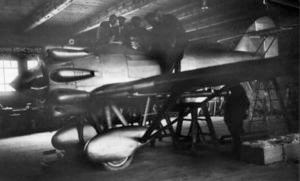
Grigorovich TB-5 / TsKB-8

In the winter of 1929-1930 the OGPU leadership decided that it would be necessary to continue the chain of success of the TsKB -39 with a new bomber. In the spring of 1930 and again with great pressure on design and construction times, the requirements were delivered.
There is a version that alleges that the initiator of this idea was the then head of the TsKB-39 Ye. S. Paufler, who, seeing a high-wing aircraft with engines under the wings in a Farman promotion, decided that he should build something like that. All the builders refused except Grigorovich, who decided to take up the challenge.
Be it this way or not, the documents confirm that in the spring of 1930 and practically without the traditional approvals, the TsKB-39 was given the task of building a heavy bomber that was named Airplane-8 or TsKB-8. The VVS however refer to the model under the designation TB-5 (Russian: Григорович ТБ-5).
The deficit in aluminum production seems consistent that the air forces had opted for the creation of a model built from more affordable materials.
By the early 1930s, a new “Sháraga” or Special Technical Bureau (OTB) of the OGPU dedicated to the development of aircraft engines had appeared in the Soviet correctional system. Noted builders such as BS Stiechkin, NR Brilling, AA Bessonov were there.
This group was given the task of designing, testing and producing a 24-cylinder engine that was known as FED (an acronym for Félix Edmúndovich Dzerzhinski). This engine with 4-row distribution in X and central injection system, had to develop a power of 1,100 – 1,250 hp at an altitude of 3,000 meters and its construction was directed by AA Bessonov. These values were considerable for the time.
The FED was conceived as the power plant for the new TB-5 bomber and its installation was planned in two variants: on the wing leading edge or in gondolas fixed to the wing intrados. Different situations led to the FED not being available at the established time, so the TB-5 had to be equipped with 4 Gnôme-Rhône 9Aq engines , a licensed copy of the excellent British Bristol Jupiter VI engine later built under license in the Zaparozhie Factory No.29 as M-22. The engines were located in tandem under each wing console. Despite the fact that the total power was almost similar to that calculated, the new drive installation had much more frontal resistance and the efficiency of the propeller was reduced by the tandem configuration, which had a negative impact on performance.
Practically all the personnel of the TsKB and a large part of the personnel of the VR Menzhinski Factory No.39 in Khodinka were mobilized for the work on TB-5, where Paufler’s “Sháraga” would be transferred from the Butirka prison.
Airplane-8 was built in just one year, which was record time for such a large and complex aircraft. Grigorovich in the same period, in parallel, worked on the IZ fighter. The appearance of both models in May 1931 (and the resounding success of the I-5) practically caused Grigorovich to receive amnesty.
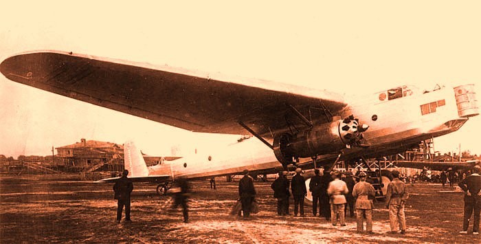
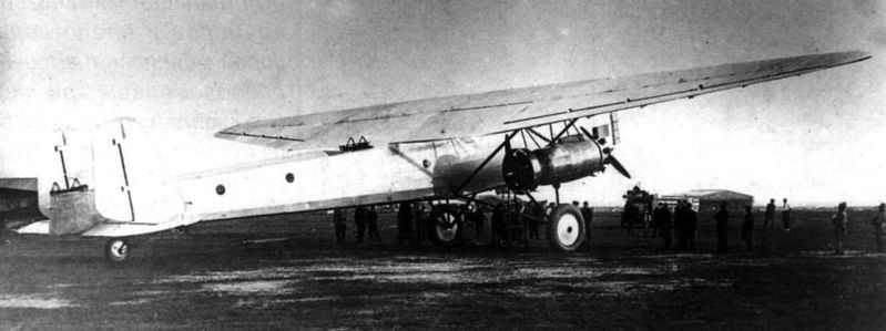
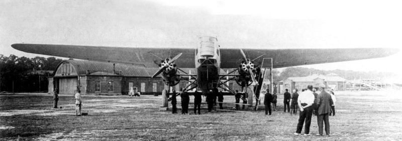
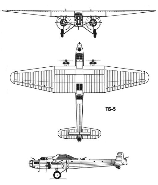
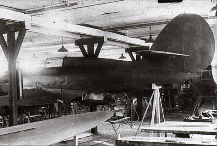
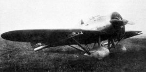
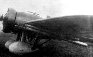
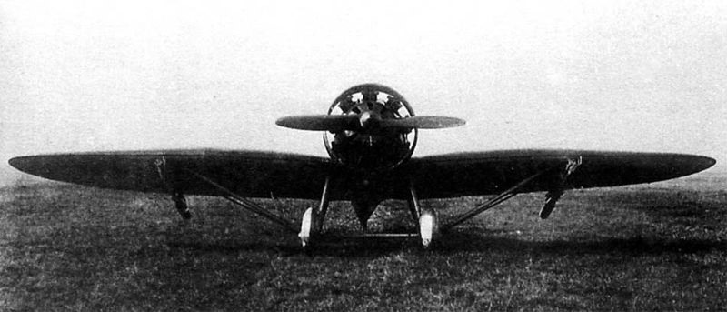
The TB-5 was designed as a high-wing bomber with a double tail unit. Its construction was mixed, with little use of aluminum, a metal short in the USSR of those years.
The spacious fuselage featured a skeletal structure constructed from fabric-covered welded steel tubes. For ground transportation, the fuselage could be divided into three sections: the forward section to the wing trailing edge, the intermediate section to the beginning of the stabilizer, and the tail section.
The TB-5 wing featured a three-spar structure and constant rib pitch. The stringers were built with special profiles made of duralumin and tubes. The ribs were formed by stamping. The construction of the wing was quite complex, especially when it came to covering the fabric.
The airfoil selected was the R-II with 18% in the midplane area and 12% in the extremes. The wing had some small bracing supports that also helped to give the necessary rigidity to the power plant.
The tail was built on the basis of a fabric-covered aluminum frame. The horizontal plane presented a second, thinner unit, located at a greater height and called “stabiliron”, creating a kind of biplane box. Its function was to decrease the force on the joystick during landing operations and trim changes.
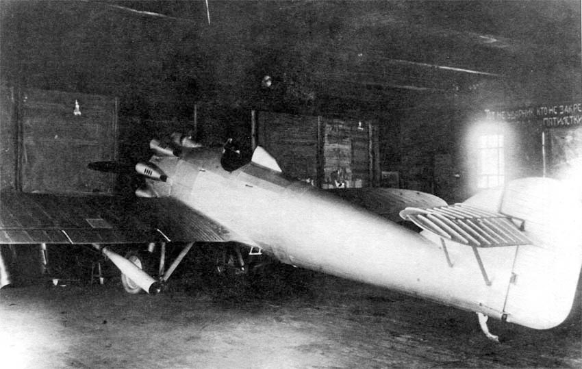
In the TB-5, on each side of the fuselage, under the wing, two 480 hp Gnôme-Rhône 9Aq engines were installed in tandem, so that they moved a propeller with two wooden blades in a driving configuration and another in a driving configuration. This engine would later be built under license under the designation M-22. In order to improve cooling, the rear engine was fitted with a Townend ring around the cylinder head.
The projected bomb load (with the use of the FED engines reached 2,500 kg) was located in an interior hold in the fuselage. DER-18 supports were located on the sides of this hold, allowing the crew to move freely inside the aircraft.
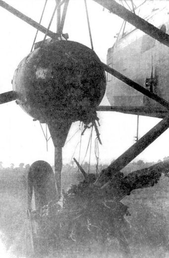
Defensive armament consisted of three TUR-5 turrets with paired Degtyaryov light machine guns for aircraft. The first of these turrets was located above the forward navigator’s position, just in front of the cockpit; the second just behind the wing and the third in the tail section of the fuselage. Apart from these positions in the bow there was a mobile firing tower, developed in the armament section under the direction of AV Nadashkievich. This can be considered the first Soviet attempt to obtain a remotely operated turret using mechanical and electrical controls.
This tower was built in the form of a cylindrical tank that rotated around its vertical axis. In the front part it had a slot that allowed the vertical displacement of the two machine guns. The horizontal movement of the machine guns was ensured by the rotation of the tower. The gunner was located inside the tower and if necessary, could leave it using a rear door towards the nose of the aircraft. For the first time in the USSR two PV-1 machine guns were installed here, built on the basis of the infantry Maxim, but using air cooling instead of water. For the first time, uninterruptible belt feeding was also used.
The rotation of the tower was carried out by means of an electrical system and the vertical movement of the machine gun was carried out by the shooter, located in a small seat.
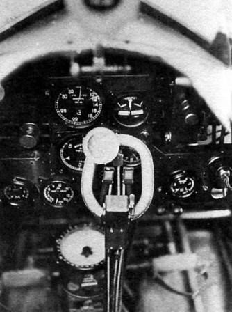
Pilot and co-pilot were located in a closed cabin, with seats side by side. The crew of the TB-5 had some facilities that could be considered a novelty for the time: a toilet and four hammocks for resting.
In the early summer of 1931 the TB-5 was first brought out onto the airfield. After engine tests and a few runs, the decision was made to allow the flight. On June 30, 1931, test pilot B. Buxgolts made the first test flight over Jodinka airfield.
After landing, Buxgolts came down from the cabin smiling and said:
- “Stability in the air is good. Ease of control excellent. Very little pressure on the rudders.”
By July 20, the plane had made four successful flights. With a weight of 11,200 kg and a fuel capacity of 1,850 kg, it had managed to cover a distance of 1,100 km during 6.7 hours of flight with an average speed of 162 km/h and a ceiling of 3,000 meters. Range with maximum fuel load of 2,410 kg and takeoff weight of 12,060 kg (including 500 kg of bombs) was 2,100 km. The maximum speed recorded was 180 km/h, the ceiling was 3,500 meters and the take-off run was about 400-420 meters.
The performance obtained was not high, especially when compared to the Tupolev TB-3 bomber that had already been flying for a few months. The main cause of these results was the powertrain. The propellers used were more suitable for a fighter than for a bomber of that size. To make matters worse the rear propeller had to be shortened so that it could operate under the wing.
Despite these difficulties, the TB-5 presented a not insignificant set of advantages, among which stood out a better distribution of defensive weapons, better distribution of the bomb load on the plane, smaller dimensions and weights, much lower cost and simpler construction. The group of builders did not lose hope of being able to count on the promised FED engines, with which performance should be increased significantly. It should be noted that by the summer of 1931, Factory No.24 had 12 engines of this type in production and had aggregates and components for another 10 units.
All these possibilities were evaluated and finally on July 25, 1931 the Labor and Defense Council (STO) asked the Pan-Soviet Aviation Union to prepare the conditions to produce six TB-5 bombers (one as a prototype of the series and the other 5 to perform military operation tests). Almost in parallel with this decision, these specimens were included in the plans for the formation of the new bomber squadrons for 1932.
The head of the VVS PI Baranov considered that, due to the delay presented by the FED engines, it was advisable to postpone the manufacture of the TB-5 copies for the year 1932 and he sent a request with these reasons to the United Council of the Economy of the USSR (VSNJ according to the initials of Vsiesoyuzni Soviet Narodnovo Jozyaistva). However, the chairman of the Council of People’s Commissars (SNK) VM Molotov had other ideas, so he ignored Baranov’s request and instead requested to take the necessary measures to speed up the construction of the series. According to M. Maslov the reasons for this decision could be of a political nature. The TB-5 bomber had been created within the OGPU and just a few days before, on July 6, 1931, this organization had given Stalin a demonstration of its achievements. There he was shown the I-5 fighter, the R-5 reconnaissance aircraft, the TSh-1 attack aircraft, the TB-5 bomber and the modern IZ gun-wielding fighter. Stalin was widely pleased and hinted that the OGPU leadership seemed to have succeeded in finding the most productive formula in aeronautical development. As a collateral consequence of this presentation, on August 27, 1931 the TsKB and the TsAGI would be unified under Czech control in the TsKB-TsAGI organization headed by Ye. S. Paufler.
During this time the TB-5 had received a significant group of improvements. In the month of June 1931, work was done on the structural reinforcement and the fixing system of the engines. The cockpits were fitted with upper access hatches, glazing was introduced in the midplane trailing edge area, the Townend ring was removed from the rear engines.
During the winter of 1931-1932 the bomber was prepared to operate with skis and several flights were made to analyze its behaviour. The design group was working on improving the conditions for installing the still awaited FED engines, but other variants of installing engines on the leading edge of the wing were analyzed. Works on this configuration were led by SA Kochierigin. Scale models with this configuration were tested in the TsAGI wind tunnel.
During this stage, other aeronautical constructors such as BI Cheranovski, VP Yatsenko and AN Refaeliants worked on the plane.
Unfortunately, the construction of the series could not be carried out, mainly because Factory No.39 was overloaded with the production of several experimental models.
The TB-5 flights continued and Soviet pilot MM Gromov would participate in them.
During one of the days of May 1932 and during a flight at a height of 800 meters a strong vibration began. The cause was that the left rear engine detached from the mounting bracket and the propeller broke the fuselage and embedded itself in a wooden bomb mock-up. The fuel caught fire.
Gromov ordered to shut off the fuel supply to the engines and began to glide with dives over the left wing to try to put out the fire. Eventually this was achieved and the pilot made a forced landing at Factory No.22 airfield in Fili. Only at this moment did they become aware that when the flames intensified the engineer AV Chesalov, who was in the wing area, had parachuted down to land without difficulty.
After this mishap, the TB-5 remained in Fili until December, without repairs being attempted. Grigorovich had switched to the development of fighters.
At the end of 1932, after verifying that the manufacture of the Túpolev TB-J bomber (military version of the ANT-14) was even more complicated than those of the TB-3, it was decided to return to the subject of the TB-5.
To assess the possibility of re-establishing the TB-5, a commission was created led by the representative of the TsAGI VN Chernishevich, who worked on December 1, 1932. As expected, the competing aircraft was harshly criticized: the aircraft was valued as overweight, with poor motor installation and design problems. On the other hand, the TB-5 had had its engines, part of the flight instruments, and weapons disassembled, and it was estimated that to give the bomber full flight capacity again, it would be necessary to invest 75 or 100 thousand rubles.
The commission considered that to improve the bomber it would be necessary to reinstall the engines on the wings, which would guarantee an increase in speed, which would reach 190-200 km and a ceiling of 4000 m, but the cost of the modifications would amount to 200 thousand rubles.
Incredibly, despite these assessments, it was decided to restore it with the proposed modifications, for which it would be returned to Factory No.39. A short time later, at a meeting of the VVS management, it was recognized that even with the modifications, the benefits of the TB-5 did not satisfy the requirements of the moment.
In the month of February 1933 the head of the GUAP Baranov instructed:
- “The plane disarm it. Works on him stop them.”
With this it all ended. TB-5 was not restored and its remains were handed over to the TsAGI structural resistance department. The Tupolev TB-J also did not see the light of day, as by the end of 1933 the specifications for bombers had grown considerably.
On the basis of the TB-5 in 1931 Chertverikov developed the reconnaissance flying boat MDR-3 or TsKB-11, which kept the design of the wing, tail and structural elements of the bomber. Finally, this design would not be produced either.
TB-5
Powerplant: 2 × 480 hp M-22 ( Bristol Jupiter VI
Wingspan: 31.00m
Wing area: 150.00 m²
Length: 22.10m
Height: 5.02m
Empty weight: 7483 kg
Normal takeoff weight: 12535 kg
Wing loading: 83.5 kg/ m²
Power Load: 7.0kg/hp
Fuel + lubricant capacity: 3300 kg
Top speed: 200km/h
Cruising speed: 182km/h
Range: 2100 km
Ceiling: 3500 m
Accommodation: 5 – 7
Armament: 3 x TUR-5 type turrets with paired Degtyaryov light machine guns / 1 x pair of PV-1 machine guns
Bombload: 1000 kg
Grigorovich MUR-2
By 1929, the TsAGI in Sevastopol researchers began to develop experiments with a view to defining the ideal characteristics of the hulls of ships and aircraft.
Between 1929 and 1930 the engineer NN Podsevalov began to experiment with the different pressures experienced by the hull of a flying boat in the different regimes of navigation; take-off and landing. For this, a series of membranes fixed to dynamometers were installed in different positions at the bottom of the hull of the Grigorovich MUR-1 prototype.
For the continuation of the tests, Grigorovich was asked to build a slightly different hull with a 14º increase in the angle of incidence in the keel area. Built by GAZ No.3 “Krasni Liotchik” from Leningrad, this new flying boat model received the name MUR-2 (Russian: Григорович МУР-2) and was tested in flight, showing characteristics similar to those of the MUR-1. Later it was delivered to the TsAGI for further testing, so this model, of which only one example was built, can be considered purely experimental.
The hydrodynamic tests continued until 1931 allowed the TsAGI to issue the Stiffness Norms for the design of flying boats.
Grigorovich MU-2
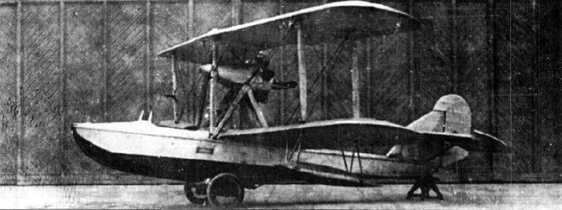
Attempts to modernize the M-5 flying boat gave no improvement and the objective could only be achieved through a totally new construction. Grigorovich decided to take on the task. The new design would see the light as MU-2 (Russian: Григорович МУ-2) or Morskoi Uchebni – 2 (Naval Trainer).
For the MU-2 Grigorovich selected the 100 hp Soviet M-11 engine. The hull was built entirely of metal and featured a new deck design with straight contours and an angular groove, which should give it good seaworthy characteristics, apart from being easier for production. The structure of the MU-2 contained 27 frames, of which 5 constituted the supports for the watertight compartments of the hull.
The wooden wing had a double spar structure with an Eifel-367 profile. The interplane uprights were also made of wood. Ailerons were on both planes.
The structure of the tail was made of duralumin, covered with fabric.
The shrouded M-11 radial engine sat on a pyramidal structure of metal tubes and drove a pusher propeller. The main fuel tank, with a capacity of 105 liters, was located in the hull, behind the cockpit. An auxiliary tank for direct supply to the engine, with a capacity of 11 litres, was located in front of it, protected by the elongation of the cabin. The transfer of fuel from the main to the auxiliary tank was carried out by a compressor or a manual reserve pump.
The MU-2 flying boat featured an open cockpit with a windshield for its two crew members sitting side by side. The control was by lever and the instrumentation was duplicated. The pilots’ pedals were synchronized.
Construction of the MU-2 began in 1927 at GAZ No.3 “Krasni Liotchik” from Leningrad and was completed without the presence of Grigorovich, who was in prison at the time.
During the construction process it was found that the MU-2 would be 150-200 kg heavier than the calculated values. The empty weight reached 820 kg, of which 220 corresponded to the hull. This was because the dimensions of the hull remained generally similar to those of the M-5, when according to the regulations, taking into account its metallic construction, they allowed a 10% decrease in size. Although the construction was quite careful, it was impossible to maintain the 660 – 700 kg of the project.
The tests of the flying boat began on August 29, 1929 at the testing station of Factory No.31 in Taganrog with the naval pilot ST Rybalchuk as responsible.
On September 6, 1929 the future of the MU-2 was discussed during a meeting of the Technical Committee of the Aviatrust. The most renowned shipbuilders of the time were present at this activity: Richard, Artamonov, Zhuravchenko, Samsonov, Chetverikov and Polikarpov.
MU-2 was reported to be at Taganrog, where the pilot Rybalchuk had executed the first flight. Preliminary results showed that the cabin was narrow, but the access hole was very wide. The flying characteristics of the flying boat were assessed by the pilot as rather poor and he also stated that the plane would not be able to get out of a spin. The climb did not stand out either, since the MU-2 reached 3,500 meters after 85 minutes of flight. The take-off run was quite long.
It was further noted that the centering of the MU-2 was similar to that of the Italian model Savoia S-16, located at 38% of the length, so it was proposed to carry out tests in the wind tunnel of the TsAGI and then proceed to improve the apparatus.
In practice nobody did anything to improve the MU-2. Shortly after, using this design as a basis, the builder of Factory No.23, A. S. Moscaliov, would present his project for a wooden-hulled training flying boat that would receive the name MU-3. This model was built during 1931 and later successfully tested, but would not go into series production as it was displaced by the Shavrov Sh-2.
Powerplant: 1 × 100 hp М-11
Wingspan: 11.80m
Wing area: 35.60 m²
Length: 8.60m
Empty weight: 820kg
Normal takeoff weight: 1086 kg
Fuel weight: 90kg
Maximum load capacity: 266 kg
Wing loading: 30.5 kg/m²
Power Load: 10.9kg/hp
Maximum speed at sea level: 136 km/h
Cruising speed: 108km/h
Landing speed: 70km/h
Practical range: 380 km
Endurance: 3 hours
Practical ceiling: 3150 m
Time to 1000m: 10.8min
Time to 2000m: 26min
Time to 3000m: 53min
Turn time: 18 sec
Take-off run time: 35 sec
Landing run time: 12 sec
Accommodation: 2
Grigorovich MRL-1 / MR-1
At the beginning of 1924, a request was received from the Navy leadership to create a new naval reconnaissance flying boat. The technical task, delivered by the VVS Aviation Supply Department on June 13, specified the use of a Liberty engine, which is why the model was called MRL (Russian: Григорович МРЛ-1), after the acronym for Morskoi Razvietchiks motorom Liberty). although it has sometimes been named simply MR-1. In order to carry out this project, the development of an all-metal fighter was cancelled and 10,000 rubles were transferred to Grigorovich.
Work began in Moscow, but the development was moved together with the Grigorovich group to Leningrad.
Concept drawings, plans, and calculations were developed by engineers Piotr Dmitievich Samsonov and Kiril Alexandrovich Vigand. Since DP Grigorovich had left Factory No.1, design work was carried out in his apartment on Sadovo-Kudrinskaya Street. Work on the project began in June, and by September 18, 1924, it was submitted for evaluation. After reviewing all the documentation and verifying the coincidence of the requested benefits with the calculations, the Technical Scientific Committee of the Air Fleet approved the project. Shortly after, the instruction was issued to build the prototype of the flying boat at Factory No.3 “Krasni Liotchik” in Leningrad.
The MRL was designed as a four-seater biplane flying boat with a 400 hp Liberty engine driving a pusher propeller. The model had clean lines but it was very heavy.
The wings, with a Gottingen 436 profile, were rectangular in plan, with ailerons on the trailing edge of both wings. The upper wing was completely straight in its frontal view, but the lower plane had a certain positive dihedral and some small fixed stabilization floats were fitted. The interplane uprights were N-shaped with aerodynamic wood cladding and the necessary tension was achieved by means of cables.
The double-reinforced hull was very heavy and labor-intensive and expensive to build. With a total length of 9.8 meters and 4 meters to the first step, the width reached 1.5 meters and the maximum height 1.3 meters. The entire plywood hull was covered using 4 x 80 mm strips made from different types of wood and fixed using copper rivets with aluminum washers. The deck and the upper part of the rails were covered with pine wood boards, a little further down the rails were made of ash and walnut and from the waterline to the bottom of mahogany, which in this last area was installed with double layer. Between the plywood and the board covering, a layer of fabric coated with a waterproof lacquer was installed.
The tail was of the monoplane type with the stabilizers installed on a short keel and braced by simple struts. The keel ended in a small rudder. The rectangular stabilizer could change its angle of incidence in flight.
The engine was installed on mounts in the center of the biplane wingbox and featured a cooling radiator located at the front.
The MRL-1 was designed for three crew members. Pilot and co-pilot sat side by side in an open cockpit, protected by a windshield. At the bow was a facility for a gunner operating a machine gun located on a ring mount. A second defensive post was located behind the power plant and was intended to defend the rear hemisphere.
The construction of the MRL-1 was completed at GAZ No.3 in Leningrad in May 1925. On June 6, the model was transferred to the naval base where it was assembled, adjusted and the first operations of entering the water were carried out.
From the first stage of the tests it was possible to verify that the front radiator was very small, so the necessary cooling of the engine was not achieved. The propeller was calculated for 1,700 revolutions/minute, but the engine at full capacity only guaranteed 1,550.
The first flight was made on June 2, 1925. After carrying out some test flights, it was concluded that in operations on water the model presented poor longitudinal stability and the take-off run was too long.
In the air the model behaved normally and was easily controllable. The maximum speed reached during the tests was 180 – 185 km/h at an altitude of 1000 meters.
During one of the last test flights, the oil tank burst and the aircraft was forced to make an emergency landing with the engine stopped. The cause of the explosion was the absence of an exhaust valve in the tank, which caused the oil to heat up and the pressure of the air accumulated there to increase, causing it to burst through the seam of the welds.
The tests included only 9 flights and were generally considered positive, since the model met the requested specifications, but the long take-off run and the problems when separating from the water were considered intolerable, so it was recommended to modify the design of the contours of the hull.
The ascent rate and the ceiling reached of only 3,050 meters were also noted as unsatisfactory.
Although the decision had been made to mass-produce the model, the request was eventually withdrawn. The only example built was delivered to the White Sea for exploitation, being used in the Solovietski Special Operations Camp (SLON) as a link with the mainland.
MRL-1
Powerplant: 1 x 400 hp Liberty
Wingspan: 13.2m
Wing area: 50.0 m²
Length: 10.6m
Empty weight: 1660 kg
Maximum takeoff weight: 2600 kg
Fuel weight: 520kg
Full load capacity: 940kg
Wing loading: 52.0 kg/m²
Power load: 6.5kg/hp
Maximum speed at sea level: 185 km/h
Landing speed: 95km/h
Practical ceiling: 3050 m
Endurance: 5 hours
Range: 950km
Turn Time: 65s
Climb to 1000m: 11min
Climb to 2000m: 26min
Climb to 3000m: 55min
Take off time: 40s
Landing time: 15s
Accommodation: 4
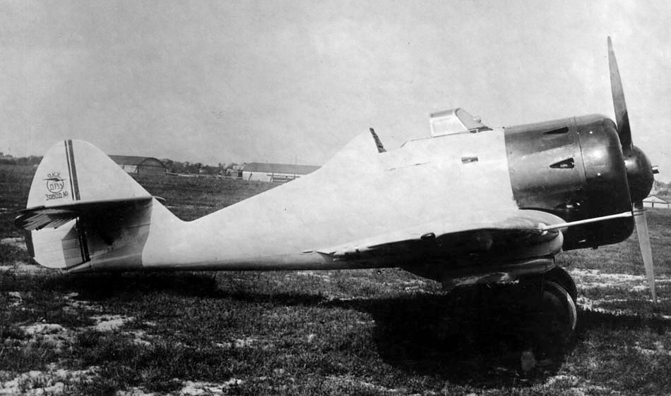
Grigorovich IP-2 / DG-54
Grigorovich designed the IP-2 / DG-54 (Russian: Григорович ИП-2 (ДГ-54)) fighter in the winter of 1935-1936. The IP-2 appeared as a modification of the IP-1 gunship fighter and as main differences it had slightly increased dimensions and a 760 hp Hispano-Suiza 12Ybrs engine. The manufacturing name of the model was DG-54 and in some literature it has been called PI-2 by the acronym P uchechni I sterbitiel or Gunship fighter.
The IP-2 fighter was designed as a single-seater monoplane with a low cantilever wing. In plan view it was similar to the British Supermarine Spitfire.
The IP-2 kept the elliptical wing introduced in the IP-1 and built according to the “Grigorovich wing without stringers” formula. The main difference is that in the case of the IP-2, the builders were forced to install an inverted gull-type wing in order to raise the nose of the device from the ground in the presence of a larger diameter propeller.
The fuselage in this case maintained a construction similar to that of the IP-1, but it featured an elongated nose in order to accommodate the Klimov M-100A engine, a licensed version of the 860 hp Hispano-Suiza 12Ycrs. The tailplanes, elliptical in shape, presented in this version medium implantation and cantilever.
The landing gear maintained the retracting system with the wheels semi-inserted in specially designed fairings and installed at the wing angle change point.
Another new detail in the IP-2 was the closed cockpit for the pilot. This fighter incorporated a powerful armament consisting of a 20 mm ShVAK cannon located in the V of the engine and 4 ShKAS 7.62 mm machine guns located in the wings. This could be increased up to 10 machine guns in the ground attack version. Under the wing, supports were provided to carry up to 40 kg of bombs.
During the first half of 1936 a full-size mock-up was built at Factory No.1 “Aviajim” followed by approval to build an experimental prototype.
The project was completed and in the first half of 1936 a set of parts and components had already been produced, but once again Grigorovich was affected by the restructuring of the Soviet aircraft industry. On May 11, 1936, the Labor and Defense Council (STO) decreed the specialization of aeronautical factories and the linking of builders with the serial production of their models.
In the summer of 1936 Grigorovich’s OKB was closed and he transferred to GUAP as head of the naval department. His group, made up of 25-30 people, was sent to the TsAGI Experimental Construction Factory (ZOK). All the unfinished projects ended up there, including the IP-2 fighter. The ZOK had been intended to specialize in the development of scout aircraft, so all documentation and items produced were sent to Kharkiv Factory No.135, where the IP-1 was produced. A year and a half later, when the production program was redefined for 1936 –1937 the IP-2 was excluded.
Powerplant: 1 × 860 hp Klimov M-100A
Wingspan: 11.00m
Wing area: 20.60 m²
Length: 8.06m
Height: 3.27m
Empty weight: 1430 kg
Take off weight: 1952kg
Wing loading: 94.75 kg/m²
Power load: 2.27 kg/hp
Accommodation: 1

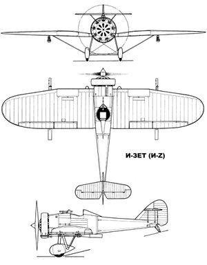
Grigorovich IZ / TsKB-7
At the end of the 1920s work related to the development of a new type of barrel known as a dynamoreactive barrel (DRP) and characterized by the absence of recoil.
Grigorovich IZ / TsKB-7 Article
Great attention was devoted to the development of the 76.2 mm aviation guns. The main reason for this decision was the need to increase the firepower of the fighters, whose machine guns proved ineffective against the new all-metal bombers.
The first gun of this type, called APK-1 after the acronym for Avtomaticheskaya Pushka Kurchevskovo or Kurchevski ‘s Automatic Cannon, began tests on July 26, 1929. It became clear that the use of APK guns required the design of new types of aircraft with great structural reinforcement.
The task of designing this new type of aircraft was assigned in parallel to the TsAGI led by AN Tupolev and the TsKB under the direction of the OGPU, headed (unofficially) by DP Grigorovich as technical director.
Grigorovich had been under arrest since September 1928 and was under the supervision of the OGPU. After the collective of prisoners under his leadership succeeded in developing the excellent I-5 fighter in the spring of 1930, Grigorovich, though still under arrest, was appointed chief consultant to the TsKB. Prison conditions for him were improved, even allowing him to travel with his family on vacation to Yalta (with the necessary company of OGPU staff). Returning from the south, Grigorovich was asked to develop a fighter aircraft with three-inch barrels.Kurchevsky.
The aeronautical development system applied in the TsKB-39 did not conceive the existence of a main constructor. The designs were developed by brigades directed by a specialist and from the initial conception, different departments were in charge of carrying out the work related to their specialty. For this reason, the models developed in the TsKB during this period are generally not referenced to a specific author (generally in the literature they are named TsKB and the particular name of the model). However, in the case of the IZ fighter, the same is not the case. Despite being built within the structure of the TsKB, the task was so secret and a priority that Grigorovich received the approval to form a small group under his direction, which was to be in charge of all the development of the model.
The new task force of the Grigorovich began work in one of the hangars of Factory No.39. Among its members were: AN Sidielnikov, VL Korvin-Kerber, AN Nadashkievich, Ye. I. Mayiranov, VD Yarovidski, G. Ye. Chupiloko and S. N. Shishkin. In general, this group had stood out during the development of the I-5 fighter , so many of the construction elements of the new fighter would be designed under this influence.
In relation to the origin of the name for the new fighter there are several versions. The first version establishes that due to the secrecy in relation to the project, it was decided to name it using the Latin letter Z (something unconventional since letters of the Cyrillic alphabet were generally used for these cases). In this way the name of the fighter combines the Cyrillic letter И (corresponding to the I and acronym for Istrebitiel or hunting) with the Latin letter Z.
Other sources state that since the fighter was developed in hangar No.7 of Factory No.39 its initial name was I-7, but due to the appearance of another model I-7 mass-produced in Factory No.1 from Moscow (licensed version of the Heinkel HD-37), Grigorovich suggested adding a line at the bottom of the number so as not to have to redo all the documentation and thus the 7 became Z (Russian: Григорович И-Z – ЦКБ-7).
Which of these versions is the real one is difficult to establish. In period documents the fighter is referenced as TsKB7, TsKB-7, Z(N-7). Only a couple of years later, when the model had already been approved, the term И-Z began to be used in the documentation, but due to the fact that most typewriters in the USSR lacked the possibility of writing Latin letters generally everything was written in Russian as И-ЗЕТ (I-ZET).
By the spring of 1931 Grigorovich’s work had attracted widespread attention. Members of the GPU leadership and later from the Kremlin would soon begin visiting the TsKB. The TsKB would be visited by Molotov, Ordzhonikidze, Andreyev, Voroshilov. As a result of this interest, most of the prisoners would soon be released.
In May 1931 the newspaper “Pravda” would publish “granting amnesty to the builders listed below, previously accused and sentenced by the OGPU college to different sentences of a social nature and at the same time rewarding them. To the chief builder of experimental models Grigorovich, Dmitri Pavlovich, retracting his previous positions and proving after a year’s work of his sincerity – the recognition of the TsIK USSR and a cash prize of 10,000 rubles.”
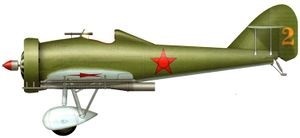
The IZ fighter was designed as a single-seat, low-wing braced monoplane. The fuselage featured metal construction. The entire front and center fuselage was made of a skeleton of welded chrome-molybdenum steel tubes. In general, this entire forward section presented little difference from that of the I-5 fighter. The tail section was all new, semi-monocoque construction and attached to the front at four points.
The structure of the tail section was made up of 11 elliptical frames, of which the last four were integrated into the keel. The fuselage featured a duralumin coating.
The wing had a double spar structure and its fixing was reinforced o by a pair of steel supports with a drop-shaped section. The wing construction in the prototype was developed using stainless steel (Enerzh-7) joined by welding, but the production examples used wooden wing structure. The stringers had a box-like structure to which 22 plywood ribs were attached. The wing covering was made of fabric, except for the area where the cannons were fixed, where it was reinforced with aluminium.
The wing profile was Gettingen 436, but its thickness decreased in the area where it joined the fuselage. The centroplane had a rectangular shape, but the wing consoles, in order to reduce the inductive resistance, received an elliptical shape.
The tail unit was duralumin and heavily reinforced. The entire empennage skin, excluding the leading edge of the keel, was corrugated. The stabilizer was raised on the empennage in order to avoid the harmful effects of exhaust gases from the guns and was braced to the empennage by two parallel metal studs. Initially, the rudder had a fabric covering, which was soon replaced by a duralumin one.
The landing gear featured steel N-legs with rubber cushioning and a central axle linking the 750 x 125mm main wheels. Tensioning straps started from the undercarriage to the wing. In the tail a steerable skate with rubber cushioning.
The power plant of the IZ consisted of the M-22 engine (version of the Gnôme-Rhône 9Aq, a licensed copy of the British Bristol Jupiter VI engine built in the USSR at Zaparozhie Factory No.29) and its installation it was virtually identical to that of the I-5 fighter, built by Polikarpov and Grigorovich some time before. The cylinder heads on the prototype featured individual fairings, which were replaced on production models by a Townend ring.
The pilot was located in an open cockpit, located behind the engine and lacking a windshield.
The armament consisted of a 7.62 mm PV-1 machine gun located in the fuselage, to the right and in front of the pilot, which was used as a sighting rifle for the cannons. This machine gun was fitted with a PUL-9 synchronization system to allow firing through the moving propeller. Under the wings were the two APK-4 or APK-4bis cannons.of 76.2mm. Its installation on the wing allowed firing without interference from the propeller. In the first IZ the guns were located in the inner area of insertion of the wing supports. Later the guns would be moved further out on the wing. Each barrel was equipped with a cylindrical magazine with 6 shells and a seventh already mounted on the gun and featured an automatic reloading system from the use of exhaust gases. 0.6 m cylinders designed as exhausts were located at the rear of the guns.
The IZ prototype was ready for the summer of 1931. The date of its first flight is not known with certainty, but it is known that it was made in this period by test pilot Benedict L. Buxgolts.
On July 6, 1931 Factory no.39 was visited by Stalin, who had previously been informed about the IZ fighter. Stalin not only checked the plane, but climbed into the cockpit and moved the flight controls. The main builder was not there at that time, so the presentation of the model was made by the head of the TsKB for the GPU Ye. S. Paufler.
During this visit Stalin was presented with other models developed at the TsKB such as the I-5 fighter in various variants, the TB-5 heavy bomber, the TSh-1 attack aircraft and TSh-2, modifications of the R-5. Stalin was favorably impressed. As a result, by the Aviation Union Order No.265 (VAO according to the acronym of B ciesoyuznoye A viatsionnoye O biedinienie) of August 27, 1931 the TsKB and the TsAGI would be united into a single organization (known generally as TsKB-TsAGI), under the direction of Paufler.
The IZ had been built in a hurry and this was reflected in its initial results. Grigorovich’s collective was forced to work on improving the model for a year. Despite successful tests, Kurchevski’s guns generated constant headaches. Building and testing the single-shot APK-1 cannons proved to be an extremely simple task compared with the development of autocannons capable of self-reloading and multiple shots.

This situation began to worry some personalities. During a meeting at Factory No.39 held on March 2, 1932, the head of the VVS RKKA PI Baranov stated:
- “The Z(N-7) aircraft has been built for almost a year, Factory No.39 presented it to the government in June-July 1931 and promised to improve it. where is the result?
Paufler replied that the plane had been ready for a long time, that 74 shots had been fired from the guns on the ground and 10-12 in the air, during which the exhaust of one of the APK guns had been damaged, but in general everything was fine. well and the factory was ready for series production. Kurchevski, who was present, complained that he was not allowed access to the plane to work.
It was established that the Z(N-7) would be used as an interceptor aircraft, designed to destroy enemy bombing forces in frontal encounters. Impact 3 kg shells with an initial velocity of 347 m/s were expected to make a formidable weapon. It was decided to submit the Z(N-7) for state testing on March 12.
After the first prototype, a second improved specimen would appear, which in some literature has been called I-Zbis. This model would fly for the first time in 1932.
No evidence has been found to show that the acceptance tests were carried out by the military, but on April 27, 1932, the director of Factory no.39 S. Margolin signed an agreement with the VVS Directorate to build 20 “Z” fighters with special weapons worth 77594 rubles per unit. Taking into account unforeseen expenses until September 1, 1933 (fixed delivery date) Factory No.39 would receive 2,398,909 rubles, which brought the actual price of each aircraft to 119,945 rubles.
This series were intended to carry out field tests and develop the tactics of use of the cannons and differed from the prototype by the use of a wooden wing and an M-22 engine faired with a Townend ring.
Between 1934 and 1935, another 50 aircraft were built at the Kharkov Factory No.135, but their flight characteristics and performance were not very good; moreover, the APK guns were also unconvincing. The maximum speed in these aircraft was about 40 km/h lower than that of the prototypes. Most of these ended up being used in different test programs.
One of the first serial specimens, the IZ with number 39009, was tested in February – March 1933 at the VVS polygon in Mónino. The tests were carried out by test pilot Yu Piontkovski.
The aircraft carried a working cannon under the left wing and a mock-up of similar weight and dimensions under the right. For the development of ground tests in Shelkovo. This land had recently been handed over to the NII VVS and there were no buildings of any kind on it. There, a structure 5-6 meters high was prepared with an inclined ramp from which the shots were fired. During these tests, intended to check the resistance of the aircraft during the action of the gun, no problems were found.
From September 14 to October 1, 1933 in Shelkovo the tests of the IZ 39010 were carried out, armed with the APK-4 serial guns equipped with magazines for 6 projectiles (plus one directly located in the barrel).
The flights were carried out by M. Stselnikov and in total they lasted 16 hours and 20 minutes.
The results highlighted that 39010 was built quite similarly to the prototype and due to its dimensions and characteristics, no differences were observed.
The cockpit was comfortable and spacious. During takeoff the IZ lifted off the ground with ease and horizontal flight was performed with the stick fully free. Stability was good at all speeds and control was smooth and easy.
The data obtained for time of ascent to 5,000 m (14 minutes) and flight ceiling (7,000 m) were considered acceptable, but the maximum speed of 259 km/h and the range of 310 km were evaluated as poor. The main cause of these difficulties was defined as the inefficient landing gear and the great aerodynamic resistance of the APK guns.
The artillery armament passed the tests, but its shell capacity was considered too small. Kurchevski proposed to install a magazine with 10-14 shells in the wing, but this would not come to fruition.
As a conclusion, it was defined that the IZ fighter could be received into service with the RKKA VVS with the fulfillment of the following conditions:
Raise top speed to 300 km/h
Increase fuel capacity
Raise the amount of shells to 20 units
Install electrical equipment and radio
Desire to increase the structural rigidity of the plane, because after 300 – 500 shots it was necessary to carry out a complex maintenance intervention on the aircraft. The VVS wanted to raise this number to 1,000 shots.
The modified aircraft was to be ready by March 1, 1934.
The installation of the cannons added a significant number to the aircraft’s weight. The two APK-4 guns weighed about 150 kg, and the 14 ammunition – 55 kg. This meant 12% of the model’s takeoff weight. The APK-4 dynamoreactive cannons were installed in the wing of the aircraft with angles of 2 – 3º. All this part of the wing was coated with duralumin. This location contributed significantly to the poor performance due to the high aerodynamic resistance of the installation.
In April 1935, a special aviation group was created, consisting of a squadron of IZ fighters, one of R-5 reconnaissance aircraft for cone towing, and a TB-1 bomber. This unit was transferred to Yevpatoria in order to test the behavior of the gun in the air, its influence on the construction of the IZ fighter and the definition of its service time.
Test flights began on May 15, 1935. The tactics provided for firing in a dive, ascent or horizontal flight, both in individual salvos and in series.
It was found that after 100 to 150 shots the aircraft had to be inspected in depth as it generally suffered extensive damage to its structure and coating, making it necessary to replace the damaged elements and components. Fundamentally, the rivets, joints and coating suffered. It was also established that each cannon could withstand about 240 shots.
Cases are recorded of number 13534, which was capable of withstanding just over 340 shots without the need for repair. From the results of the tests it was considered that the period of active service of the IZ model should be defined by the scope of the figure of 400 shots.
In the development of multiple tests, most of the IZ specimens produced became unusable. At the beginning of 1936 the units received only a few copies. By that time the work on the DRP guns had practically been abandoned and the use of these fighters was out of date. For this reason the IZ did not get to operate in the designed roles.
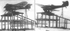
The IZ was one of the aircraft used by VS Vaxmistrov in the development of his combined or ”Zvenó” aircraft. From the beginning of 1931 Vaxmistrov began work on the suspension of an IZ fighter under a Tupolev TB-3 bomber. In 1934 Vaxmistrov decided to develop a new version of the Zvenó by combining a TB-3 with two IZ fighters. this combination would be known as Zvenó-3 or 3-3.

In this combination the fighters were fixed on the ground by special supports to the wing of the bomber. Before release, these supports separated from the wing by 0.5 meters in order to avoid impacts of the empennage against the wing at the time of detachment.
The first flight of this combination was made in July 1934. The TB-3 bomber crew was led by PM Stefanovski and the IZ fighters included AV Korotkov and Grodz. During the release Korotkov’s fighter rose, breaking the bomber’s wing skin and getting stuck in it. An emergency landing was necessary. Luckily, at the time of landing, the plane broke free as a result of the impact with the ground. The fighter pilot was killed but the rest of the crew managed to save themselves. As a result the Zvenó-3 combination was abandoned.
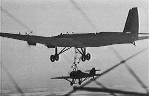
The next variant of use of the IZ fighter in combined aircraft was known as Zvenó-5 (3-5) and involved suspension of an IZ fighter under the TB-3 bomber once it was in the air. The mother plane released a kind of trapeze that was fixed to the DER-15 rear supports. The release of this structure was carried out by the on-board mechanic from its location and its subsequent retraction was carried out with the help of a crank.
The IZ fighter was also modified. In the upper part of the fuselage a fixing structure with a security system was installed. The wing consoles were also reinforced, since the section of the wing ribs 12 – 14 ended up resting on the bomber wheels once the trapeze was retracted. The other support point was at the top, behind the cockpit.
Testing of the Zvenó-5 began on March 15, 1935. In this case, the IZ was piloted by VA Stepanchonok, while PM Stefanovski was once again at the controls of the TB-3. Initially, training flights were carried out consisting of placing the fighter behind the bomber, equalizing their speeds at about 140 km/h and then making approaches and separations to a percale tape fixed to the bomber. Until March 21, 25 trainings of this type were carried out.
The world’s first capture of one aircraft in flight by another took place on March 23, 1935. After fixation the IZ was elevated. The Zvenó dropped to a height of 500 meters and flew over the aerodrome where a VVS commission sent to supervise the test was located. After recovering the 1200 meters of height, the separation took place, again without problem. Until March 29, 5 flights like this were carried out with capture and release of the IZ fighter in the air.
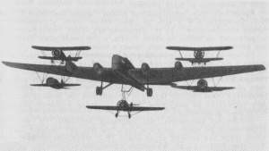
By the fall of 1935 Vaxmistrov prepared for tests a new combined system known as Zvenó TB-3 4M-17 + 2 I-5 + 2 I-16 + IZ. Vaxmistrov himself named this creation Zvenó Aviamatka PVO (AM). On the ground under the wing of the TB-3 two I-16 fighters were fixed and on the wing the two I-5 fighters. The last member, the IZ fighter, was fixed once the Zvenó was in the air.
During the tests the TB-3 was flown by PM Stefanovski, the I-5s by AI Nikashin and SL Suprún, the I-16s by TT Altynov and KK Budakov and the IZ VA Stepanchonok.
The experiments demonstrated the feasibility of using the chain consisting of one bomber and five fighters. Never before or since in the world has anything like it been tried. The tests were carried out jointly with the Moscow Factory No.22, in charge of carrying out the modifications to the fighters and the mother plane.
The conclusions of the tests determined that the Zvenó with TB-3 4M-17 + 2 I-5 + 2 I-16 + ZET can be effectively used in RKKA units. However, the final conclusions were different. It was considered that the presence of the I-5 fighters on the wings and the IZ under the fuselage limited the possibilities of the TB-3 bomber, so it was preferred to develop a variant with only two I-16 fighters in attack version under the name Zvenó SPB and would be used successfully during World War II.
IZ
Powerplant: One 480-hp M-22 radial
Wingspan: 11.50m
Wing area: 19.5 m²
Length: 7.65m
Empty weight: 1180 kg
Normal takeoff weight: 1648 kg
Wing loading: 84.5 kg/ m²
Power Load: 3.4kg/hp
Fuel + oil capacity: 180 kg
Maximum speed at sea level: 258 km/h
Top speed at 5,000m: 239km/h
Cruising speed: 212km/h
Landing speed: 100km/h
Practical range: 600 km
Endurance: 2.5h
Maximum rate of climb: 358/min
Climb time to 5000 m: 14 min
Practical ceiling: 7000 m
Landing run: 180m
Take-off run: 110m
Armament: Two 76.2mm Kurchevski APK-4 cannon with 14 rounds / one 7.62mm V-1 machine gun
Accommodation: 1
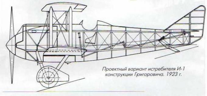
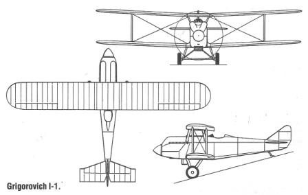
Grigorovich I-1
The Grigorovich I-1 (Russian: Григорович И-1) was designed by DP Grigorovich as a fighter. Knowing that NN Polikarpov was designing a new fighter, Grigorovich decided at all costs to take on a similar task.
The general design was carried out by Grigorovich with the help of VV Kalinin. Engineer AA Krylov was in charge of the aerodynamic calculations. The concept design was conceived in just three days and submitted to the Department of Aviation almost in parallel with that of NN Polikarpov’s fighter of the same name.
The I-1 fighter was a single-seat biplane built basically of wood covered with fabric. The fuselage with a wooden structure was characterized by its constructive simplicity. The sides were straight, with some curvature at the top and bottom. At the bow and with a large aerodynamic hub covering the propeller was the 400 hp M-5 water-cooled engine (licensed copy of the North American Liberty L-12), completely covered by an aerodynamic aluminum hood. The original cooling system included a circular-type Lamblin radiator located between the main landing gear. Problems with motor heating motivated several modifications of this radiator. The entire rear region of the fuselage was covered in fabric.
The wing, of a single section, had planes of equal span linked by means of parallel interplane uprights made of wood and 12 mm bracing straps. The selected airfoil was the Gettingen 436. The upper plane had shutter-type ailerons.
The tail was monoplane, of conventional configuration. The construction was of wood covered with fabric. The horizontal, cantilever-type planes featured large-area elevators. The rudder was attached to a small triangular keel.
The landing gear was of the conventional type, with a tail skid and fixed landing gear, linked by a bar.
The pilot was located in an open cockpit located behind the wing trailing edge. The control system was rigid.
The armament designed two 7.62 mm machine guns, although there is no evidence that they were ever installed in the prototype.
The construction of the Grigorovich I-1 was developed within the experimental construction plan of the GAZ No.1. The biplane was completed in September 1923 and on October 5, after receiving the approval of the Scientific Committee of the VVS Directorate (UVVS), it was approved to begin flight tests.
It is noteworthy, that despite Grigorovich’s efforts, NN Polikarpov’s IL-400 (Fighter with Liberty 400 hp) or I-1 monoplane would be ready some time before, but unsuccessful attempts to make it fly on August 15 of 1923 definitively reaffirmed Grigorovich’s position.
The first flight of the I-1 took place on October 30, 1923. The Grigorovich I-1 managed to take off without difficulty and during the test flights it was possible to set a maximum speed of 238 – 240 km/h with climb times to 2,000 meters in 5 minutes and to 5,000 meters in 19 minutes. This made it the fastest aircraft on the Moscow airfield. It was defined that the I-1 was the first successful attempt to create a fighter since the end of the war.
The general opinion was that the plane was stable in the air and responded correctly to the controls. As a problem, the presence of overheating in the engine was highlighted, despite the modification on several occasions of the shape of the radiator.
Despite this, the I-1 was considered only as an experimental model and from the very beginning of the tests Grigorovich and his team began to design the improvements, in parallel with the modifications demanded by the flight tests. All these changes and improvements delayed the delivery of the plane for the development of tests at the NOA (acronym for Nauchno Opytni Aerodrom or Scientific Experimental Aerodrome), so that at the time of its appearance there, the plane had been surpassed by the design improved I-2. This new design seemed to present a better disposition for military use.
I-1
Engine: 400 hp M-5
Wingspan: 10.80m (9.0m)
Wing area: 26.80 m²
Length: 7.32m
Empty weight: 1188 kg
Speed at sea level: 238 – 240 km/h
Landing speed: 95 km/h
Range: 600 km
Endurance: 2 h30 min
Practical ceiling: 6000m
Time to 2000m: 5min
Time to 3000m: 8min
Time to 5000m: 19min
Accommodation: 1
Armament: Two 7.62mm machine guns
Grigorovich IP-3 / DG-53
The IP-3 fighter, which received the manufacturing name DG-53 (Russian: Григорович ИП-3 (ДГ-53)), basically differed from the DG-52 (IP-1) due to its smaller dimensions, its reduced surfaces and its lower flight weight. It seems that with the IP-3 Grigorovich tried to obtain a fighter for close combat armed with machine guns, but for some reason he drifted towards a utility model equipped with Kurchevski ‘s dynamoreactive cannons. In this case, the cannons were simply smaller in terms of caliber, weight and dimensions.
Grigorovich IP-3 / DG-53 Article
The IP-3 fighter was designed to use the 37 mm APK-11 recoilless automatic cannon, proposed by Kurchevski in 1932. These cannons stood out for their magazine feeding, which allowed the number of projectiles per gun to be increased to 25. Up to 12 projectiles were placed in two magazines and the last one was placed directly in the gun when preparing it. The weight of the APK-11 with the magazines reached 39.1 kg. The explosive projectile weighed between 475 and 500 grams and was ejected from the barrel at a speed of 438-475 m/s. The reloading of the barrel after each shot was done automatically using compressed air located in a 5-liter tank.
In addition to its smaller dimensions, the IP-3 was easily differentiated by having individual exhaust pipes that came out of holes in the hood and the introduction of cantilever wing planes. A novelty in this model was the installation of landing flaps. The Shvetsov M-25 radial engine, developed on the North American Wright Cyclone, remained as the power plant.
This fighter was designed to carry two 37mm Kurchevski APK-11 cannons as well as two light machine guns. Unfortunately, at the time of finishing its construction, the APK-11 guns were not yet available. By the end of 1934 it was decided that the APK-11 guns were not ready and for their acceptance it would be necessary to modify them.
On July 2, 1935 the head of the OKB of Factory No.1 Aviajim DP Grigorovich informed the head of the GUAP GN Korolyov about the completion of work on the prototype. In his letter he wrote:
“The IP-3 aircraft with Wright Cyclone is ready for factory tests and has been received by the LIS of Factory No.1 to carry out the tests. I request your approval to start them.”
Factory tests were started in July 1935. Apparently the hope of receiving the APK-11 guns remained latent and the definition of the future of the plane depended on these works.
With the decision to suspend work on the dynamoreactive guns, the interest in the IP-3 disappeared and the development of the model was not continued. In later documents appears the instruction to delete the IP-3 Shvetsov M-25 of Factory No.1 from the construction plan for 1937.
A second prototype known as the IP-4 or DG-53bis and designed to carry two ShVAK guns instead of the Kurchevski ones, remained in the project phase.
Kurchevsky continued to improve his 37mm guns and even managed to get it approved for mass production, but this weapon never found practical application.
IP-3
Engine: Shvetsov M-25, 700 hp
Wingspan: 9.60m
Length: 7.08m
Wing area: 16.36 m²
Normal takeoff weight: 1548 kg
Maximum speed at sea level: 382 km/h
Maximum speed at height: 435 km/h
Cruising speed: 298km/h
Practical range: 830 km
Practical ceiling: 8800 m
Armament: Two 37mm Kurchevski APK-11 cannons, 25 rds & two 7.62mm ShKAS machine guns.
Accommodation: 1
