Grigorovich IP-1 / DG-52

Grigorovich IP-1 with ShVAK cannons and machine guns in the wings.

A proposal arose to use new-type cannons in airplanes, in which the recoil was compensated by the reactive force of the gases expelled during firing, for which they were known as dynamoreactive cannons (DRP). These guns were lighter than normal guns of a similar caliber.

Grigorovich IP-1 / DG-52 Article

The development theory of dynamoreactive guns was developed in the late 1920s by professor and later academician BS Stiechkin. The engineer LV Kurchevski was in charge of materializing these ideas. The guns designed by him were named APK after Avtomaticheskaya Puchka Kurchevskovo or Kurchevski Automated Guns and would be used for the first time in the IZ fighter developed by Grigorovich.

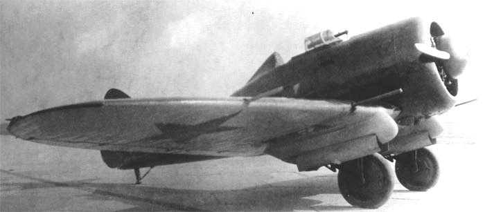
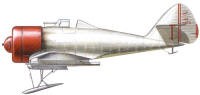
In 1934 D. P. Grigorovich prepared a new fighter armed with APK cannons, which received the factory name DG-52 and was known by the military as IP-1 (acronym for Istrebitiel Puchechni – Gunfighter) (Russian: Григорович ИП-1 (ДГ-52)).

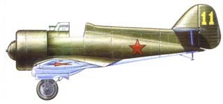
Structurally, the IP-1 was designed as a low-wing cantilever monoplane with all-metal construction. The fuselage terminated in a large-area empennage with the planes set high and braced by struts. The fuselage skin was made with sheets of 1.0 – 1.5 mm. The central wing occupied 55% of the entire span to locate the cannons outside the propeller arc.

The elliptical-shaped wing was designed to achieve the lowest inductive resistance. The wing construction was made up of tubular chrome-molybdenum steel stringers with skeletal ribs made up of rolled profiles with stringers supporting the coating. This wing would later be known as the “Grigorovich Stringless Wing”. The wing covering, with sheets of 0.6 – 0.8 mm, was fixed to the edges of the stringers by means of additional profiles and to the edges of the ribs. The ailerons and landing flaps were designed as shutter type.

The tail was totally metal, but in the production copies the rudders were covered with fabric.

Originally a retractable type landing gear was selected with the ability to carry wheels in the summer and skis for the winter. The undercarriage retracted backwards, leaving the skis inserted in fairings in the wing. This solution, used for the first time in the USSR, reduced aerodynamic resistance to such an extent that the model could maintain performance throughout the year. The landing gear had oleo-pneumatic suspendion and the retraction system had a hydraulic drive. The prototype’s tail skid lacked retraction, but on production examples it would be replaced by a fixed wheel.

The power plant selected was the 640 hp Wright Cyclone SGR-1820 F-3 covered by a long NACA hood. The propeller had metal construction and ground adjustable pitch.

The pilot was accommodated in an open cockpit with a faired headrest in the fuselage.

The armament was similar to that of the IZ fighter, with two APK-4 dynamoreactive recoilless cannons under the wings capable of firing 5 rounds, but instead of the PV-1 machine gun a more effective ShKAS were installed. These machine guns were to serve as aiming rifles for the main recoilless guns.

Grigorovich IP-1 fighter with its APK-4 cannons under the wing midplane.

The state tests of the IP-1 fighter were developed between January and March 1935. The fighter was characterized by high speed and good manoeuvrability, with a turn time of 14-15 seconds. The climb was poor due to the great weight of the cannons.

The military gave an excellent evaluation of the model, highlighting the high speed, the good manoeuvrability and stability in flight, the simplicity of piloting, and the good visibility from the cabin. The great stability of the dive was also highlighted.

The tests showed that the fighter had reservations and problems appeared. Among them, the weakness of the engine hood, the overheating of the oil, difficulties with the control of the plane at the time of departure or retraction of the landing gear, the inconvenience of using the machine gun and the lack of rigidity in the fixing of the APK cannons, among others.

Grigorovich IP-1 prototype color scheme

After the tests carried out between August and September 1935, other defects appeared, such as weakness in the fuselage coating and low effectiveness of the ailerons. It is noteworthy that none of these problems was serious and all could be solved with a certain amount of work, so they did not overshadow the potential of the model. The design collective kept improving the IP-1 until 1936.

The head of the VVS Ya. I. Alksnis demanded that the RKKA VVS Directorate submit its requests to increase the request for IP-1 fighters at the cost of reducing the requests for other fighters.

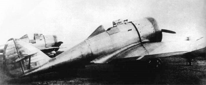
The IP-1 went into production at Kharkiv Aviation Factory No. 135, where a metal aircraft was being built for the first time. In parallel, modifications and improvements began, which were introduced directly into the production process. Early examples were armed with two APK-4s and two ShKAS machine guns.

first production versions with a tapered fuselage

At that time the VVS’s perception of dynamoreactive guns had changed. The results of Kurchevski ‘s APK guns were not what was expected and, on the other hand, conventional guns had already appeared, of smaller caliber, but with greater speed. The Directorate of Special Works (USR), led by LV Kurchevski, was dissolved in February 1936 and this builder would soon be a victim of the repressive wave of those years.

Already in the summer of 1935 Grigorovich had received a request to develop a modification of the IP-1 with 20-mm cannon and machine guns. In January 1937 the first example with this configuration, with factory number 034, was ready and successfully passed the factory tests. Production examples were fitted with two 20mm ShVAK cannons installed in the midplane and the machine gun armament was increased to six 7.62mm ShKAS machine guns (two under each wing console and one in the midplane). The Shvetsov M-25, a license-produced version of the Wright Cyclone F-3, was selected as the powerplant.

Between 1936 and 1937, up to the time production closed at Factory No.135, some 90 IP-1s were built.

These changes brought about a backward movement of the centre of gravity. During the spin tests, carried out at the NII VVS by PM Stefanovski, it was found that the model had problems.

Already at the stage of state tests in 1935, on one of the flights, the plane entered a flat spin from which it was difficult to get out, losing about 800 meters in height in the attempt. At that time it was considered a casual situation, but now, with the changes, the defect was showing up again.

Flight tests were planned to study the phenomenon. During the flight the test pilot AI Nikashin tried all possible manoeuvres, but it was impossible for him to get the IP-1 out of the flat spin and at the last moment he abandoned it by parachuting.

It was decided to begin a research process to improve the aircraft’s behavior in a spin. TsAGI participated in this process. The specialists of this institution came to propose a special parachute located in the tail section to facilitate the exit of the spin, but this solution was finally discarded. Professor AN Zhuravchenko proposed to install a long fin from the headrest to the vertical keel, which should improve directional stability. With these changes the plane was able to get out of any type of spin without difficulty.

IP-1 with new keel installed

A large part of the 90 examples produced ended up being delivered to the 43rd Aviation Brigade. RKKA VVSs used the IP-1 until 1939, when it began to be replaced by the Polikarpov I-16. From there the traces of the IP-1 disappear. The final destination of the withdrawn examples is unknown.

In November 1939 at the NII VVS the flight tests of the IP-1Sh model with a Shvetsov M-25 engine and modified by the institute’s specialists as an armoured attack aircraft were carried out. The modifications were made on a serial IP-1 model produced by the Kharkiv Factory No.135 in 1935.

The model featured armament similar to that of later versions of the fighter, consisting of two 20mm ShVAK cannons located in the midplane and six 7.62mm ShKAS machine guns. The “P” type armor consisted of 6 – 6.5 mm cement plates capable of withstanding impacts from 7.62 mm bullets from distances of 125 m and at angles of up to 35 degrees. This armour covered the vital points of the construction. The fuel tanks were protected by two armour plates weighing 72.8 kg.

The pilot was defended from shots from behind by an 18.5 kg armour plate and on the sides by two 12.6 kg vertical side plates. Frontal impacts were to be covered by the engine. In total all the armour added a weight of 125 kg.

The takeoff weight of this version reached 1,940 kg, so the maximum speed decreased to only 320 km/h at sea level and 343 km/h at 2,000 meters.

In the report of the conclusions of the tests, it was reflected that due to the poor flight performance, the construction difficulties and the appearance of associated difficulties (vibrations in flight and new problems with spin entry), the model lacked prospects for growth.

In order to study the effectiveness of this armour, it was decided to transfer the model to the NII-48 to study the resistance to the impact of different types of weapons.

The tactical specialists of the VVS planned to use the IP-1Sh fighters in chains or brigades, attacking the enemy in dive encounter contacts from distances of 1000 – 1500 from the target.

It was considered that the fighter would be basically intended for attacking ground targets located in a radius of action of 200-350 km or as part of Vaxmistrov ‘s Zvenó combined structures, in order to increase the range of actions.

The IP-1 was Grigorovich ‘s last aircraft to be mass-produced. In 1927 he became seriously ill and the following year died.

IP-1
Powerplant: 1 × 710 hp Shvietsov М-25
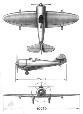
Wingspan: 10.97m
Wing area: 19.98 m²
Length: 7.23m
Empty weight: 1200kg
Normal takeoff weight: 1880 kg
Maximum speed at sea level: 343 km/h
Maximum speed at 3000 m: 410 km/h
Cruising speed: 298km/h
Practical range: 1000 km
Maximum ascent speed: 574 m/min
Practical ceiling: 7700 m
Climb to 1000 m: 1 min 19 s
Armament: Two dynamoreactive 76.2 mm Kurchevski APK-4 cannon – 10-14 shells / one 7.62 mm ShKAS machine gun.
Accommodation: 1

IP-1 fighter in its original version with APK-4 cannon

Grigorovich MR-5

The Grigorovich MR-5 (Russian: Григорович МР-5) flying boat was a development of the earlier DP Grigorovich MR-2 model with a new metal hull. Both the armament and the distribution were similar to the previous model but the power plant was modified to install a 500/680 hp BMW-VI engine.

The project was ready by 1927 and construction began the following year. The new seaplane was developed keeping the same scheme of the previous models. It was a flying boat with a liquid-cooled engine and propeller propeller. The descriptive memory that accompanied the model during the tests defined the MR-5 as “totally made of aluminum except for the wings and side floats” .

The hull was made up of seven watertight departments. In the bow section, a waterproof bottom was installed in an auxiliary way. Round hatches with hermetic hatches were installed to allow passage inside the hull, and a similar hatch was installed in the upper part of the fuselage to allow access to the entrance of the fuel tanks.
The fuel system consisted of two main tanks with a total capacity of 608 liters. There was a third tank of 64 liters. The oil tank was located below the engine cooling radiator, which gave the powertrain an almost triangular cross-section. The BMW-VI engine was fitted with a two-blade wooden propeller 3.18 meters in diameter.

The armament of the flying boat was located in two turrets located in the bow section and in the back (TUR-5 and TUR-6 respectively). Under the wings, on each side, a pair of DER-6 mounts was located, capable of fixing aircraft bombs in two combinations: 4 x 82 kg and 8 x 48 kg.

The MR-5 was completed at Factory No.22 in Fili by the summer of 1929. First flying in July 1929, the tests were carried out between July and August of that year in Taganrog by test pilot ST Rybalchuk. This pilot moved the model to Sebastopol in September, in order to carry out the acceptance tests there.

The tests showed that the flying boat had excellent behaviour in the air. Gone were the stability problems that characterized the earlier MR-2 and MRL-1 models.

The behaviour on the water did not have the same results. It was determined that during takeoff and landing operations, the flying boat raised large curtains of water to the sides due to poor design of the bow. The takeoff and landing runs were also extremely long. The tests of behaviour in the sea with waves were not carried out. The pilots also determined that the aircraft had poor manoeuvrability at a combat altitude of 3,000 meters.

The MR-5 flew at the time of the transfer of the OMOS from Leningrad to Moscow, that is why the plane concentrated all the problems of the moment in its history. Later in OPO-3 it would be confirmed that the work on the creation of the MR-5 was not carried out following the approved scheme: the conceptual project was never approved, the established tests for wind tunnels were not carried out, and in spite of all this the construction was approved in the OMOS and the construction began.

At the time of Grigorovich ‘s arrest, the MR-5 was in the process of being assembled. Builder DP Samsonov was given the task to continue the assembly and carry out the necessary modifications.

The commission to define the fate of the MR-5 was convened for December 1, 1929. The representative of the Technical Scientific Council of the Directorate of the VVS R. L. Bartini participated in this commission. The commission concluded that the flying boat had design problems in the bow section. It was decided not to recommend the MR-5 for entry into service with the RKKA VVS and it was decided that the model would be accepted only when the design of the bow rails was modified and it was submitted again to state tests.

To carry out the proposed modifications, the model was delivered to the OPO-4 directed by Frenchman Paul Aimé Richard, but by that time the benefits obtained had ceased to interest the VVS and despite the fact that two new hulls were built, the aircraft was not finished.

A short time later and in view of the growing need for reconnaissance naval models, the development was handed over to the TsKB at the Menzhinski Factory. There the subject remained without progress until 1931, when the task was assigned to the head of the naval department Chetverikov, who developed the model MR-5bis or TsKB-10.

modified model TsKB-10 or MR-5bis

Variation: Chetverikov MR-5bis

Several well-known Soviet aviation historians in their works refer to this Grigorovich model as the MR-3. This assertion has been later spread by numerous articles, publications and internet sites, which have used these authors as a reference. On the other hand, evidence has been introduced about the MR-5, also by Grigorovich and with such a similar story, that it suggests that it was the same plane. To increase the confusion, researchers, who realized the problem, present the model as MR-3 (MR-5), without clarifying the relationship between the two.

Stranger still it seems that the builder Grigorovich named his reconnaissance model for open sea ROM-1 MR-3 and its derivative ROM-2 MR-3bis. Taking into account that both models (ROM-1 and MR-3) coincide in time, it is very unlikely that the manufacturer used the same name in very different models with the sole purpose of creating confusion in future history.

The renowned aviation researcher and writer Mijail Maslov in the series of articles “Airplanes of Dmitri Grigorovich”, published in the specialized magazine Aviation and Cosmonautics between 2012 and 2013, expresses that from his study of the primary documents of the time in none appear references to this model as MR-3 and yes as MR-5.

In this way we will use the names MR-3 and MR-3bis to refer to the ROM-1 and ROM-2 reconnaissance flying boats and the MR-5 and MR-5bis designations to refer to the single-engine reconnaissance flying boat created as a development with the metal hull of the MR-2 and the improved version made by Chetverikov in 1931.

Grigorovich MR-5

MR-5
Powerplant: 1 x 500/680 hp BMW-VI
Wingspan of upper plane: 15.6 m
Wingspan of the lower plane: 13.65 m
Length: 11.47m
Wing area: 53.0 m²
Empty weight: 2227 kg
Takeoff Weight: 3282 kg
Fuel weight: 440kg
Oil weight: 30kg
Total load capacity: 1055kg
Wing loading: 58.2 kg/m²
Power load: 6.2kg/hp
Maximum speed at sea level: 194 km/h
Cruising speed: 165km/h
Landing speed: 85km/h
Time to 1000m: 7.0min
Time to 2000m: 15min
Time to 3000m: 37min
Practical ceiling: 4000 m
Endurance: 4 hours
Range: 750km
Turning time: 29 sec
Accommodation: 2
Armament: Two 7.62mm machine gun
Bomb load: 4 x 82 kg or 8 x 48 kg

Grigorovich ROM-2 / MDR-1 / MR-3bis

During flight tests in Sevastopol in 1929

In September 1927, when the assembly of the first prototype of the open sea explorer ROM-1 was finished, it was decided to give the green light to the construction of a second prototype, which received the designation ROM-2 or MR-3bis (Russian: Григорович РОМ-2 (МР-3БИС)).

Already in mid-1927 the Aviatrust leadership was convinced that the work of the OMOS naval department in Leningrad was not bearing the expected results, so all experimental work had to be concentrated in the capital.

In September 1927 the decision was made to dissolve the OMOS TsKB and transfer all its specialists to Moscow, placing them in the facilities of Factory No.22 in Fili. About 200 workers were transferred from Leningrad to Moscow, including 44 builders. The organization in the new location was renamed OPO-3 (acronym for O pytni P roizvodsvenni O tdiel – 3 or Experimental Productive Department – 3). In practice, this transfer process lasted until the first quarter of 1928. In the documents of this period related to the start of the activity of the EPO-3 it can be seen that the financial situation was destabilized and losses of state assets were recorded.

On 27 June 1928 the president of the Aviotrust , MG Uryvayev, called a meeting in the building of the EPO-3 in which the director of the factory No.2 FS Malakhov participated PD Samsonov as a representative of the OPO-3 (Grigorovich was in Sevastopol in the process of continuing the ROM-1 tests), VI Nikitin as replacement for the head of the OPO. The meeting basically touched on the problems of the new situation. It was reported that in Moscow the acceptance of the Leningradense group had not taken place and that the interrelation with the factory was progressing with difficulty. The facilities provided for the work were small and insufficient for the staff, their repair extended over time. The phone connection had only been running for a month and a half.

The supply of materials was defined as lousy, the workers assigned by the factory were all of low qualification, the salary for the members of the OPO-3 was lower than that of the rest of the factory workers (this was explainable because despite that the OPO-3 was considered a section of Factory No.22 was not subordinate to its technical line). It was also said that for housing issues of the 13 employees received, half had already left the department (later, the abandonment of the OPO-3 by specialists and collaborators would increase in such a way that by the end of 1928 only 50% remained of transferred personnel).

Under these conditions, ROM-2 was built.

Originally the main difference between the ROM-1 and ROM-2 was the installation in the latter of two German BMW-VI 500/680 hp engines located separately on the wing, but during the construction process important modifications were made. In the work records of the OPO-3 it is stated that in Factory No.22 a new hull and elliptical wings were built for this hydrofoil.

The upper wing kept its wooden construction, but its plan view showed an almost elliptical shape with ailerons of increased area and a surface area greater than 5 m². The leading edge had less curvature than the trailing edge. On this occasion, the extrados of the centroplane featured a corrugated aluminum coating. The wing consoles featured a double stringer structure with plywood covering from the leading edge to the position of the second stringer. From then on, the covering was made of fabric. The ailerons and the tail section kept the fabric covering.

The lower metallic wing was little different from the original ROM-1, but the underwing floats lost their reef and were fixed with small piles to the wingtips.

The hull was lowered by 1.5 meter. The contours of the ROM-2 were quite different and were characterized by increased transverse sagging in the keel area with the sides concave on the bottom, which ensured a smoother landing, especially in swell. In the lower zone, near the recess, the coating reached 1.5 mm. In the rest of the helmet 1 – 1.2 mm.

The fuel system was modified. Three fuel tanks with a total capacity of 810 liters were installed in the center of the hull. A fourth tank with a capacity of 310 liters was installed in the center plane. During the tests, the engines used 3.25 and 3.5 metre propellers interchangeably.

The ROM-2 crew was maintained with 4 people and its defensive armament consisted of two points of fire operating paired Lewis or DA machine guns. A TUR-6 turret was mounted in the fore area and a TUR-5 in the rear position. Small bombs could be placed on the gunwales as on the Dornier Wal. Larger calibre pumps could be installed under the lower wing. The total capacity of ropes reached 600 kg. As special equipment highlights the installation of a Kodak camera in the rear cabin and a tank with drinking water for long flights.

An anchor was located in the bow, which during the flight was fixed to the upper front deck.

Another distinctive feature of the ROM-2 was the ability to be dismembered in such a way that the hydrofoil could be moved overland using four rail platforms.

ROM-2 in Taganrog

The ROM-2 was to be projected to fly for 5 hours covering a radius of 500 km. Its construction began in Leningrad at the then-renamed Factory No.23 (Formerly GAZ No.3 “Krasni Liotchik”), but was soon moved to Moscow, to the collective’s new location at Factory No.22 in Fili.

The ROM-2 left the OPO-3 workshops at the beginning of July 1929, but only a month and a half later it would be fully ready. At the end of September the prototype was shipped by rail to Sevastopol, where it was assembled and prepared for flights. There it was found that the hydrofoil showed an increase of 690 kg in relation to the projected data.

The date of the first flight of ROM-2 is not exactly known, but it must have occurred around October 1929. As a test pilot, S. Rybalchuk, who had previously flown the unsuccessful ROM-1, was selected.

There is evidence that the short testing period was characterized by minor problems and breakages. On November 6, during the launching process, the lower right wing and the stabilization float broke. On the 29th of that month another accident occurred in Sevastopol, near the Konstantinov battery. That day at 1:45 am Rybalchuk took off and landed with quite rough seas. During the third landing the plane entered facing a wave and as a result several construction elements were damaged.

ROM-2 during the tests in Sevastopol.

The report that was produced highlighted the successful hull design, the spaciousness of the cabin and the good performance in takeoff over the sea. The stabilization float scheme was considered unsuccessful and the lack of rigidity in certain elements of the construction was highlighted. The radius of action of 445 km, maximum speed and manoeuvrability in the air were also highlighted as negative.

In Rybalchuk’s report can be found:
“The performance of the ROM-2 can be considered somewhat superior in relation to the ROM-1, especially in relation to maximum speed and control. The overall performance rating can be considered below average. The machine remains heavy and in this configuration it has no prospects. “

As a conclusion in December 1929 it was considered that the ROM-2 2BMW6 was not ready to enter service with the VVS. It was decided to return it to the factory to repair the defects and deliver it for retesting before August 15, 1930. It was recommended to lengthen the nose to improve the behaviour on the water, review the design of the floats, locate the engines towards the depth of the wing and advance the location of the pilots.

Once at the factory, they worked on repairing the prototype. The hull was shortened by 0.20 meters, the engines were raised on the wing, being located on some N-type structures. Baptized ROM-2bis, the new variant, according to the opinion of military specialists, had nothing to offer either.

Despite the fact that by the end of 1929 in the OPO-3 all the detailed plans for the series production of the ROM-2 had been completed and that Factory No.22 had prepared to take on a small series of 22 copies, for reasons not very clear this production would not be carried out. Work on ROM-2 was abandoned and the project for an improved model, known as ROM-3, was never completed.

Grigorovich ROM-2
Engines: 2 x 500/680 hp BMW VI
Wingspan: 26.80 m
Wing area: 108.20 m²
Length: 17.40 m
Empty weight: 4150 kg
Normal takeoff weight: 6587 kg
Oil weight: 90 kg
Total load capacity: 2437 kg
Wing loading: 61.0 kg / m²
Power load: 4.9 kg / hp
Maximum speed at sea level: 180 km / h
Maximum speed at 3000 m: 163 km / h
Landing speed: 95 km / h
ROC: 143 m / min
Turn time: 50s
Range: 900 km
Endurance: 5 h
Service ceiling: 4500 m
Time to 1000 m: 7.0 min
Time 2000 m: 14 min
Time 3000 m: 22 min
Practical range: 900 km
Landing run: 170 m
Take-off run: 250 m
Accommodation: 4
Armament: 3 x Lewis or DA machine guns in turrets TUR-6 (forward) and TUR-5 (in the rear fuselage).
Bombload: 600 kg

Grigorovich ROM-1 / MR-3

On June 17, 1925, the Scientific Committee of the Directorate of the VVS (UVVS) approved the technical task for the development of an open sea exploration airplane (ROM according to the initials of Razviedchik Otkrytovo Morya) with two Lorraine-Dietrich engines of 450 hp. Almost in parallel OMOS was tasked with creating a hydrofoil to cover this request.

Development of the Grigorovich ROM-1 (in Russian: Григорович РОМ-1) commenced in the summer of 1925. The aircraft was ordered during Summer 1925, the task was considered of high priority. According to the TZ, the hull had to be all metal (aluminum alloy), the wing – wooden. V.B.Shavrov was responsible for hull design, P.D.Samsonov – for wing and powerplant. The hull layout was chosen as simple as possible to avoid complicated procedures.

The ROM owes its name to the initials of Razviedchik Otkrytovo Morya or Open Sea Explorer, but the company internally called it MR-3 (Morskoi Razviedchik – 3) and apparently the Navy also called them MDR-1 (Mosrkoi Dalni Razviedchik – 1), so in literature it is sometimes named in these ways. Shavrov also used the name MR-3 to refer to Grigorovich’s MR-5 model, which has contributed to some confusion, although today there is consensus that this was an error by the author.

The ROM-1 (ROM = Razviedchik Otkrytovo Morya [Open Sea Reconnaissance]) was a long range maritime reconnaissance sesquiplane flying boat with two engines installed in a tandem nacelle, supported on struts over the hull. The hull was made from aluminum and the wings were made of wood, attached to the sides of the engine nacelle. The water-tight lower wings, attached to the sides of the hull, were installed slightly above the waterline and carried two floats on their tips. The ‘wing box’ included 20 struts. Thickness of the walls was from 1.0mm above the waterline and 1.5…2.0mm below. The tail surfaces had aluminum alloy frames with fabric covering.

The upper wing, built in wood, had a span of 27 meters with a total area of 86.6 m². The two stringers of the upper wing had a trunk-like structure. Initially each of them had a single thickness of 100 mm throughout the span, but later pairs of 60 mm thick were installed. The wing nerves were skeletal in type. In the upper part of the wing from the leading edge to the second spar the covering was plywood covered with fabric and from there only fabric. The upper wing had a Gettingen-426 profile, but a thicker Gettingen-420 profile was used in the area where the supports were attached, so when looking at the model from the front, the variation in wing thickness could be clearly appreciated, which widened towards the center of each half plane.

The lower plane was made entirely of aluminum and, like the helmet, was covered in waterproof coated fabric. The stabilization floats were located in the external section of the intrados, which had a semicircular section in the upper part and a configuration of a reent in its lower part. Fixing to the wing was done by eight small steel supports.

Originally all the joints were caulked with layers of fabric covered with anticorrosive or tar, but here a mistake was made: the tightness was achieved but the thickness of the layers at the seams tried against the finish. Soon all this work would be scrapped and the joints would be covered with waterproof tape, giving the finish more aesthetics.

The bracing between both planes was achieved by means of 20 diagonal supports and two stiffness frames, which was directly reflected in the increased weight of the structure. The inner interalar supports were made of aerodynamically shaped aluminum tubes but the outer ones were made of rectangular profiles.

Samsonov proposed the installation of two 450 hp Lorraine-Dietrich engines, located in tandem and opposite on the centroplane, so that they moved a traction propeller and an impeller. The need to move the engines forward to improve the c of g resulted in the need to locate two steel supports located forward on the hull, just in front of the cockpit.

The ROM-1 crew consisted of four people. In the bow area a gunner was installed operating a pair of Lewis machine guns in a TUR-4 turret with a Herts collimator. Two crew members: pilot and mechanic, sat side by side in an open cockpit, located in front of the wing leading edge and protected by a small windshield. In the rear section of the fuselage, just behind the propeller, there was another defensive position covered by the fourth crew member, operating a pair of machine guns in a TUR-5 turret, which covered the rear hemisphere. A number of bombs could be attached to both sides on Sbr-8 brackets and bomb aiming device in the nose cockpit.

The centering of the hydrofoil was the cause of the biggest headaches. To achieve good stability it was necessary to position the engines well forward, increasing the length of the driving nacelles and installing two new interplane supports not conceived in the original project, which added a little more weight to the construction. Despite this, the rear centering was still outside the permitted limits. This had to be corrected by the crew before take-off by distributing cargo and fuel.

In the process of developing the ROM there were important variations in the request of the military. Despite having approved the project as a reconnaissance aircraft, on May 31, 1927, the Aviatrust requested the possibility of considering the installation of a Type 1915 450 kg torpedo. Grigorovich objected that this installation would bring important changes in the project and the need to use more powerful engines, but finally he would develop a conceptual project with this configuration that is known as MT-1 (MM-3).

Built at GAZ No.3 “Krasni Liotchik” of Leningrad, in order to build the metal hull, it was necessary to prepare the production in Leningrad of the aluminum sheets, pipes and rivets, since the AGOS profiles, which were already being produced, could not be used. In western countries these elements were already manufactured in large quantities but Soviet finances in the 1920s could not afford such expenditures.

On the other hand, a new need also arose: to develop the structural elements of the hydrofoil hull, designed from angles with profiles of 1.5 – 2 mm thick and 800 mm wide. The cross section of the hull had the shape of a pentagon all along with the tip pointing downwards, since a certain angle (12º) was conceived in the keel area. The majority use of straight lines with simplified contours was maintained. The recess had a height of 150 mm and an inclination of up to 45º.

On September 15, 1927, the management of the “Krasni Liotchik” factory declared that the ROM was practically ready, leaving only to stretch the fabric covers and complete the equipment. Already abroad, the hydrofoil was assembled and painted and on September 27 the Aviatrust technical committee gave the green light to the delivery for the flight tests. In parallel the OMOS TsKB was tasked with starting the construction of a second prototype. From this moment on, the first prototype was called ROM-1 (MR-3) and the new prototype ROM-2 (MR-3bis).

In the spring of 1927 static tests were carried out, which showed that in general the construction of the hydrofoil could be characterized as resistant. The wing, however, showed a deflection of 0.3 meters under normal overloads and up to 1.5 meters before breaking, prompting the replacement of the 100mm spars with a 60mm pair. The center plane section was also reinforced. Unfortunately these measures increased the weight of the aircraft by about 600 kg. The ROM-1 suffered from same problem as some other aircraft of D.P.Grigorovich – too rear CG location. To fix the problem engines, fuel tanks and payload were moved forward.

The prototype ROM-1 built at GAZ-3 first flew in the autumn of 1927. The first flights were made in Leningrad, in the immediate vicinity of the Grebni test station.

At conclusion of the flight test pilot L. Giks wrote:
“The take-off from the water took place at a speed of 97 km / h with an ascent speed of 3 meters per second. The flight took place at an altitude of 400 meters. Gliding at a speed of 110 km / h with engines off was stable. The speed recorded on landing was 85 km / h.
During the circle flight the handling was normal. The aircraft responds well to the ailerons, but the rudder surface is insufficient. He responded better in the height shot. Backward centering is felt and the plane finds it difficult to dive. In general, the aircraft is heavy at the controls, which can be explained by the low speed with a very large take-off weight. “

The tests of the model carried out in Leningrad until November 1927 were characterized by the absence of a defined system or program. Grigorovich felt quite uneasy during those days, he took the project with a certain coldness and did not even show up to the tests, something unusual for him. The OMOS had received the order to leave Leningrad and move to Moscow to locate in a factory in Fili where the OPO-3 of the TsKB would be created.

On November 21, 1927, with the beginning of the winter frosts, Dmitri Pavlovich ordered the aircraft to be dismantled, moved to the commander’s airfield, packed the parts in boxes, and shipped to Sevastopol.

At the end of November 1927 the ROM-1 was sent to Sevastopol, where the flight tests were continued.
On February 24, pilot Giks reported:
“Take-off takes place at speeds of 90 – 95 km / h. During the flight you feel pressure on the legs, but not great. I reached the height of 3200 m. At speeds between 80 – 90 km / h the landing is excellent. With a load of 1500 km the maximum speed is 158 – 162 km / h. Ailerons are not very effective. “

In June 1928 it was decided to send the ROM-1 to Taganrog with the aim of making a number of improvements there. Grigorovich arrived in Sevastopol, who was to continue with Giks towards Taganrog, but none of this happened. A couple of months later, upon arriving in Moscow, Grigorovich was arrested.

The work on ROM-1 was continued under the direction of P. D. Samsonov, as representative of the OPO-3. As of August 20, 1928, a series of modifications were made that included the installation of new 2.96 m diameter propellers obtained from a Farman, internal changes in the cabin, addition of 900 × 200 mm wheels (from a Vickers Vernon), which could be installed to facilitate the entry and exit of water, among others.

In Sevastopol the flights were carried out by the pilot S. T. Rybalchuk. After the changes, a certain number of flights were made in which the flight characteristics were not fixed. In the final report, written in the fall of 1928, the pilot wrote:
“The excess weight of the construction does not allow to load the total capacity of fuel for prolonged flights nor the completion of the armament. The weak Lorraine engines of only 450 hp are not sufficient for normal piloting of the airplane at maximum payload. I consider that the ROM-1 in the current state cannot be used in the proposed mission. “

The situation became doubtful, but the opinion had been created that the ROM-1 could not be used as a military model, so it was simply left in the open awaiting decisions from the commanders.

Shortly before the 1929 flying season they remembered ROM-1 again. The prototype was admitted to Factory No.31 in Taganrog for review. Mechanical engineer K. N. Ganulich wrote in the report:
“As a result of the plane being in the open all autumn, the wooden wings have been damaged in such a way that they need to be repaired. The entire interior surface has been filled with water, the coating has become moldy, and the plywood layers have separated at the leading edge. The worst condition is the leading edge and ailerons. The helmet is in good condition. The coating lacquer is fine. “

The ROM-1 repairs were carried out between April and mid-May 1929. The hydrofoil was again flown and sent to Sevastopol. On June 17, 1929, the assistant to the head of the VVS RKKA Ya. I. Alksnis gave the order to conduct state testing of the ROM-1, ROM-2 and MR-5 models.

The tests began in Sevastopol on July 2, 1929. The first attempts, carried out in Golandia Bay, showed that with a center of 30.4% the hydrofoil did not lift the bow. They were forced to return to a base in Najimov Bay, where a person moved into the rear cabin and a 40 kg dead weight was added there. With this, it was possible to move the centering to 35% and it was possible to take off without difficulties, but warming of the engines was appreciated.

At night, when the temperature dropped, Rybalchuk managed to make a flight in which a height of 3470 meters was set. The next day new radiators taken from a Dornier Wal were installed and several flights were made until August 2. A total of 84 flights were executed in ROM-1.

In preparing the report Naval Aviation NII engineer Korovin wrote:
“Poor visibility from the cockpit, hard controls, sensitive pedal pressure on the right leg, complex starting system. Shallow cabin, high deck. Pilots cannot exchange positions in flight. “

It was also found that, with a load of 1305 kg in calm sea, take-off was impossible. The tests had to be carried out with loads of 1135 kg.

On September 19, 1929, a commission, made up of specialists from the NII under the direction of the head of the Black Sea VVS Lavrov, defined that the ROM-1 could only be used in pilot training tasks or as a transition model to operations.

The withdrawal of the ROM-1, as late as 1928, from flight tests was a terrible blow to Grigorovich’s reputation.
The extremists accused him of being a saboteur and wasting the valuable resources of the Soviet state on experiments. On September 1, 1928, Grigorovich was removed from his position and arrested under the accusation of developing anti-Soviet activities within the famous Prompartia case.

Only after the failure of the ROM-1 did Grigorovich come to understand the importance of accuracy in aerodynamic calculations, the resistance of materials and the details of operation. And despite the fact that the evolution of global hydroaviation passed before his eyes and to some extent with his participation, Grigorovich unfortunately drew few useful conclusions for himself from this process.

Grigorovich ROM-1
Engines: 2 × Lorraine-Dietrich 12E W-12, 340 kW (450 hp) each
Crew: 4
Length: 16.0 m (52 ft 6 in)
Wingspan: 28.0 m (91 ft 10 in)
Wing area: 104.6 m2 (1,126 sq ft)
Empty weight: 4,518 kg (9,960 lb)
Max takeoff weight: 5,830 kg (12,853 lb)
Fuel weight: 775 kg
Oil weight: 185 kg
Total load capacity: 1312 kg
Maximum speed: 165 km/h (103 mph, 89 kn)
Cruise: 132 km/h
Range: 800 km (500 mi, 430 nmi)
Endurance: 5 hours
Service ceiling: 3,470 m (11,380 ft)
Time to 1,000 m (3,281 ft): 10 minutes 6 seconds
Time to 2000 m: 25.3 min
Time to 3000 m: 54 min
Takeoff Speed: 118 km/h
Landing Speed: 85 km/h
Landing Roll: 13 sec
Takeoff Roll: 25 sec
Turn time: 80 sec
Wing loading: 56.0 kg/m2 (11.5 lb/sq ft)
Armament: 4 x 7.62 mm (0.300 in) DA machine guns
Crew: 4

Grigorovich MUR-1

By 1924 the few M-5 and M-20 trainers still in flight condition had aged and needed constant efforts to keep them operational. The possibility of building new models was considered unproductive.

For this reason the 26 of June of 1925 Grigorovich was tasked to develop a flying boat training flight Soviet schools. An easy-to-build, stable in flight and cheap to operate two-seater hydrofoil was required. The new trainer was to replace the M-20 and MU-1 in service.

The Grigorovich MUR-1, (Russian: Григорович МУР-1, MUR – Morskoi Uchebnyi Rhône – seaplane trainer Rhône) was developed by the Grigorovich Design Bureau. In order to speed up the development process and facilitate the introduction into production, Grigorovich decided to use the hull of the M-5 (M-20) hydrofoil. The new design would only comprise the wing box and the tail unit. A 120 hp Le Rhône (M-2) engine was selected as the power plant. The MUR-1 differed from the Grigorovich M-5 in that it used a more powerful engine, single bay wings with thicker section, and stronger tail structure to reduce the twisting effect of this area during turns. Speed was increased, but other characteristics suffered. The new model introduced of ailerons on both planes.

The two crew members were located in an open cockpit, seated side by side and protected by a small windshield.

Built at GAZ Factory No.3 Krasni Liotchik of Leningrad, the prototype was completed in 1926. The tests, developed by the pilot TS Zhukov at the end of that year, showed an increase in speed, which was set at 120 km / h, but other indicators were lower than those of the M-5.

It was found that the center of gravity had been too far back, so that in hydrofoil it lacked stability in the air with a constant tendency to raise the nose. The structural reinforcement of the tail also contributed to this behaviour, which is why it was necessary to place additional weights of about 32 kg in the bow to restore balance.

It was clear that with these “adaptations” the MUR-1 could not reach production. Despite this, the need was such that it was decided to accept prototype in September 1926. In October of that year, TS Zhukov made the first training flight with pilot Rastyagayev on board as a student.

In 1929, when the TsAGI hydrochannel was created, the MUR-1 was used to carry out pressure studies on the hull. For this purpose, it was equipped with membranes with sensors attached to dynamometers with input from TsAGI engineer N.N.Podsevalov, which measured the forces of the water at different points. These experiments would continue with a slightly modified MUR-2 version.

Test flights were conducted 1929-1931 with the intent to test load condition during taxi, takeoff and landing.

Engine: 1 × Le Rhône M-2, 89 kW (120 hp)
Propeller: 2-bladed fixed-pitch wooden
Wingspan: 11.5 m (37 ft 9 in)
Wing area: 33.0 m2 (355 sq ft)
Length: 8.0 m (26 ft 3 in)
Empty weight: 700 kg (1,543 lb)
Gross weight: 1,000 kg (2,205 lb)
Fuel capacity: 124 kg (273 lb)
Total load capacity: 300 kg
Wing loading: 33.3 kg/m2 (6.8 lb/sq ft)
Power load: 8.4kg / hp
Maximum speed: 129 km/h (80 mph, 70 kn) at sea level
Alighting speed: 95 km/h (59 mph; 51 kn)
Range: 360 km (220 mi, 190 nmi)
Endurance: 3 hours
Service ceiling: 3,500 m (11,500 ft)
Take-off distance: 250 m (820 ft) / 22 seconds
Alighting distance: 170 m (560 ft) / 15 seconds
Time to 1,000 m (3,300 ft): 8 minutes
Time to 2,000 m (6,600 ft): 19 minutes
Time to 3,000 m (9,800 ft): 38 minutes
Crew: 2

Grigorovich MR-2 / MRL-2

In November 1925, the leadership of the VVS highlighted the difficult situation of naval aviation, considering it incapable of fulfilling the tasks set due to the lack of modern seaplanes. In the speech of November 10 and in relation to Grigorovich it was written:
“Of the national builders, only the engineer Grigorovich has the experience in the construction of seaplanes, however two of his last hydro-apparatuses have been unsatisfactory, because without laboratory research at the present time it is impossible to obtain good results.”

By November 1925 and on Grigorovich’s own initiative in the GAZ No.3 in Leningrad, work began on a second example of the MRL reconnaissance flying boat. The Aviatrust management protested against the constructor’s decision, which proposed not being able to fulfil the state order and nevertheless assumed a new design of its own, but finally ended up accepting to include it in the industry plan for 1925 / 1926 under the name MRL-2 (Russian: Григорович МРЛ-2 (МР-2)).

Initially the new model was also designed using a Liberty engine but later it was decided to use a Lorraine-Dietrich engine. For this reason the name used later was MR-2 according to the acronym Morskoi Razvietchik or Naval Explorer.

About this flying boat VB Shavrov wrote:
“Externally it was more beautiful than the MRL-1. The same hull coating, but with a larger area using pine and less mahogany, which at the bottom had a single layer. The rails of the forward section were modified and the upper wing received an increase in its span. The wing bracing cables were made with 5 mm steel cables with rounded ends. The main braces had three and the rest had two cables. The overall dimensions were slightly increased in relation to the MRL-1.”

The new model was developed as a flying boat with a liquid-cooled engine and propeller propeller.
The double reed hull was made of wood and had been lightened in relation to the predecessor MRL-1, maintaining a similar structure.

The wing had a sesquiplana configuration with the lower plane slightly smaller in span and with a certain positive dihedral. The planes were secured by uprights in pairs made of steel tubes with tension cables and had a marked offset. Small stabilization floats were located on the outer sections of the lower plane wing gondolas.

The tail was of the monoplane type with the stabilizers installed on a short keel and braced by simple struts. The keel ended in a small rudder.

The 450 hp Lorraine-Dietrich engine was attached to the upper midplane structure. The fuel system consisted of two main tanks located in the hull, with a third 64-liter tank installed in the midplane.

The armament of the seaplane was located in two turrets located in the bow section and in the rear part. Under the wings, on each side, the fixing of a certain number of bombs was foreseen.

On June 18, 1926 the prototype was finished in the GAZ No.3 workshops. In September it was submitted for testing. Among its main characteristics, the cheapening and simplification of construction stood out, which should be reflected positively in the characteristics of the seaplane and in the production process.

The MRL-2 flying boat was analyzed by a commission composed of II Mashkievich and Ye. K. Stoman of the Directorate of the VVS, and DP Grigorovich and VL Korvin for Factory No.3.

This commission noted that the new model differed from the MRL-1 in the shape of its wings, the improvements made to the hull, its engine covered by a well-designed hood, and the backward displacement of the firing point.

The first flight of the MR-2 took place on September 22, 1926 and lasted 15-17 minutes. The forward position was occupied by DP Grigorovich himself, while pilot AS Melnitsky sat next to VL Korvin at the controls. That same day a second flight was made in which, together with Melnitski, the motorcyclist Funtikov and the engineer Vigand flew. The third flight was made by NOA members with pilot VN Filippov at the controls. This pilot highlighted the long run on takeoff and landing, lack of stability in horizontal flight and during glide. Melnitski had pointed out that the control and transverse stability of the MR-2 were superior to those of the MRL-1 and only the longitudinal was somewhat worse.

It was precisely the longitudinal stability that caused the accident of the pilot FS Rastyagayev that occurred on October 19, 1926. Rastyagayev was not a naval pilot and had no flying boat experience, yet he was the person commanded from Moscow to conduct the first stage of the state tests. On October 18, he made a familiarization flight together with factory pilot Zhukov in a MUR flying boat (M-5 training flying boat with a 120 hp Le Rhône engine) and later he made a solo flight. In his opinion there was nothing special about naval aircraft:
“ – No problems. No difference.”

The next day Rastyagayev took off, circled over the bay, and then glided too steeply. Subsequently, the MR-2 dived, inverted and fell onto a sandbank covered only by a meter and a half of water. The pilot was pulled from the wreckage with a number of injuries and that night he died.

The commission investigating the event, chaired by NM Tulupov, originally concluded that the accident occurred due to the pilot’s lack of familiarity with naval models. In the official minutes of the commission presented on November 27, 1926 , it was written:
“The MR-2 is unstable in the longitudinal axis. At small angles of flight it does not reach the work of the rudders. When the pilot Rastyagayev went into glide he performed a ground pilot maneuver pulling the stick sharply towards himself which caused the plane to dive. On a second attempt the rudders did not respond, going into an inverted dive.”

A more detailed study of the catastrophe was later carried out. A scale model was urgently made and tests were carried out in the wind tunnel of the TsAGI . These tests showed that the cause of the accident was the lack of longitudinal stability of the MR-2 when flying with 48% cog and having the stabilizers set at a positive angle.
The commission established that if the aerodynamic tests had been carried out earlier, this accident could have been avoided.

It is noteworthy that the history of the MR-2 is coincident with that of Polikarpov ‘s Il-400 fighter, which was also destroyed during its first flight due to poor center of gravity selection. The cause of these accidents cannot be seen only in the inability of theoretical calculations. To a large extent, the self-sufficiency of its creators, Polikarpov and Grigorovich, who underestimated the scientific possibilities of institutions such as the TsAGI, played a role, considering that his experience was more than enough to achieve successful designs. This was not an isolated case. Many Soviet constructors presented important problems in the way of carrying out their constructions without the support of aeronautical science.

In any case, after the MR-2 accident, the aerodynamic centering of models was defined as one of the main aspects in aeronautical construction and wind tunnel testing was established as an obligation in the approval process of an aeronautical project.

MR-2
Engine: 1 × Lorraine-Dietrich 12E, 340 kW (450 hp)
Wingspan: 15.6 m (51 ft 2 in)
Wing area: 56.7 m2 (610 sq ft)
Length: 13.6 m (44 ft 7 in)
Empty weight: 1,770 kg (3,902 lb)
Gross weight: 2,770 kg (6,107 lb)
Fuel weight: 560kg
Total load capacity: 1000kg
Wing loading: 49.0 kg/m2 (10.0 lb/sq ft)
Power Load: 6.2kg/hp
Maximum speed: 179 km/h (111 mph, 97 kn)
Landing speed: 82km/h
Range: 900km
Endurance: 5 hours
Service ceiling: 4,200 m (13,800 ft)
Time to 1000m: 7min
Time to 2000m: 17min
Time to 3000m: 34min
Armament: 1-2 x machine guns
Crew: 2

Grigorovich E-2 / DG-55

The Grigorovich E-2, or DG-55 (Russian Григорович Э-2, ДГ-55), was a two-seat, twin-engined, low-wing, prototype sport aircraft of Soviet origin.

Inspired by the de Havilland DH.88 Comet racer which had won the MacRobertson Air Race in 1934, the Grigorovich OKB began work on a similar aircraft. Like the DH.88, the Russian “Kometa” was a highly streamlined conventional low-wing monoplane with twin engines forward of retractable main undercarriage in nacelles under each wing. Built of wood, it also featured an enclosed cockpit and landing flaps.

Intended to be a lightweight, high-speed sport aircraft the DG-55, later designated the E-2, was slightly smaller than the DH.88 and with less powerful engines, using the 120 hp (89 kW) Cirrus Hermes.

Only one prototype was constructed, flying in 1935.

Following completion of its flight tests, the E-2 Kometa was handed over to the OSOAVIAKhIM paramilitary sports organisation, who used it for light liaison duties.

Engines: 2 × Cirrus Hermes, 89 kW (120 hp) each
Propellers: 2-bladed fixed pitch propellers
Wingspan: 11 m (36 ft 1 in)
Wing area: 13.8 m2 (149 sq ft)
Length: 7.9 m (25 ft 11 in)
Empty weight: 1,051 kg (2,317 lb)
Max takeoff weight: 1,546 kg (3,408 lb)
Maximum speed: 296 km/h (184 mph; 160 kn)
Cruise speed: 265 km/h (165 mph; 143 kn)
Range: 2,200 km (1,367 mi; 1,188 nmi)
Service ceiling: 5,000 m (16,000 ft)
Crew: 2

Grigorovich M-24 / MR-4 / Shchetinin M-24

M-24 No.1721 “Krasni Putiloviets”

The last representative of the M family of naval flying boats. In practice, it turned out to be a modification of the excellent M-9 with a more powerful power plant and some structural changes. Dmitri Grigorovich was active during the 20’s in the gas plant No.3 “Red Flyers” in St. Petersburg, where he began the development work on the M-24 (Russian: Григорович М-24) Soviet biplane flying boat in April 1922.

Despite the initial failures with the M-23, the modernization of the M-9 model continued its course. Grigorovich, knowing of the tests of the Renault – engined M-9bis model developed in 1921, decided to propose his improved version of the M-9, which comprised a major redesign. The VVF needed a quick result and for this reason he decided to proceed with as few changes as possible, keep the old hull, avoid structural modifications and concentrate his attention only on the powerplant and wingbox. Grigorovich, from the beginning he was opposed to this procedure, as he understood that in this way it would be impossible to achieve good seaworthy conditions, but the Main Directorate of the VVF in its efforts to achieve results was willing to accept certain limitations and finally the builder decided to satisfy his client.

The design was based on its successful M-9. Some of the differences in the M-24 was dual wings ailerons, and the total area of the hull was changed.

On July 19, 1922 at the State Aviation Factory No.3 “Krasni Liotchik in Petrograd, a commission of the aeronautical department of the Main Directorate of Military Industry (GlavBoyenProm) met and studied the capabilities of the factory and analysed the possibility of building eight new flying boats with the M-9 hull and Renault power plant. In August of that year, during the creation of the industry production program for 1922-1923, the construction of 56 M-9bis was approved.

The first pre-production M-9bis (shortly later renamed M-24) before testing in June 1923.

By May 1, 1923, the first base model of the M-9bis series, with number 1717, was ready and by the beginning of June a commission chaired by the representative of the Scientific Committee of the VVF, the engineer Yermolaiev, developed the first tests of evaluation. The flights were made by naval pilot VG Chuxnovski.
Taking into account the differences between the model modernized by Grigorovich and the M-9bis, the commission decided to approve the new name M-24, classify it as a naval reconnaissance flying boat and gave a positive assessment of the aircraft’s seafaring and aeronautical characteristics. It was decided to authorize its serial production.

Several months later the problems would begin. The complex situation of heavy industry and the lack of supplies led to the decision to close the “Krasni Liotchik” factory as of October 1, 1923 and transfer the request for the production of the M-24 to Factory No.10 in Taganrog, decreasing the quantity requested to only 40 copies. In the midst of this complex situation, the Society of Friends of the Air Fleet (ODVF according to the acronym for Obshesctvo Druziei Vozduzhnovo Fleet) decided to support the aeronautical constructors of Petrograd, financing the creation of the “Krasni Baltiets” squadron (This term could be translated from inaccurately as Red Sailor of the Baltic, since the word Baltiets covers any inhabitant of this area, but in this case it is made with a direct allusion to the Marina – na) with the condition that the production was carried out in the GAZ No.3 “Krasni Liotchik”.

The decision to select the flying boat M-24 as a model for the new squadron was based on the positive report of the commission of the Scientific Committee of the VVF (NKVVF). Agreements with the management of GAZ No.3 to build the first 12 copies of the M-24 were signed on September 12, and by October 7 the GlavBoyenProm submitted to the factory a request for another 15 copies against the funds of the 40 approved.

By its construction the M-24 was similar to the M-9. Both were built with national types of wood. The structure was built with pieces of pine and ash. On top it was covered with birch plywood. The hull was divided into 10 watertight departments. All joints were secured by small screws and rivets. The submerged parts of the hull were covered with sheets of copper or brass. A flexible ash bow was attached to the rear of the keel piece, to which the rear ski could be attached in winter.

Although the hull of the M-9 had proven capable of withstanding landings on ice, the greater weight of the M-24 made such manoeuvres inadvisable. For this reason during the winter in the Baltic the M-24s were operated on skis with an installation scheme similar to that successfully used on the M-15 model.

The wings were made of wood, with some reduction in span relative to the M-9, and were attached by two pairs of pine supports. The lower plane had little positive dihedral and the stabilization floats were fixed externally. The tail unit was of typical Grigorovich design.

The M-24s were powered by 220-260 hp Renault water-cooled 12-cylinder engines entirely covered by an aerodynamic duralumin hood. These engines were installed in a wooden structure located in the space between the wing planes and had a cooling radiator at the front.

In the bow area of the boat an oval hatch was opened to locate the machine gun. In its central part and sitting side by side were the pilot and the mechanic.

M-24 No.1727 “Komunna”

The first series, of 12 copies, featured a single 400 liter fuel tank and was characterized by using the 200 hp Renault engine. When the construction began, the factory lacked the plans and technical specifications approved by the NKVVF. Neither did the Navy leadership. For this reason there were notable differences in the characteristics and completion of different copies of the M-24, fundamentally motivated by claims of their pilots or productive considerations. At that time, the poor seaworthiness of the model, announced from the beginning by Grigorovich, was revealed.

M-24

Soon a special commission would be appointed to investigate the problems that the model was presenting. The commission that reviewed the claims towards the first produced specimens concluded that: “the specimens differ in their flight characteristics, but due to their poor navigability they are not suitable for serious work… consider the aircraft requested by the ODVF available only for training flights.” It was decided to withdraw the model M-24 from service.

Grigorovich M-24 factory number 1719 was the second example of the first series named “Volodarski”.

However, the situation for the VVF was extremely complex due to the lack of naval models. Apart from the M-24 the only aircraft of the VVF in 1924 were 30 Savoia S-16 flying boats and 20 Junkers Ju-20 in process of delivery. In this state it was decided to work on attempts to improve the existing M-24. By that time Grigorovich had already returned to Moscow and was beginning his work on GAZ No.1 (formerly Duks), so the modifications were made without his presence.

The second series, starting from issue 1730, featured a 280-litre main tank. The rest of the fuel was located in two tanks of 60 liters located in the wings or in the space between the wing supports.

At least 20 M-24 examples, related to the second series, used Renault engines with power increased to 260 hp by replacing the original pistons with aluminum ones. This series would present other minor differences, which is why in some literature they have been differentiated as M-24bis.

M-9bis

In the period between 1923 and 1924 at the Petrograd “Krasni Liotchik” 43 copies of the M-24 were manufactured (with serial numbers between 1718 and 1760). These would be the last flying boats of the M series.

In relation to the MR-4 the specialists of the Baltic Fleet at the end of July 1925 wrote:
The plane is three-seater, but when placing a man in the bow it tends to pitch and sink the nose. In the air it is more stable with the three crew members, with two you have to keep the lever as it tends to pull upwards. Most of the time you have to work with the right leg. It reacts poorly to spoilers. The plane handles turbulence poorly.
The plane does not have all the instruments. The hull is weak, the plywood is not of good quality. The plane easily loses control. During the replacement of parts, for example surfaces, they seldom coincide. The engine of the MR-4 (Renault 260 hp), but they did not arrive new, but assembled. Clearly, the material used in the distribution system does not have the necessary rigidity, which brings about constant problems. The water pump key also breaks… There have been few cases of engine stoppages in two years – two or three times, but when the damage does occur it is serious: broken connecting rods, deformed pistons…
…The MR-4 has the following problems: a) not very stable, b) the pilot carries out the bombing blindly, he cannot see the target.
…The MR-4 lacks a camera mount and its installation is impossible due to the fact that the camera lens during takeoffs and landings gets splashed with water and then, when being lowered or hoisted, it is necessary to hold the camera in the hands.
…The MR-4 lacks air navigation equipment. The compass is located between the legs of the crew or on the blackboard next to the moving metal parts, which means that it cannot be seen at times.

Launching of an M-24

Of the 43 copies produced, only 28 would be accepted into service by the VVF. Most examples were used in the Baltic theatre, seeing service with the 1st and 2nd OMPAO (Otdielni Morskoi Razviedivatielni Aviaotryad or Independent Naval Air Exploitation Brigades).

The 2nd OMPAO would receive the 12 copies financed by the ODVF and two more. This unit had previously operated the M-9 and M-20 models. Deliveries were made in two groups of 4 aircraft and a final group of 6 between January and June 1924 and the unit would soon be renamed “Krasni Baltiets”. All its devices had their own names on the bow, many times related to the origin of the contribution of the funds. The names and numbers of most of these specimens are known:
M-24 — Factory number 1718 «Petrogradskaya Pravda» (Petrogradian Truth)
M-24 — Factory number 1719 «Volodarski»
M-24 — Factory number 1720 «Krasni Petrogurfin»
M-24 — Factory number 1721 «Krasni Putiloviets»
M-24 — Factory number 1722 «Volkhovstroi»
M-24 — Factory number 1723 «Leningradski Profsoyuci» (Leningrad Trade Unions)
M-24 — Factory number 1724 «Vladímir Ilich»
M-24 — Factory number 1726 «Pskovityanin»
M-24 — Factory number 1727 «Kommuna»
M-24 — Factory number 1728 «Cherepanin»
M-24 — Factory number 1729 «Krasnaya Karelia»
M-24 – Factory number ???? “Krym SSSR”
M-24 – Factory number ???? Bryansky Rabotnik
M-24 – Factory number ???? «Toplivnik»

Two M-24s were sent to serve in the Black Sea, entering service with the 3rd Air Reconnaissance Brigade, based in Sevastopol.

Originally the M-24 was called MR-1, but since the naval version of the Polikarpov R-1 received the same name, the flying boat began to be called MR-4 (acronym Morskoi Razviedchik or Naval Recognizer). By the beginning of 1925, 27 M-24 flying boats remained in service. Some were operated by the Finnish Air Force.

In 1925 the 1st OMPAO based in Peterhof began to receive the Junkers Ju-20 and the few received M-24s began to be withdrawn from service. The copies of the 2nd OMPAO began to be withdrawn, when this unit began to receive the Junkers Ju-20 also during the second half of 1925.

The 3rd Air Reconnaissance Brigade in the Black Sea was equipped with the Savoia S-16, so the M-24s were practically from the beginning destined for training functions.

After 1925, 17 copies of the M-24 were kept as trainers. A number served in the naval brigade of the Leningrad Military School of Pilots-Observers. The last copy in this center was discharged in December 1928.

Several flying specimens were offered free of charge to the “Doboliet” company, which rejected them. An M-24 would be transferred to the OSOVIAJIM around the month of May 1929, without its subsequent destination being known.

Although the M-24 basically served as trainers during their exploitation, they were frequently used in preparation for military tasks. For this reason many M-24s retained armament similar to that of the M-9: a machine gun in the bow.

M-24
Powerplant: One 220 hp Renault V-12
Upper plane wingspan: 14.40 m
Lower plane wingspan: 13.00 m
Wing area: 55.0 m²
Length: 8.8m
Height: 3.40m
Empty weight: 1240kg 1200kg
Maximum takeoff weight: 1700 kg 1650 kg
Wing loading: 30.0 kg/ m²
Power load: 7.5kg/hp
Speed at sea level: 130km/h
Ceiling: 3500m
Endurance: 4 hours
Range: 400km
Armament: 1 x 7.62 mm machine gun
Bombload: 100 kg
Accommodation: 2 – 3

М-24bis
Powerplant: One 260 hp Renault V-12
Upper plane wingspan: 14.40 m
Lower plane wingspan: 13.00 m
Wing area: 55.0 m²
Length: 8.8m
Height: 3.40m
Empty weight: 1280kg
Maximum takeoff weight: 1740 kg
Payload capacity. 500kg
Wing loading: 31.0 kg/ m²
Power Load: 6.6kg/hp
Speed at sea level: 160km/h
Cruising speed: 121km/h
ROC: 68m/min
Ceiling: 4500m
Endurance: 4 hours
Range: 400km
Armament: 1 x 7.62 mm machine gun
Bombload: 100 kg
Accommodation: 2 – 3

Grigorovich M-24

Grigorovich M-23

In 1922 and after a break of 5 years DP Grigorovich returned to aircraft construction with the development of more powerful versions of the successful Grigorovich/Schetinin M-9. Grigorovich considered that for a more powerful engine it would be necessary to increase the structural rigidity, which would entail a reinforcement of the fuselage and the need to modify the lines of the hull, but despite this he decided to continue the development of the already recognized model with the main objective to be able to interest new customers and quickly secure a new position in the aeronautical industry.

At that time, Grigorovich had not yet been able to put together a work team and lacked the facilities to develop it, so the design work began in his apartment in Moscow. He would soon invite old collaborators to his side, among them the engineers MM Shishmariov, Ye. I. Mayoranov and V. L. Korvin-Kerber.

The M-23 (Russian: Григорович М-23) was an interim development of the M-9 line with a new power plant. The initial model project was completed by mid-1923 but was soon abandoned in favour of a modified version designated M-23bis.

The M-23bis was built at the GAZ No.3 “Krasni Liotchik” in Petrograd in the middle of the summer of 1923. During the tests the model refused to take off from the water. The analyses showed that it was a design error of the bow and contour lines of the hull, so the flying boat was stored pending the necessary modifications, but at the end of the year it was destroyed during a flood that occurred in the hangars on Krestovsky Island.

M-23bis
Power plant: 1 Fiat, 280 hp
Wingspan: 12.5m
Wing area: 45.8 m²
Empty weight: 1165 kg
Takeoff weight: 1615 kg
Total load capacity: 450 kg
Wing loading: 35.0 kg/m²
Power Load: 5.8kg/hp
Accommodation: 2

Grigorovich M-2 / M-3 / M-4 / Shchetinin M-2

Despite the poor results obtained with the M-1 flying boat, the Russian fleet command was predisposed towards an effective national flying boat model. On June 28, 1914 , the Naval General Staff (MGSh) wrote:
“The General Staff… to get out of the position, considers it very advisable to start the indigenous construction of hydroplanes and establishes the following conclusions:
1 – Because the hydroplane designed and built at the SS Schetinin and K Society is available, allowing the factory to carry out the tests at the Puerto del Emperador Alexander III aviation station, but on the condition that the pilot be from the factory. In case of success of the tests the flying boat will be acquired for the needs of the Baltic Sea aviation.
‘ In the event that the hydroplane shows good results, the Naval General Staff considers requesting several of these boats after the problems presented have been solved.”

On the other hand, with the war approaching, the Navy leadership, the 2nd rank captain BP Dudorov requested the MGSh without delay to buy from the PRTV and the RBVZ (Russian Baltic Wagon Factory) all the hydrofoils, finished or not, that could be ready in a short period of time.

These factors encouraged Schetinin to redirect the fundamental activity of PRTV towards the development of navalized models. DP Grigorovich was working on a development of the M-1 model, so on July 29, 1914 a contract would be signed for the production of four new improved examples.

The changes introduced were so significant that the resulting aircraft earned the right to be defined as a new model, which came to light as the M-2 (Morskoi (Naval) – 2), Russian: Григорович М-2.

The contract established the delivery of the first copy for the 7th, the second for the 12th, the third for the 17th and the last for August 23, 1914. Each flying boat was valued at 8,000 rubles and instructions were given to collect four Gnôme engines between 80 and 100 hp in Moscow.

The acceptance conditions established the reach of a height of 500 meters in 12 minutes with the 100 hp engine and 15 minutes with the 80 hp, carrying a load of 75 kg above the weight of the crew and the necessary fuel for three flight hours.

The M-2 was a propeller-driven biplane flying boat, generally similar to that of the M-1 and originally the same engine, but its overall dimensions were increased. The hull grew in width in order to accommodate both crew members side by side. The bow also changed its shape from flat to tapered with a concave bottom in the front, while a new three-sided tail section featured new, much higher mounts, to which the considerably larger area stabilizer was attached.

The wingspan of the upper wing was considerably greater than that of the lower wing, but unlike the M-1 the diagonal supports at the wingtips were not used. The biplane box maintained its location on supports above the fuselage and had only large-area ailerons on the upper plane. The lower wings were installed 1m above the hull on the engine support frame.

The triangular section rear fuselage was raised from the water, tail was equipped with a skid, often referred to as the “shovel”.

According to Shavrov the M-2 to M-4 were used to test some novelties such as the variable incidence stabilizers in flight (for this purpose they had an elevator in the lower part of the leading edge) and in the M-4 a ski – paddle with rubber buffer hinged under the tail to improve launch.

The types of wood used were generally similar to those used during the construction of the M-1.

The construction of the model in the Schetinin factory introduced a constructive novelty: for the first time in Russia, the hull was formed inverted, with the keel up. The first M-2 was delivered to the naval experimental station located in the Grebni port of Petrograd only on August 18, 1914, because before that date the hangar was not found ready for its conservation.

The tests of the prototype with the 80 hp Gnôme engine plant began in August 1914. Unfortunately, the prototype was destroyed on the 31st of that month causing the death of its pilot PV Evsyukov. It is noteworthy that VB Shavrov defines this engine as an 80 hp Clerget, which makes this statement appear in multiple articles and sites that reference this source.

The construction of the other examples was stopped until the investigations were completed. The causes of the accident were never established, but no problems related to structural weaknesses or linked to the construction of the model were found, so it was agreed to continue production.

On October 8 at the Schetinin factory, 4 Gnôme Monosoupape engines of 100 hp were received (The engine of the damaged unit was delivered to the RBVZ) and on November 28, 1914 the first of the new units with this power plant and modifications in the selection of the airfoil was received at the Third Naval Station in Revel (Tallinn). Only 12 days later a second copy would arrive. The test flights were developed until December 22 by the pilot of the factory Ya. I. Siedov-Sierov and the fleet pilot Lieutenant II Kulniev, resulting in numerous remarks and proposals for improvements.

On December 20 three FBA (Franco-British-Aviation) flying boats of the six contracted to France on September 12, 1914 arrived at the Third Station. Both because of their construction and because of their performance, they were quite superior to the M-2, which is why the representatives of the Navy took a negative position towards the Schetinin – Grigorovich model. By the end of the year none of them had been able to present themselves to the acceptance tests.

During the winter the company’s mechanic and pilot made the changes so that by the spring of 1915 flights could be resumed. At that time, a series of improved components arrived from the factory and were installed in the second prototype. General tests continued until April 1915, resulting in a climb time of 15 minutes to a height of 1,300 meters.

The third flying boat М-2 code Sch-3 in the fleet register, with Lieutenant VA Litvinov, head of the Kilkond naval station in the cabin.

In general, they received a positive assessment, so on April 25, 1915 they entered service with the Baltic Fleet aviation with the registrations Sch-2 and Sch-3. These served in the Third Revel Station, basically in training missions, until they were discharged in the winter of 1915-1916 (in the month of November according to Maslov). After that date the engines were removed and for some time were kept in Revel. Due to the fact that these examples underwent changes in the wing profile and hull lines during the tests, their name was changed to M-3 (according to Maslov the name M-3 only corresponded to the second of these, since the first kept as M-2 (Sch-2)).

In the summer of 1914 in the Black Sea the situation was calm and by the month of September the Naval Aviation only had six military planes. The situation would change radically in October, when Turkey declared war on Russia. The new situation made it necessary to take urgent measures.

M-4 number 29, belonging to the Black Sea fleet

From a request of the Black Sea pilots and after several talks held by the head of the Russian aviation, Grand Prince Alexander Mikhailovich Romanov, the commander of the Baltic Fleet NO von Essen; the head of the MGSh AI Rusini and the head of the Aeronautical Department of the MGSh AA Tuchkov, the remaining two copies of the contract of four were sent to Sevastopol on March 10, 1915. This measure was aimed at strengthening the capacity of the air forces for the operations to be carried out in the Bosphorus area.

Ten days after the arrival, a PRTV brigade would arrive under engineer AN Sidielnikov and also made up of pilot Ya. I. Siedov-Sierov, two mechanics and two assemblers. On March 24 the flying boats were transferred to the assembly site and on the 31st the commission from the port of Sevastopol arrived to carry out the tests.

They had to make a flight of 25 minutes and another of 13 minutes in which they should reach the contracted height in 7.5 minutes. The planes received the numberings “29” and “30” and were to complement a varied group of seaplanes that made up the Black Sea Fleet aviation. These M-2s would later be referenced in documents as M-2/M-4 or simply M-4.

M-4 number 29

On April 8, 1915, military pilots began familiarization flights and after a series of acceptance tests, the two were accepted by the Fleet, eventually being used in military actions. On April 12, 1915, number 29, armed with a Maxim machine gun in an installation designed by Kryltsov, was lowered into the water from the cruiser “Emperor Nikolai I” in the Bosphorus region. Crewed by A. Ye. Zhukov and SN Korsakov the flying boat managed to carry out an attack on a Turkish gunboat of the type “Burak Reis”, dropping a bomb that exploded about 70 meters from the stern. This was considered the first military action of a flying boat in Russia and could have ended as a major catastrophe: a hose rupture forced the crew to make a landing a considerable distance from the base, but they managed to reach it by sailing.

Reports on the use of the Schetinin / Grigorovich flying boats in the Black Sea theater were promising, but the Aviation Committee had some doubts about the structural resistance of the model, especially since “30” began to present problems with the hull cladding slats, which came off even after normal landings. As a result, on May 15, a document was issued to the factory in which it recommended reducing the angle of attack of the stabilization floats, reinforcing their fixation and modifying the hull in order to add a rudder that would improve operation in the water. PRTV received the considerations but there was little that could be done because the production had culminated with the delivery of the four copies.

The flying boat “30” was decommissioned in October 1915. In the case of “29”, no evidence has been found to define its operating time.

The factory numbers of the delivered were 196 and 197 (the numbers of the others are unknown), The Baltic Sea Fleet of M-3s were Sch-2 and SCh-3. The Black Sea Fleet of M-4s were naval register ”29”, factory number 196, and naval register ”30”, factory number 197.

M-2 prototype
Powerplant: 1 x 80 hp Gnôme
Upper plane wingspan: 13.68 m
Wing area: 33.5 m²
Length: 8.0m
Normal takeoff weight: 870 kg
Wing loading: 26 kg/ m²
Power Load: 10.9kg/hp
Speed at sea level: 115km/h
Cruising speed: 76km/h
Ascent time to 1000 m: 7 min
Ceiling: 4000m
Practical range: 320 km
Endurance: 3.5 hours
Accommodation: 2 side by side

1913 M-3
Span: 44’10”
Length: 26’3″
Loaded Weight: 1918 lb

M-4
Powerplant: 1 x 100 hp Gnome Monosoupape
Wingspan: 13.62m
Wing area: 37.90 m²
Length: 8.00m
Normal takeoff weight: 870 kg
Wing loading: 26 kg/m²
Power load: 8.7kg/hp
Top speed: 100km/h
Cruising speed: 76km/h
Practical range: 320 km
Accommodation: 2 side by side

Grigorovich M-2