The H XII was a light side by side two seater with a 100 hp engine. It was intended as a private owners coupe but R.L.M. were interested in it as a trainer. The first of the type was built and flown at Gottingen (where it was found destroyed in June this year) as a glider; work was also in progress at Kirtorf (sp.) where a mock up of the power center section was found, badly damaged by fire. The wing used a Mustang section at the root graded to a symmetrical section with Mustang fairing shape at the tip. Washout was 3 – 3.5 degrees. Elevon controls were of H VII type with a 20% Frise nose. Plain flaps were fitted with a H IX center section spoiler and “trafficator” drag rudders. The undercarriage was unusual in having two wheels forward and one main wheel aft taking 60% of the weight. All three wheels were retractable. Little flying had been done, but it was found that the same troubles were arising as on the H IVb. The laminar flow sections were causing bad tip stalling and loss of control effectiveness at the stall.
Span: 10 m Aspect Ratio: 8 Wing Area: 32 sp./m (345 sp.ft.) Leading Edge Sweepback: 30 deg Weight: 700 kg (1,550 lb.) Wing Loading: 2.19 kg/sq.in. (4.5 lb/sq.ft.)
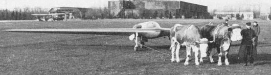
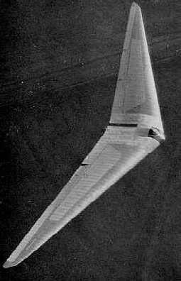
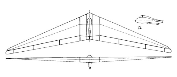
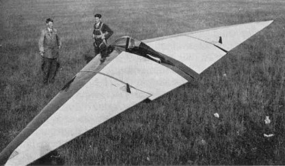
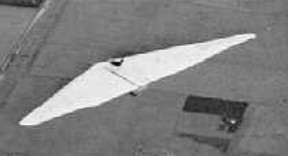
The span was the same as that of the H III but aspect ratio was increased from 10.7 to 21.1, and the control system further developed. In order to retain their finless wing layout and get the maximum aerodynamic efficiency, the pilot was put in a prone position with his body in a 27% thickness ratio egg and his knees and legs in a small leg well. The well also supported the rear skid (or wheel in the case of the H IVb). An example of the HIV was found at Göttingen in good condition and was brought back to R.A.E. for test flying. It has completed 500 hours flying since its construction in 1942, including a cloud flight of 1-hour on instruments; such a flight demonstrates that stability and control and the comfort of the prone position must be satisfactory.
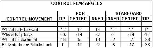
The three stage control flaps were all geared to the spectable type control wheel and operated on the same general principle as the earlier two flap control on the H III. The following table gives the (measured) flap movements corresponding to full control by the pilot.
It will be seen that the outer flap works principally as up going aileron whereas the “climbing elevator” action comes mainly from the middle flap and “diving elevator” action from the inner flap. Down going aileron, needed to neutralize pitching moments, comes from the inner and middle flaps together. The center and inner flaps were unbalanced, with round noses, the tip flaps Friese balanced with a skew hinge giving 39% balance at the inboard end and zero balance at the tip. This scheme gave the required aileron yawing moments without making the control flap at the tip vulnerable when a wing tip scraped the ground. Drag rudders were of the upper and lower surface spoiler type placed immediately ahead of the outer control flap; the upper surface spoiler had a vented web. To open the rudders the pilot had to press with his toes, moving the foot from the ankle against a spring loading on the pedals which gave “feel” to the control. By pressing both feet together he could open both rudders simultaneously, thus giving extra drag for glide control. Rudder operation was said to cause no buffeting of the control flaps. The movement transmission from the pilot’s pedal included a cam plate cut to give no rudder movement for negative movement of the pilot’s foot (i.e., pressure on the opposite pedal) and an approximately linear relationship between pedal movement and rudder projection for positive movement (i.e., pressure on the pedal). All controls were operated by push rods, the inner and central flaps and the drag rudders being moved by skew-hinge cantilevers. In the IVb the skew hinge principle was extended to the outer flap operation also. The method of operating the control flaps was simple to construct and eliminated all external control horns. Longitudinal trim was obtained by an internal bungee “spring” which can be adjusted to take any out-of-balance aerodynamic loads on the elevator control. There were no landing flaps by large spoiler type dive brakes were provided, which could be used to give variable drag for glide path control. The H IV used reflexed cambered sections (zero Cmo) of R.A.F. 34 type, changing to assymetrical section at the wing tip. The large wing dihedral of 5 percent was used to give adequate wing tip clearance. Reimar Horten considered that aerodynamically this might be on the large side but advisable for practical reasons. It should be remembered that both the H III and H IV have an abnormally low value for the lateral relative density Uso that unusual values of Lr and Nv would be permissible without dynamic instability resulting. Performance was measured by flying the H IV against the D 30, a conventional high performance glider which had been carefully performance tested by D.V.L. to form a “standard”. The essence of the method was to two both aircraft up together and let them glide down from about 10,000’ at a series of speeds, measuring the relative height photographically, at intervals. From these tests the best gliding angle of the H IV was found to be 1 to 37 and the minimum sinking speed 1.7 ft/sec. Minimum sinking speed was slightly less than the D 30, but at high speeds the d 30 was better. Scheidhauer, Horten’s chief test pilot, has done the majority of the flying in Horten IV’s (about 1000 hrs) and his comments are worth recording. He was a strong advocate of the prone position – in his own words “it has nothing but advantages.” All H IV controls he described as very light, he flew the glider with “two fingers”. The elevator was apparently rather sensitive compared with the aileron but not unpleasantly so. Aileron application produced no adverse yaw – a definite improvement after the II and III – and could reverse a 45 degree banked turn in 5 secs. at 70-90 mph, which is better than the average sailplane. Longitudinal stability he thought satisfactory but he commented on a “wiggle” which was produced by flying through gusts; this is apparently a sharper pitch response than for a conventional sailplane, but well damped, quite harmless and requiring no corrective action by the pilot. A true stall could not be produced with normal elevon adjustment because of increasing static stick fixed stability at the stall, which used up available elevator power before the wing tips were stalled. Spins could only be produced by applying full aileron and rudder with the stick hard back; recovery was easy. Stability and controllability on tow were excellent. Scheidhauer described a competition in which a number of sailplanes were aero-towed form Grunau through the very turbulent air in the “standing wave” from a nearby mountain; the rough air had to be negotiated on tow to get to the area of rising currents. All the instructors from the school at Grunau were flying conventional sailplanes and broke their two lines without exception. Scheidhauer in his H IV managed to get through and soar in the standing wave. He attributed his success partly to his own skill and partly to the good controls of the H IV plus his ability to use the tip rudders together to check surging in the tow rope. Take-off seems to present some problems to a pilot new to the aircraft. It seems that the short undercarriage base, responsive elevator and small wing tip clearance can produce a very erratic take-off if the pilot is not smooth and precise in his control movements. Construction followed the normal Horten practice, but the wing panels were made with detachable tips of sheet clektron. This was necessary because the narrow chord at the tip made accurate construction in wood very difficult. The center section was of welded steel tube, with perspex nose and a large jettisonable access cover behind the main spar. The front skid was retractable and fitted with a wheel which automatically dropped off as the skid retracted. The pilot’s harness was modified from the original version, being a single broad strap passing under the buttocks. This was released by the same handle that jettisoned the access cover. The pilot’s parachute was stowed in a pocket on the cover and connected to the pilots harness by short straps. In this was the pilot was relieved of the weight of the pack, which would otherwise have caused some discomfort on a long flight. Flying instruments included a low reading A.S.I. driven by a venturi, electrical turn and bank indicator, sensitive variometer, high reading variometer, altimeter and clock. Oxygen equipment comprised two bottles, pressure gauges, reducing valve and economizer, and provision was made for electrically heated clothing. Ventilation was under the pilot’s control. The pilot position could be adjusted for varying pilot size and a chin rest with adjustment for height was provided. The pilot was prevented from sliding forward by shoulder rests and the reaction of his thighs against the knee well. Comfort appeared to be satisfactory when we tried the bed but elbow and shoulder movement was restricted which constrained one to stay in the same position all the time.
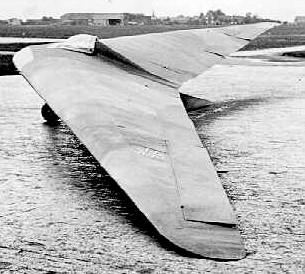
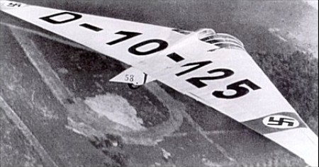
Superficially the IVb resembles the IV very closely but the aerodynamic changes were a fundamental experiment. The Hortens intended to produce a laminar flow sailplane with superlative high speed performance – in this they were partially successful but they sacrificed too much on the stability and control to make the venture a real success. Production had been started, prematurely, at the rate of about two a month. Wing sections were derived from the Mustang section which had been measured by D.V.L. for captured aircraft and tunnel tested. The Hortens were excited by the low tunnel drag figures and designed the H IVb to exploit them. The root section was the original Mustang profile, changing to an uncambered section with the same fairing shape but reduced thickness at the tip. Wing twist was reduced (compared with the IV) to 5.6 degrees to get the greatest spanwise extent of laminar flow, and sweepback reduced to 2 degrees to get the CG farther back relative to the mean chord (this was necessary because the aerodynamic center of the basic wing section was farther aft). It is interesting that although Cmo was not zero for the root section, the high aspec ratio enabled the glider to be designed to trim, elevons neutral, at the required top speed (140 mph) without needing excessive twist. The wing structure ahead of the main spar was a ply sandwich monocoque with Tronal filling. Tronal was an expanded wook with specific gravity 0.1 to 0.09, invented by a Dr. Barschfeld of Dynamit A.G., Troisdorf (near Cologne). The sandwich was made up on molds, with outer ply 1 mm thick and inner ply .8 mm; the filling was 20mm at the root tapering to 5 mm at the tip. The nose sections were stuck onto the front of the main spar with supporting ribs every 2 meters. Between the main and rear spars normal ply covering was used, insufficient Tronal being unavailable for sandwich construction all over. Waviness in a chordwise direction was not controlled or measured. Sag (spanwise) between ribs had been measured on the IV and eliminted on the IVb. Special care was taken to kep dust off the wings; wing dust covers were made and all handling was done with gloves on. Control circuit mechanism remained the same except for the outer flaps which were also operated by a skew hinge lever on the IVb. The dive brakes were moved back to the rear spar to suit the revised wing structure No transition measurements were made on the IVb, but it was flown against a calibrated IV and the following relative sinking speeds measured.
The change of section raised the stalling speed from 45 kph on the IV and to 60 kph on the IVb. The handling characteristics were very unsatisfactory. A wing tip stall occurred followed by wing dropping and spinning. The first aircraft crashed for this reason after the pilot got into trouble in a cloud. An attempt was made to improve matters on the second glider by clipping the span from 20.25 meters to 18.5 meters but results were disappointing. As a cure on the final design a reversion to the old H IV tip section was proposed, the theory being that section stalling characteristics were bad due to the sharp nose radius. Partial breakaway behind the maximum thickness point was suggested, aggravated by spanwise boundary layer drift which rendered the elevon ineffective. Horten thought the small wing tip Reynolds number made the use of low drag sections inadvisable.
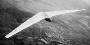
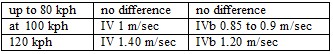
Professor Dezso George-Falvy of Mississippi State University in a German Horten Ho IV glider – one of two to survive the Second World War. (1960)
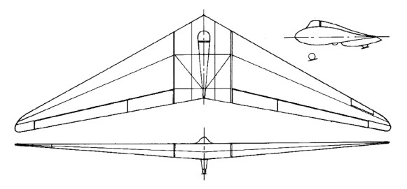
In 1938, with this official backing, the Hortens set up a facility at Berlin’s Tempelhof Airport, where they constructed the Ho III sailplane. The first H III was built at Templehof Berlin in 1938 and the second (H IIIb) was built by Peschke Flugzeugban, also in Berlin. The main change from H II were increase span (20 m), reduce sweepback (23degrees) and modified lateral controls. The outer wing panels this time had three movable flaps. The innermost was again a landing flap, but the outer pair were geared so that the outer flap had a large range of upward deflection and, only slight downward movement and, the inner flap large downward movement and slight upward movement. This arrangement reduced unfavorable yawing moments due to aileron by making use of differential aileron movement, but avoided the change in longitudinal trim by the opposing differential of the inner flap pair. In high speed flight the nose down trim was provided mainly by the inner elevon section moving downwards, the outer flap deflecting only slightly; this had the advantage of relieving the tips of torsional loads at high speed. Aerodynamic balance was again by geared tab on sub types IIIa and b, but on IIId, f, and g the outer flap had a 20% Friese nose: out of balance aerodynamic loads on the elevators were trimmed by a rubber bungee trimmer.
Ho.IIId
Drag rudder design remained the same as for the H II.
The H III seems to have been a successful and useful type, for 14 were built altogether and several different sub-types developed. Production of some of the sub-types was still going on in 1945. The following variations on the original theme were produced:
IIIa – Original design
IIIb – Similar, but with outer elevon flap not extending to the wing tip.
IIIc –
Same as IIIa but with a fixed front plane. One of these was built, for the 1938 Rhon contest. Very little flying experience was obtained. The idea was to improve CLmax.
IIId – Standard wings fitted to a special center section with 32 hp Volkswagen engine and folding propeller. The idea was to produce a high performance sailplane with auxiliary engine for takeoff and climb, which could be shut off for soaring without impairing the performance as a sailplane. Center sections (Opel engine with gear drive) were being produced at Tubingen at the rate of two a month. 12 partly finished were in the workshop in June 1945. Finished parts were sent to the Wornberg and assembled with wings made at Darnsdorf. Performance with power was stated to be: Ground run: 70 meters Rate of climb: 2 m/sec. Cruising speed: 110 kph Max. speed: 130 kph The engine installation was take straight from the Volkswagen complete with exhaust system and electric starter; it weighed 240 lbs.
IIIe – H III glider with waggle tips. On this aircraft, remains of which were found at Gottingen, the tips were operated directly by the pilot.
IIIf –
Same as the IIIb, but with prone position for the pilot. A specimen of this type was found at Gut Nierstein with modified controls. The outer flap had a Frise nose, (as on H IV), spoiler type drag rudders were fitted in place of the usual leading edge split flaps, and H IV type dive brakes installed. The prone piloting position eliminated the need for the head fairing used on the other H III’s and gave the pilot a much better view.
IIIg – Special two-seater center section with tandem seats. Specimens were found at Zimmern and Hernberg. This type was used for training purposes.
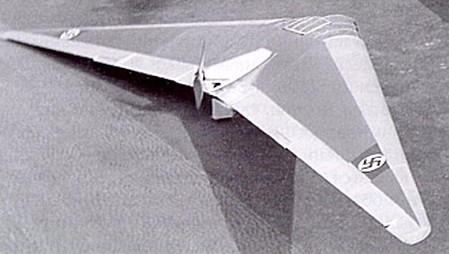
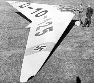
H IIIh / Ho-229 – One built in 1944.
No independent opinions are available on the flying qualities of the H III series, but Reimar Horten was insistent that it was a very straightforward aircraft from the pilots point of view. He stated that any glider pilot with five hours experience could be safely sent off solo in an H III.
Horten H III a Wing span: 20.4m Wing area: 36sq.m Empty Weight: 220kg Payload: 80kg Gross Weight: 300kg Wing Load: 8.3kg/sq.m Aspect ratio: 11.6 L/DMax: 28 60 kph MinSink: 0.48 m/s 45 kph Seats: 1
Horten H III c Wing span: 20.4m Wing area: 36sq.m Empty Weight: 220kg Payload: 80kg Gross Weight: 300kg Wing Load: 8.3kg/sq.m Aspect ratio: 11.6 L/DMax: 28 60 kph MinSink: 0.48 m/s 45 kph Seats: 1
Horten H III f Wing span: 20.5m Wing area: 37.5sq.m Empty Weight: 280kg Payload: 80kg Gross Weight: 360kg Wing Load: 9.6kg/sq.m Aspect ratio: 11.1 L/DMax: 28 63 kph MinSink: 0.52 m/s 47 kph Seats: 1
H IIIh Wingspan 54 ft. Length 16.4 ft. Height 5.4 ft. Empty weight 586 lb Loaded weight 807 lb Wing area 344 sq. ft. Wing loading 2.25 lb/sq. ft. Glide ratio 24:1 Aspect ratio 8.48 Max speed 143 mph Best glide 45 mph
The Horton Ho.2 was of the same general layout as the H I but with sweepback increased from 19 degrees to 26 degrees and the lateral and longitudinal control combined in an elevon. Inboard flaps extending from elevon to center section were used to increase maximum lift and drag for landing. The first version was completed as a glider and the second fitted with a 60kW / 80 hp Hirth engine driving a pusher propeller in 1935. In this aircraft the pilot was seated in a reclining position and completely contained in the wing contour; a maximum level speed of 210 kph was achieved. This was tested in 1938 by Hanna Reitsch and attracted the attention of Ernst Udet, Director of the Technical Department of the German Air Ministry, who made funds available for further development.
Subsequently there more gliders were built, the last being completed in 1937 after which the type was abandoned in favor of the H III. The root wing section was change from the 20% symmetrical H I type, to a 20% section with reflexed camberline (zero Cmo) changing along the span to a symmetrical tip section. A balance tab was fitted to lighten the controls which were all pushrod operated. The structure was in three parts, as in all subsequent Horten designs. The center section being the welded tube and the outer panels of wood with a D-nose spar. The wheel undercarriage had brakes and the front wheel was retractable. Drag rudders consisted of lending edge flaps (as on the Horten III) opening against a spring.
From a translation of Hanna Reitsch’s report on one of the H II gliders, it is clear that lateral and directional control were still only partially satisfactory although characteristics at the stall were excellent. This feature is remarkable, for although a wing twist of 8 degrees was used the effect of the high taper and sweepback might be expected to overpower the beneficial effect of twist in delaying the tip stall.
Reimar and Walter Horten started out with models, then progressing to gliders and eventually to powered aircraft. Their first tailless design, the Ho I sailplane. This was built at Bonn during the year 1931-1932 and had a flying life of about 7 hours. It had a span of 40 ft. and a wing loading of 2 lb/sq.ft. The control system comprised a control flap giving elevator control and normal ailerons at the wing tip. Directional control was by leading edge drag rudder at the wing tip. All the control flaps were hinged at the upper surface with a circular arc lower leading edge forming a seal with the wing. There was no aerodynamic balance. The wing section was symmetrical throughout and thick enough (25% C) at the center section to house most of the pilots body. His head projected from the upper surface and was faired by a perspex cockpit cover. A rubber mounted skid formed the undercarriage. The control system was unsatisfactory and was changed on subsequent aircraft. It seems to have been impossible to stop a slow speed turn by use of ailerons alone and the drag rudder, which at first was on the lower surface only, was ineffective and caused a nose down pitching moment. When an upper surface flap was added to cure this the braking action became too fierce and springs had to be incorporated to make the control heavier. Reference was made to a yawing tendency at low speed which could result in an uncontrollable turn through 360°. The Ho I sailplane, won a prize at the 1934 Rhon soaring competitions, but the brothers were not satisfied with its performance and burned it.
Walter and Reimar Horten conducted flying-wing experiments prewar, building a series of tailless high-performance gliders. The Horten Ho V and Ho VI were both powered aircraft, leading to the turbojet-powered Ho IX flown in the summer of 1944. Before being destroyed in a landing accident after only a few hours flight, it had been flown at a speed of 800km/h. This was developed by Gothaer Waggonfabrik as the Gotha Go 229 V3 single-seat fighter, but the Gothaer works were captured by advancing U.S. forces before this prototype was completed.
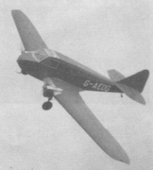
The Hordern-Richmond Autoplane, G-AEOG, was built at Heston in 1936 by the Heston Aircraft Company Ltd. A three seater powered by two Continental A40s, it was scrapped during WW2.
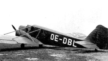
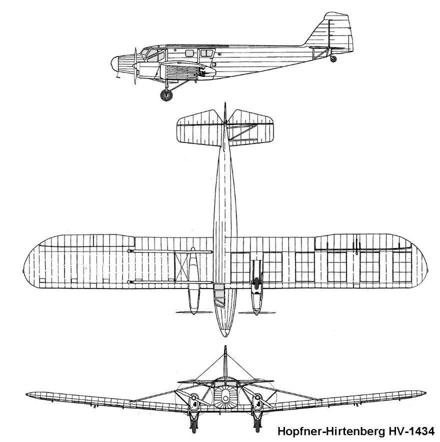
After the development of the transport high-level plan HV.12 / 34, designer Lampich started the design of the low-wing transport aircraft, designated Hopfner HR.14/34 (HR.1434) Werk.Nr 33. Despite not some similarity, it was a completely unique project. The only example of the aircraft was built by Flugzeugbau Hopfner GmbH at the Aspern Vienna airfield.
The retractable undercarriage was later modified as fixed.
The first flight of the aircraft prototype (registration number OE-DBL, D-OBDL later) took place on March 24, 1936. The aircraft was used (mainly for advertising purposes) until the spring of 1937.
Engine: 2 x de Havilland Gipsy Major, 120 hp Wing span: 20.10 m Wing area: 48.00 sq.m Length: 11.77 m Height: 2.84 m Empty weight: 1754 kg Normal take-off weight: 2300 kg Maximum speed: 139 km / h Cruise speed: 108 km / h Service ceiling: 3166 m Crew: 1-2 Passenger capacity: 5
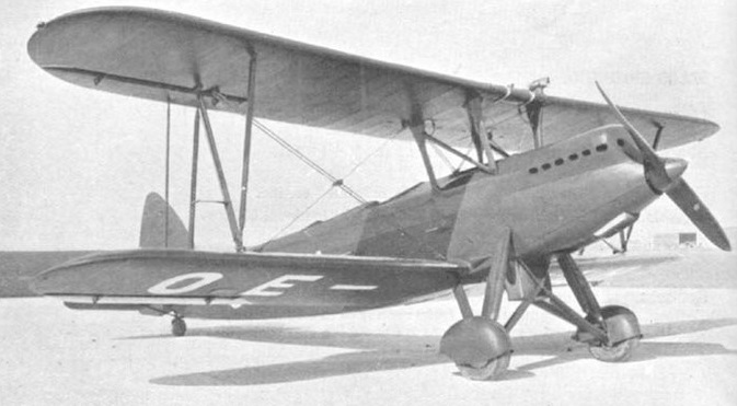
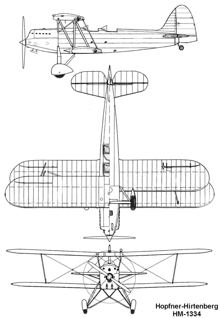
In 1934 Flugzeugbau Hopfner GmbH began building the Hopfner HM.1334 (HM.13/34). This was done on a purely private basis because there was no corresponding request from the Austrian Air Force.
The machine was a two-seat, single-engine biplane in mixed construction with fixed tail wheel gear and normal tail. The fuselage consisted of a tubular steel structure covered with plywood and fabric around the stern. Only in the engine area were light metal sheets used.
The two open pilot seats were arranged one behind the other and had sloped windshields. As engine only a BMW VI with 750 HP was to be used, but there were procurement problems, so that Lampich had to resort to available Fiat A-20 series engines. As armament was a 7.9 mm machine gun Hotchkiss provided, installed in the upper wing and firing over the propeller circle. The biplane wings and the tail were wooden structures covered with plywood and fabric. All control surfaces were cloth-covered. The upper wing had a short wing center piece, which rested on each of two V-struts above the fuselage. The upper and lower wings were each connected by an N-strut and additionally with cables. The tailplane was supported by a strut to the fuselage. The undercarriage was on the engine frame of the fuselage and also backwards to the fuselage and the hull bottom. The wheel arches were aerodynamically shaped.
With the takeover of Hopfner by the Hirtenberger Patronen-, Zündhütchen- and Metallwarenfabrik AG in Hirtenberg, the semi-finished aircraft was brought to Hirtenberg, where it was completed in 1935 and received the designation HM.13/34 or HM.1334.
The first flight took place on June 6, 1935 and during the following flight testing there were no noteworthy incidents. The machine was then presented to the Austrian Air Force, but the interest was low, since several Fw 44J had been procured from Germany for fighter pilot training.
Finally, at the beginning of 1936, three machines were ordered by the Austrian Air Force (for Verwendungsgruppe B, Beanspruchungsgruppe II), which were delivered from the summer of 1936 and received the civil identifiers OE-FAH (factory number 52), OE-FEH (factory number 53) and OE-FIH (factory number 54). After the annexation of Austria to the German Reich in 1938, the three machines, like all Austrian military machines, were taken over by the Luftwaffe and passed on to fighter pilot schools in southern Germany.
The fate of HM.13/34 is unknown.
Hopfner / Hirtenberg HM.13/34 Engine: Fiat A-20, 410 hp (302 kW) max / Continuous power: 355 hp (282 kW) at 3,000 m Propeller: adjustable two-bladed wood Propeller diameter: 2.50 m Propeller disc: 4.91 m² Wingspan upper: 10.21 m Wingspan lower: 9,60 m Upper wing dihedral: 2.33° Lower wing dihedral: 2.66° Wing area: 27.80 m² Aspect ratio: 6.76 Wing chord: 1.08 m Length: 8,45 m Height: 3,03 m Empty weight: 1,185 kg Normal weight: 1,585 kg Maximum TOW: 1,695 kg Fuel tank capacity: 345 lt Top speed SL: 258 km / h Top speed at 3,000 m: 272 km / h Cruise speed at 3,000 m: 245 km / h Landing speed: 96 km / h Ceiling: 6,000 m Climb rate: 7.3 m / s Time to 1,000 m: 2,4 min Time to 3,000 m: 9.5 min Range normal: 450 km Maximum range: 600 km Endurance: 2.5 hr Wing loading: 60.97 kg / m² Power load: 4.13 kg / hp (5.61 kg / kW) Wheel track: 2,54 m Crew: 1 Armament: 1 x 7.9 mm Hotchkiss machine gun / 500 rounds Maximum bomb load: 40 kg
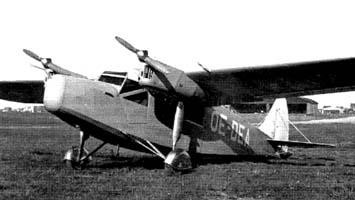
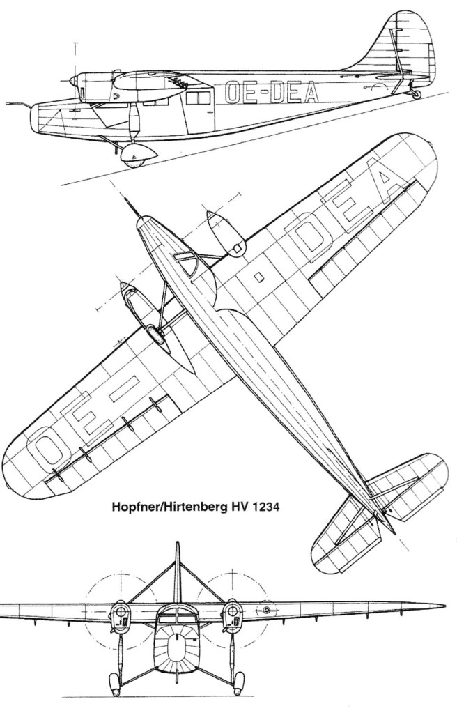
The Hopfner HV.12 / 34 (HV.1234) light transport aircraft was designed by Lampich by special order of Anton von Habsburg, Prince Lorraine. The aircraft became the first twin-engine transport aircraft of Flugzeugbau Hopfner GmbH.
The HV.1234 featured six-seat., with enclosed cockpits and fixed undercarriage. The spacious fuselage was a steel tube construction, which was covered with fabric in the front and back center area with plywood at the stern. The passenger cabin space offered seats for five passengers and was luxuriously equipped. The two spar wings and tail were wooden structures, which were covered with plywood and fabric. The rudder were fabric covered. The flanding gear was fixed to the wing spars, and went through the engine cowling and had two oil dampers. Against the bottom of the fuselage, it was connected, each with a V-strut.
The first flight of the prototype aircraft, registered A-150 werk.Nr 28, took place in August 1935 at Aspern. The flight characteristics were assessed as good and the HV.12/34 flew irregularly as a private aircraft, but also as a light transport aircraft.
The following year, the aircraft received the registration number OE-DEA. After the annexation of Austria in 1938, the registration number was changed to D-OEEA. Later it came to the Airborne Division of Hirtenberger Cartridge Factory AG. When war broke out, it should be used as a liaison aircraft for the Luftwaffe, but there were problems with the supply of spare parts for the engines and the HV.12/34 was taken out of service. The fate is unknown.
Only the one was built.
Engine: 2 x de Havilland Gipsy Major, 130 hp Prop dia: 2.00 m Prop disc: 3.14 sq.m Wing span: 14.10 m Wing area: 30.00 sq.m Aspect ratio: 6.63 Dihedral: 1 deg Length: 10. 40 m Height: 2.70 m Empty weight: 1100 kg Normal take-off weight: 2000 kg Max take off weight: 2160 kg Fuel capacity: 210 lt Maximum speed: 205 km / h Maximum speed at SL: 186 km/h Cruising speed: 175 km / h Range: 950 km Servce ceiling: 4800 m Climb to 1000 m: 6.25 min Climb to 3000 m: 25 min Rate of climb: 2.8 m/sec. Endurance: 6 hr Crew: 1 Passengers: 5