Klemm-Daimler-Leichtflugzeug L20 / Aeromarine Boland L-20

Klemm-Daimler L20

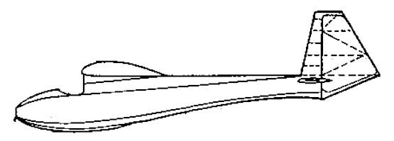
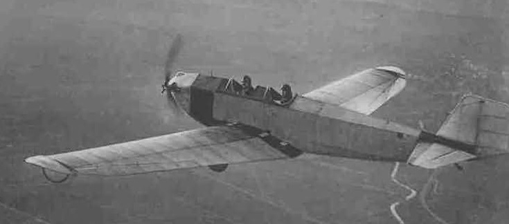
Hans Klemm’s first light aircraft was the Daimler L15 and the L20 had much in common with it. Both were cantilever monoplanes with twin open, tandem cockpits and engines of very low power. The L20’s low wing distinguished it from its predecessor and had the advantage of providing a low centre of gravity and better view during the landing approach as well as better protection for occupants in case of crash landings. The low-set wing also allowed a shorter undercarriage on the L20, which was otherwise like that of the L15 with the wheels independently mounted on pairs of centrally hinged V-struts and with vertical shock absorbing legs to the wing underside. Wheels were sometimes replaced by floats. Intended from the start for serial production, the L20’s structure was simplified, with a pentagonal cross-section fuselage lacking the L15’s rounded upper and lower surfaces. The fuselage was wooden framed with canvas covering. The overall strength of the structure, which had a safety factor of 12, was emphasised.

The wing was tapered in planform and was built around two spars, though there were two variants of the internal wing structure. The first three aircraft, type L20 A1, had wings stiffened against torsion by internal wire bracing but later aircraft, type L20 B1, used a torsion box formed by plywood skin ahead of the rear spar. Like the later version of the L15, the L20 used a combination of conventional ailerons and unusual wingtip flaps, rotating about an axis well ahead of mid-chord.

Wingtip, aileron-linked “flap” on early L20

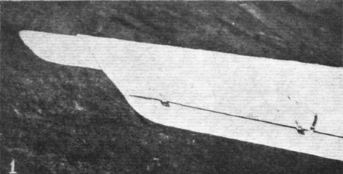
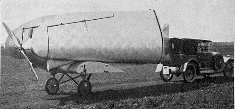
The ailerons were directly controlled from the cockpit as normal and the tip flaps were linked to them with external rods and cranks. On early examples these flaps were roughly square, with a side less than a half of the chord at the tip, but at some later time they were reshaped to produce wing curved tips. The wings could be detached at the root in about five minutes, reducing the width of the L20 to 1.7 m (67 in) for road transport on a trailer pulled by a car.

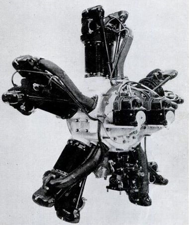
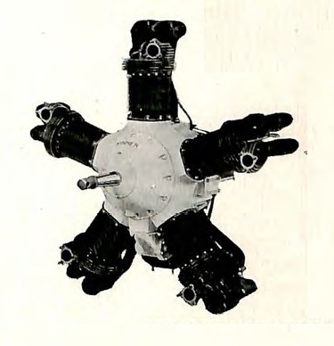
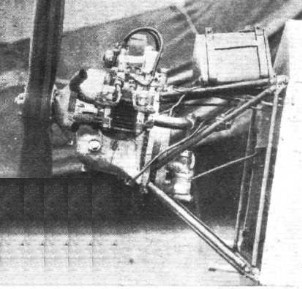
At the beginning of the design and testing period the absence of a suitable, serially produced light aircraft engine was a concern and the wing was therefore mounted so that it could be moved fore and aft to allow for the varying centre of gravity positions resulting from engines of different weight. A glider version was contemplated though not finally used. Instead, the flight programme began with the L20 powered by the 9 kW (12.5 hp) Harley-Davidson motor cycle engine used in the L15. By mid-1925 this had been replaced with a new engine, the 15 kW (20 hp) air-cooled, flat twin Mercedes F7502a, which Klemm had persuaded Daimler’s engine group to design and build for the light aircraft market. The cost of flying the L20 was low as its cruise fuel consumption was only 63 mL/km (45 mpg). From 1926 the uprated 15 kW (20 hp) Mercedes F7502b was fitted. The F7502 was central to the success of the L20, though it suffered from repeated rocker arm failures.

The Mercedes F7502 engine installation

Having failed to persuade the Daimler management to undertake series production of the L20 despite its early successes, in 1927 Klemm left to set up his own company, Klemm Light Aircraft in Sindelfingen, later moving to Böblingen. Thereafter the L20 was often known as the Klemm-Daimler L20 or sometimes the Daimler-Klemm L20.

The 1925 Round Germany Flight involved five circuits over a total distance of 5,262 km (3,270 mi). Two early L20s and the twin-engined L21 competed against many aircraft from other German manufacturers. All three Daimler aircraft were very successful in the under 40 hp (30 kW) class, with the L21 the overall winner, receiving 25,000 Goldmarks (worth £1,250 in 1925) and the two L20’s coming second and third and winning another 25,000 Goldmark between them. They also contributed to the award of first prize in the contest between German engined aircraft to Mercedes.

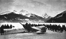
The best known and most significant flight by the L20 was the wintertime crossing of the Alps in early 1926. Flight Magazine hailed this as the “Vindication of the Light ‘Plane”, in the sense that it showed small aircraft to be a practical vehicle for travel over difficult terrain and in uncertain weather. The pilot was Guritzer and the navigator/engineer von Lansdorff, both from Daimler. The flight began at Daimler’s Sindelfingen base on 16 February. No special preparation such as fuel dumps were made in advance and carefully prepared maps were lost overboard early in the flight. The weather frustrated several attempts to cross the Alps but at last the L20 landed in 300 mm (1 ft) of snow near Zeller See. The return journey reached eastwards, skirting the Alps via Budapest and Vienna and arriving home at Sindelfingen on 16 March.

L 20 at Zeller See after crossing the Alps in winter

During 1927 the L20 continued to contest competitions such as the Lilienthal Prize, winning most of the prizes in the lightplane class and making overseas visits such as the one to the UK in July. Private owners also took them on long tours, such as the 1927 North European flights of Anton Riediger but no-one went further with their L20 than Baron Freidrich Carl von König-Warthausen, who set off on 11 August 1928 on a world tour, beginning with a flight to Moscow, then on to Tehran, Calcutta and Singapore. From there he and the L20 crossed to North America by sea but flew across the United States, arriving in New York City on 3 September 1929 after travelling 36,000 km (22,369 mi) from Berlin.

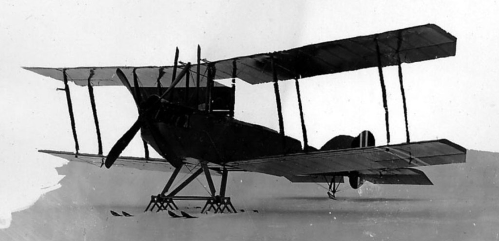
One L-20 was built in 1928 by Aeromarine for evaluation. Others registered under the Klemm title, eg: N4919 and N4920, with Mercedes motors, are probably German imports of an earlier date.

The Klemm L25 was evolved from the all-wooden construction Klemm-Daimler-Leichtflugzeug L20 from 1924.

Klemm-Daimler-Leichtflugzeug L20
Engine: 1 × Mercedes F7502a 885 cc, air-cooled flat twin, 15 kW (20 hp) 20 PS
Propeller: 2-bladed
Wingspan: 13.0 m (42 ft 8 in)
Wing area: 20.0 sq.m (215 sq ft)
Empty weight: 265 kg (584 lb)
Gross weight: 450 kg (992 lb)
Wing loading: 22.5 kg/sq.m (4.60 lb/sq.ft)
Power loading: 30 kg/kW (50 lb/hp)
Maximum speed: 105 km/h (65 mph; 57 kn)
Range: 480 km (298 mi; 259 nmi)
Service ceiling: 4,100 m (13,500 ft)
Time to altitude: 12.6 min to 1,000 m (3,281 ft)
Landing speed: 42 km/h (26 mph)
Crew: two

Aeromarine Boland L-20
Engine: Mercedes, 20 hp
Wing span: 38 ft 0 in
Max speed: 80 mph
Cruise speed: 66 mph
Stall speed: 20 mph
Seats: 2

Klemm

Dr Ing Hanns Klemm (1885-1961) was an eminent pioneer in the development of light aircraft. During the First World War he worked with Zeppelin, Dornier and Hansa und Brandenburgische Flugzeugwerke, and later with Daimler, for whom he designed biplanes and monoplanes, including fighters. After the war he concentrated on light and economical aircraft, sometimes called Daimler-Klemm. L15 of 1919 was originally a glider, though later powered, but had high wing. True precursor of the classic Klemm low-powered two-seat line of low-wing monoplanes was L20 of 1924. In December 1926 Leichtflugzeugbau Klemm GmbH was formed (notably associated with Bb’blingen), and L 25 was produced from 1927 with many types of engine, consolidating Klemm’s reputation. K131 and K132 of early 1930s were cabin types. Part of Klemm became Halle in 1934. Company renamed Hans Klemm Flugzeugbau August 1938, and was then making K135 cranked-wing tourer/trainer series for Luftwaffe and export. In new type-number series built Kl 105-107. During Second World War contributed to military-aircraft production, afterwards Klemm revived Kl 107 three-seat cabin model. Klemm joined Siebel in 1940.
Production ended November 1957.

Kjeller Flyfabrikk / Kjeller Flyvernaskinsfabrik

Lillestrømmen Aeroplanværksted (Lillestrøm Airplane Workshop)
Hærens Flyvemaskinfabrik (Army Flying Machine Factory)

This state-owned factory was established in 1914 at Kjeller airfield at Lillestrøm north of Kristiania (Oslo). The original name was Lillestrømmen Aeroplanværksted (Lillestrøm Airplane Workshop), in 1915 it become the Hærens Flyvemaskinfabrik (Army Flying Machine Factory) which had relocated from Sagene in Kristiania.
The name Kjeller Flyfabrikk didn’t appear until Aug 1927.

The Norwegian Army Aircraft Factory, located at Kjeller. Built under license during the 1930s Fokker C.V as the F.F.7 Hauk (Hawk) and de Havilland Gipsy Moth and Tiger Moth. Also did repair and overhaul of military-aircraft equipment, and experimental work.

Kirkham, Chas. B

Chas. B Kirkham (1882-1969) was a friend and collaborator of Glenn Curtiss. He made motorcycle engines from about 1900, and in 1910 an aero engine. In 1915 he joined Curtiss in engine work and is chiefly known in connection with the famous D-12. Wanting a fighter worthy of his K-12 engine, with its small frontal area, Kirkham planned a two-seat triplane with excellent streamlining, first flown July 5,1918. To this record-breaker the name Kirkham Fighter, 18-T or Curtiss-Kirkham was applied, though the Curtiss name alone was later used for land and sea versions. U.S. Army had 18-B biplane equivalent, also sometimes called Curtiss-Kirkham. Navy’s two 18-Ts were later adapted for racing. In 1920s Kirkham’s company Kirkham Products designed aircraft to special order.

Kinner R-715

The R-715 can be installed as tractor or pusher. The standard starter mount affords a wide range of starters, as Heywood injection, hand turning gear, electric or combination starters, electric starters etc. The provision of a standard drive for an electric starter affords use of electric type starters, lighting system, radio etc. Provision of a fuel pump drive allows various locations of fuel tanks. The carburettor location allows gravity feed. Standard SAE propeller end of crankshaft provides for use of a minimum weight metal propeller hub.

Type: 5 cylinder 4 stroke air cooled radial
Manufacturer’s Rating: 190 hp at 1800 rpm
Displacement: 715 cu.in
Compression ratio:
Bore: 5 5/8 in
Stroke: 5 3/4 in
Length: 34 13/16 in
Diameter: 50 in
Weight: 410 lb
Lubrication: Circulating oil system, pressure feed to front & rear main bearings, and to plain link pins, through grooved master rod bearings.
Ignition: 2 Scintilla magnetos
Carburation: Stromberg

Kinner R-5 / R-53 / R-55 / R-56 / R-540

Kinner R-56 installed in a PT-22 Recruit

The Kinner R-5 is an American five cylinder radial engine for light general and sport aircraft of the 1930s. The R-5 was a development of the earlier Kinner B-5, with slightly greater power and dimensions. The main change was the increase in cylinder bore from 117 mm (4.625 in) to 127 mm (5 in) and an increase in cylinder stroke from 133.3 mm (5.25 in) to 139.7 mm (5.5 in). This led to a corresponding increase in displacement from 7.2 liters (441 cu in) to 8.8 liters (540 cu in).

The head of the R-5 Series 2 has approximately three times as much cooling fin area as previously used cylinder heads, having longer fins spaced closer together. A greater angle between inlet and exhaust valves results in a stronger head and provides additional metal between valve seats. Cylinder heads have rear exhaust ports and lugs are provided for support of cowling rings.

Enlarged intake passages and valves increase the efficiency and result in higher brake mean effective pressure.
Bearings have been increased in size. The crankshaft has been greatly strengthened by increased sections. The main and master rod bearings are of the copper lead steel-backed type. Master-rod sections have been enlarged and design altered to give a very much stronger rod with little increase in weight. Improved front cover provides additional strength and durability. All oil passages are contained in the engine.

Kinner R-5 Series 2

Rocker arms have a roller supported on needle bearings on valve end which reduces side thrust on valve and increases life of valve guides. High pressure grease lubrication is provided for the main roller bearing of the rocker arm and the rocker arm end of pushrods. Pushrod rocker arm adjusting screws are designed so that with their removal the pushrod can be withdrawn through the opening of the rocker arm for inspection.

The Kinner R-5 Series 2 employs a separate camshaft for each of the five cylinders. Each camshaft includes a simple spur gear driven by pinion gear on rear end of crankshaft at one-half engine speed.

Spur type magneto drive gears are driven by the cam gears. Oil pressure and scavenger pumps are driven by shafts keyed into slots in the ends numbers three and four camshafts, respectively.

Provision for Eclipse compressed air started and Eclipse Y150 direct electric starter, also generator and fuel pump drives are provided. Each accessory has its own mounting pad. Provision is made in oil sump for Cuno oil filter.

This engne may be fitted with battery ignition and two machine gun synchronising drives were available.
The R-5 was a rough running but reliable engine and the R-5 and its derivatives were produced in the 1,000s, powering many World War II trainer aircraft, its military designation R-540.

Kinner R-5 160hp

Applications:
Kinner Sportwing
Kinner Playboy
Meyers OTW
N2T Tutor
Ryan PT-22 Recruit

Variants:
R-5
R-53
R-55
R-56

Specifications:
Kinner R-5
Type: 5-cylinder air cooled radial
Bore: 5 in (127 mm)
Stroke: 5 1⁄2in (139.7 mm)
Displacement: 540cu in (8.85 L)
Length: 32.3in (820.4 mm)
Height: 45.6in (1,157 mm)
Dry weight: 330lb (149.6 kg)
Valvetrain: 1 inlet and 1 exhaust valve per cylinder
Fuel system: 1 Stromberg carburetor
Fuel type: 73 octane
Oil system: Dry sump
Cooling system: Air
Power output: 160hp at 1,850 RPM max/113hp at 1,800 RPM cruise
Compression ratio: 5.50:1
Power-to-weight ratio: 0.48 hp/lb

Kinner R-5 Series 2
Cylinders: 5 radial
Bore: 5 in
Stroke: 5.5 in
Displacement: 540 cu.in
Power: 160 hp at 1850 rpm
Weight: 325 lb
Compression: 5.5-1
Ignition: 2 x Scintilla Magneto
Carburettor: Stromberg NA-R6
Crankshaft Prop end: No.1 SAE Standard

Kinner C-5 / R-720

The Kinner C-5 was an American five cylinder radial engine for small general and sport aircraft of the 1930s. The C-5 was a development of the earlier R-5 with greater power and dimensions. The main change was the increase in cylinder bore from 128 mm (5.0 in) to 143 mm (5.625 in) and an increase in cylinder stroke from 140 mm (5.5 in) to 145 mm (5.75 in). This led to a corresponding increase in displacement from 8.85 liters (540 cu in) to 11.71 liters (715 cu in).

The U.S. military designation was R-720.

Applications:
Consolidated YPT-11B
Kellett K-3
Kinner P
Stearman YPT-9C
Verville YPT-10D
Waco OSO
Waco OEC
Waco ODC
Waco OBF

Specifications:
Type: 5-cylinder air cooled radial
Bore: 5.625 in (143 mm)
Stroke: 5.75 in (145 mm)
Displacement: 715 cu in (11.71 liters)
Length: 34.8in (884 mm)
Diameter: 50 in (1,270 mm)
Dry weight: (dry) 420 lb (190 kg)
Valvetrain: 1 inlet and 1 exhaust valve per cylinder
Fuel system: 1 Stromberg carburetor
Fuel type: 73 octane
Cooling system: Air
Power output: maximum 245 hp at 2,200 rpm , cruise 210 hp at 1,900 rpm
Compression ratio: 5.25:1
Specific fuel consumption: 0.6 lb (273 gm) /hp/hr
Oil consumption: 0.015 lb (7 gm) /hp/hr