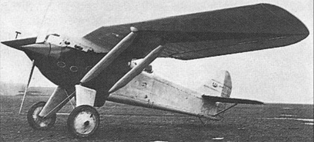
The installation of a radial engine in the P.Z.L. P.7 diminished the forward view for the pilot that was achieved in the P.Z.L. P.1 with its narrower V-12 engine, and it was proposed to improve this situation by the introduction of a Bristol Mercury radial engine, which was of smaller diameter than the Jupiter that powered the P.Z.L. P.7a.
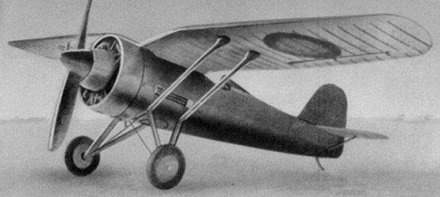
This version of the fighter was designated P.Z.L. P.11, but delay in delivery of a Mercury engine from Bristol resulted in the P.11/1 prototype being flown initially, in August 1931, with a 384kW Jupiter IX.ASb engine licence-built by Gnome-Rhone. It was not until December 1931 that the P.11/II was flown with a 395kW Bristol Mercury IV.A enclosed in a long-chord Townend ring. This prototype was later re-engined with a 373kW Gnome-Rhone 9K Mistral engine, with which powerplant it was exhibited at the 1932 Paris Salon de I’Aeronautique.
A third aircraft with a Mercury engine, the P.11/III, served as a pre-production prototype and, following satisfactory official testing, was approved for production for the Polish air force as the P. 11a. However, it was preceded on the production line by 50 Mistral-powered P.11b aircraft for Romania, all of them delivered by the summer of 1934. Production of the P.11a began with a batch of 30, these being similar to late-production P.11b aircraft, but differed by having the 386kW Skoda-built Mercury IV.S2 engine.
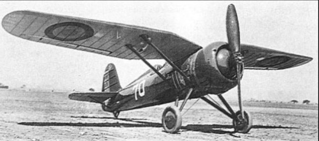
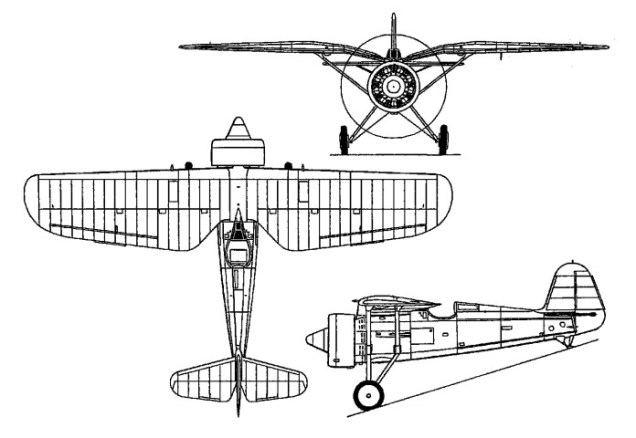
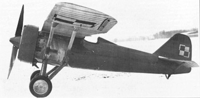
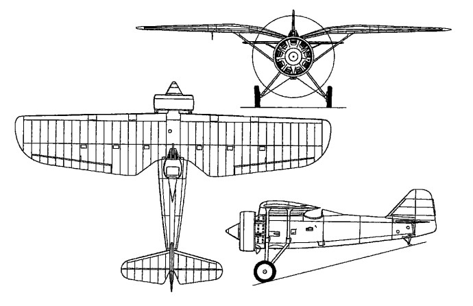
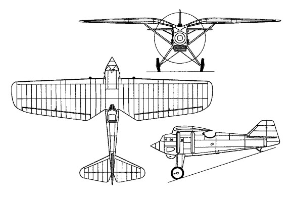
The major production variant was the P.11c which adopted more radical measures to improve the pilot’s field of view, lowering the engine and resitting the pilot farther to the rear on a raised seat, and a number of other improvements were incorporated at the same time. Production of this version totalled 175, the first batch being powered by the 418kW Skoda-built Mercury V.S2, but the remainder by the P.Z.L.-built Mercury VI.S2. A version of the P.11c, powered by a licence-built 9K Mistral engine, was built under licence in Romania by I.A.R. under the designation P.11f, about 80 being produced during 1936-38. Deliveries of the P.11c to Polish fighter squadrons were completed by the end of 1936, and at the outbreak of World War II 12 squadrons were equipped with the type, claiming the destruction of 126 Luftwaffe aircraft for the loss of 114 of their own number. When, in early 1939, it became clear that the planned P.Z.L. P.50 Jastrzab fighter was unlikely to materialise, efforts were made to provide the P.11c with greater capability by the installation of a 626kW licence-built Mercury VIlla engine and four-gun armament. A prototype was flown as the P.11g Kobuz and quantity production was initiated, but the German invasion of Poland, had started before any of these aircraft were delivered.
P-11c Engine: 1 x Bristol Mercury VI.S2, 481kW Wingspan: 10.72 m / 35 ft 2 in Length: 7.55 m / 25 ft 9 in Height: 2.85 m / 9 ft 4 in Wing area: 17.9 sq.m / 192.67 sq ft Max take-off weight: 1630 kg / 3594 lb Empty weight: 1147 kg / 2529 lb Max. speed: 390 km/h / 242 mph Ceiling: 8000 m / 26250 ft Range: 700 km / 435 miles Crew: 1 Armament: 2 x 7.7mm machine-guns, bombs
The P.8 represented an attempt on the part of Zygmunt Pulawski and his assistant, Wsiewolod Jakimiuk, to establish new standards in aerodynamic cleanliness and fighter performance. It combined a wing that was fundamentally similar to that of the P.6 and P.7 with a liquid-cooled engine and a new fuselage of improved fineness ratio covered by smooth duralumin skinning. Armament comprised the standard twin 7.92mm machine guns. The first prototype was destroyed in an accident in July 1932 at Innsbruck, and the P.8/II was displayed some months afterwards at the 1932 Paris Salon, but development had already been discontinued in favour of the radial-engined P.11.
PZL P.8/II Empty weight: 1102 kg / 2430 lb Wingspan: 10.50 m / 34 ft 5 in Length: 7.56 m / 25 ft 10 in Height: 2.75 m / 9 ft 0 in Wing area: 18.00 sq.m / 193.75 sq ft Max. speed: 350 km/h / 217 mph Range: 500 km / 311 miles
A parallel development to the P.6, from which it differed essentially in having a higher-altitude engine and some steel elements in the otherwise all-duralumin fuselage structure, the P.7 was powered by a supercharged Bristol Jupiter VII.F radial affording 520hp at 3050m.
The first of two prototypes, the P.7/I, was flown in October 1930, and featured a close-fitting, helmeted engine cowling, which gave place to a Townend ring on the P.7/II.
Work on a pre-series batch of 10 of the P.7a fighters began in June 1931 for the Lotnictwo Wojskowe, a further 139 being subsequently ordered.
The P.7a carried two 7.92mm Vickers “E” machine guns and differed from the prototypes in having a P.Z.L.-developed ring cowling, a revised cockpit, shorter ailerons and modified tail surfaces.
The P.7a entered service in the winter of 1932-33, and three first line squadrons were still equipped with this type when the Wehrmacht assault on Poland was launched on 1 September 1939.
Max take-off weight: 1476 kg / 3254 lb Empty weight: 1090 kg / 2403 lb Wingspan: 10.57 m / 35 ft 8 in Length: 6.98 m / 23 ft 11 in Height: 2.69 m / 9 ft 10 in Wing area: 17.90 sq.m / 192.67 sq ft Max. speed: 327 km/h / 203 mph Range: 600 km / 373 miles
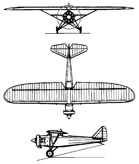
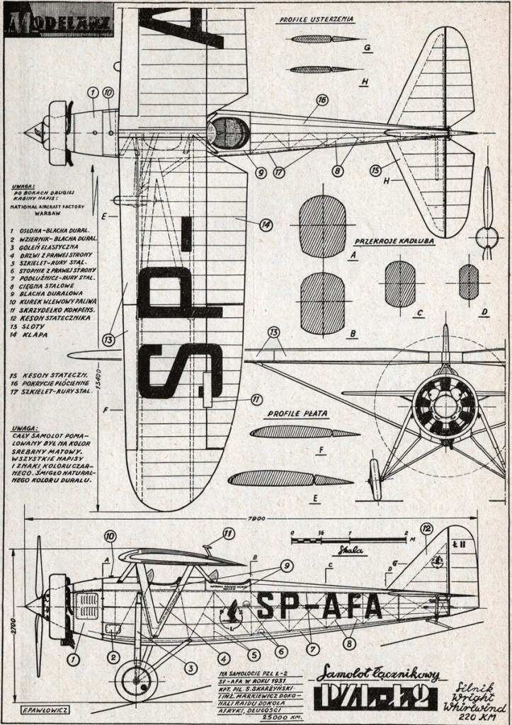
In 1927, the Polish War Ministry opened a contest for a military liaison and observation aircraft. It was meant to operate from casual airfields, used by Army land units. Jerzy Dąbrowski and Franciszek Kott from the PZL works proposed an aircraft, designated initially PZL.2. It was one of the first PZL designs, what was indicated by its low number.
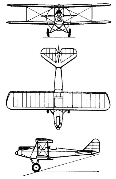
PZL Ł.2 was a high-wing braced parasol wing monoplane, conventional in layout, of all-metal construction. It had a duralumin framed, canvas covered fuselage (engine part was covered with duralumin). Crew of two was sitting in tandem in open cockpits, with twin controls. The observer had a 7.7 mm Lewis machine gun on a ring mounting. The elliptical wing was two-spar, of duralumin construction, canvas-covered, fitted with slats, flaps and flaperons. Wings could be dismounted for transport. The tail was of duralumin construction, canvas covered. It had a conventional fixed landing gear with a rear skid.
It had a 9-cylinder air-cooled Polish Skoda Works licence-built Wright Whirlwind J-5A radial engine delivering 240 hp (179 kW) at take-off and 220 hp (164 kW) nominal, driving a two-blade wooden propeller, 2.7 m diameter (in SP-AFA – metal one). 190 litre fuel tank in a fuselage (600 l in SP-AFA). Cruise fuel consumption was 45-50 l/h.
The first prototype was flown in early 1930 by Capt. Bolesław Orliński (later it received civilian registration SP-ADN) and underwent IBTL testing. In May 1930 the prototype PZL.2 was shown by Bolesław Orliński at air meeting in Brno and Bucharest, where it impressed viewers with short landing and minimal speed. After being fitted with a rear machine gun, it was shown at Paris Air Show in December 1930.
In 1930 the aircraft was tested and evaluated by the Polish Air Force. Thanks to wing mechanization (flats and slats), it had short take-off and landing. It was very advanced combination of high-lift devices in world’s aviation those days. A competing designs Lublin R-X and PWS-5t2, evaluated yet in 1929, were not satisfactory, so the Polish Air Force ordered 60 PZL.2.
The aircraft took part in the second contest for an army co-operation aircraft in July 1931. In spite of advanced high-lift devices and all-duralumin construction of the PZL.2, the air force decided to choose a simpler, cheaper and quite satisfactory Lublin R-XIII plane.
An initial order for 60 PZL.2 was finally lowered to 30, which were built between April 1930 and August 1931. The designation changed then to PZL Ł.2 (Ł for “łącznikowy”, liaison) or Ł.2a (following an early manner of PZL works to mark the aircraft purpose in designation, after a pursuit PZL P.1). Including the prototype, they carried factory numbers 55.1 – 55.31.
PZL L-2 were, in 1931-1932, 13 ET equipment with 1 GB, 43 ET with 4 GB and 63 GB ET 6, independent platoon accompanying 2 GB. One PZL L-2 was used until 1933 and by Dyon Experimental IBTL from 1932. They began to withdraw PZL L-2 units, assigning them to training. They were given to: CWOL / TSO Sztabowa ET and ET to 3 GB.
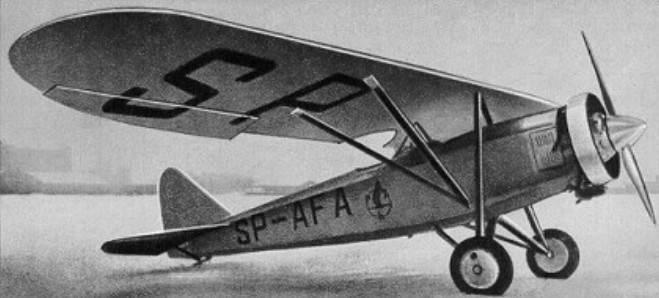
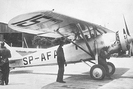
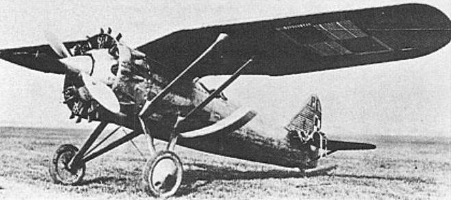
One of the Ł.2, number 55.10 was converted to a long-distance sports aircraft (civilian registration SP-AFA). It had fuel tanks 600 l and a range of over 2000 km. It was also fitted with a Townend ring.
PZL Ł.2 SP-AFA was used for several long-distance flights. Between 1 February – 5 May 1931 Cpt. Stanislaw Skarżyński with Eng. Andrzej Markiewicz flew it on a tour around Africa, on Warsaw – Belgrade – Athens – Cairo – Khartoum – Juba – Kisumu – Elisabethville – Léopoldville – Port-Gentil – Douala – Lagos – Abidjan – Bamako – Dakar – Port Etienne – Casablanca – Alicante – Bordeaux – Paris – Berlin – Warsaw 25,050 km-route (with some other stops). The aircraft was nicknamed Afrykanka then (Polish: the African female), coinciding with the aircraft registration. The tour proved a durability of the Polish-built aircraft, withstanding different weather conditions and casual airstrips, during 147 flying hours, despite the engine had to be repaired twice on the way. In 7–8 June 1931 Skarżyński flew this aircraft from Poznań in a rally to Bucharest. In July 1932 it hauled Polish gliders SG-21 and SG-28 in international competition in Rhön (piloted by Skarżyński again). It was used in the Military Camp Glider in Ustianowa and then staffs a Training Squadron 1 GB. The aircraft was written off in autumn 1935.
PZL Ł.2 SP-AFA
Due to a decrease of orders, there remained parts for several aircraft. In 1930 the PZL proposed to the Polish Navy a liaison and patrol floatplane variant of Ł.2, designated PZL.9, but it was not built. Then, the PZL proposed another patrol and fighter floatplane, basing on Ł.2 parts, PZL.15. It was a low-wing braced monoplane with thin tail boom, and utilized wings, tail and engine of Ł.2. It was not built either. Parts of Ł.2 (wings, tail, engine) were utilized in a passenger aircraft prototype PZL.16.
Serial aircraft were used by the Polish Air Force as liaison and utility aircraft from 1930, first of all in escadres Nos. 43 and 63. From 1932 they were mostly replaced with Lublin R-XIII and relegated for training, among others in Dęblin. Several were damaged in crashes. Since the aircraft started to suffer from fatigue of rivets in frame joints, they were completely written off by the end of 1935.
Produced 1930-1931, 31 were built. The Polish Air Force operated 29 aircraft and the PZL company operated two aircraft.
L-2 Engine: 1 × Skoda-Wright J-5 Whirlwind, 160 kW (220 hp) Propeller: 2-bladed wooden fixed pitch propeller Wingspan: 13.4 m (44 ft 0 in) Wing area: 25.8 m2 (278 sq ft) Airfoil: D.J.3 (modified NACA M12) Length: 7.92 m (26 ft 0 in) Height: 2.7 m (8 ft 10 in) Max take-off weight: 1282 kg / 2826 lb Empty weight: 892 kg / 1967 lb Fuel capacity: 150 l (40 US gal; 33 imp gal) Maximum speed: 183 km/h (114 mph; 99 kn) at sea level Stall speed: 63 km/h (39 mph; 34 kn) slats extended Service ceiling: 4,730 m (15,518 ft) Time to altitude: 1,000 m (3,300 ft) in 4 minutes 20 seconds 2,000 m (6,600 ft) in 10 minutes 5 seconds 3,000 m (9,800 ft) in 18 minutes 35 seconds Take-off run: 55 ma (59 sq ft) Landing run: 45 ma (48 sq ft) Range: 660 km Armament: 1x 7.7 mm (0.303 in) Lewis machine gun Crew: 2
PZL L-2 rally Engine: 1 × Skoda-Wright J-5 Whirlwind, 160 kW (220 hp) Wingspan: 13.4 m Length: 7.92 m Height: 2.7 m Wing area: 25.8 m2. Empty weight: 970 kg MTOW: 1730 kg / 3,814 lb Fuel capacity: 630 lt (170 US gal; 140 imp gal) Max speed 200 km / h Cruise: 185 km / h Stall: 77 km / h Range: 2000 km
Evolved from the P.1 by Zygmunt Pulawski and developed in parallel with the P.7, the P.6 was powered by a low-altitude Gnome-Rhone Jupiter 9Ac (VI.FH) nine-cylinder radial rated at 450hp. The principal change from the P.1, apart from the power plant, was to be found in the fuselage structure and fuel disposition, the rear fuselage being a semi-monocoque and the wing tanks of the earlier fighter giving place to a jettisonable fuselage tank. Armament remained two Vickers “E” machine guns (rebored to 7.92mm calibre). The first of two P.6 prototypes was flown in August 1930, and, in the following year, participated in the National Air Races at Cleveland, Ohio. The second prototype, the P.6/II, differed primarily in having a Townend ring cowling in place of the narrow ring of the P.6/I. The Lotnictwo Wojskowe elected to order the contemporary P.7 for series production and no further development of the P.6 was undertaken.
Max take-off weight: 1355 kg / 3 lb Empty weight: 908 kg / 2002 lb Wingspan: 10.30 m / 34 ft 10 in Length: 7.16 m / 24 ft 6 in Height: 2.75 m / 9 ft 0 in Wing area: 17.30 sq.m / 186.22 sq ft Max. speed: 292 km/h / 181 mph Range: 600 km / 373 miles
The first fighter of indigenous Polish design, the P.1 produced by the Paristwowe Zaklady Lotnicze (P.Z.L.), or National Aviation Establishment, embodied several technical innovations. Designed by Zygmunt Pulawski, the P.1 was of all-metal construction, its most novel feature being the “gulling” into the fuselage of the centre section of the high wing, thus eliminating the normal cabane. This both reduced drag and improved the forward view for the pilot. Powered by a 12-cylinder water-cooled Hispano-Suiza 12 Lb Vee-type engine affording 630hp for take-off, the first prototype, the P.1/I, was flown on 25 September 1929. Armament comprised two 7.7mm Vickers machine guns. The second prototype, the P.1/II, featured a repositioned radiator bath and redesigned vertical tail surfaces, and joined the test programme in March 1930. Further development was discontinued in favour of radial-engined variants, as the Polish air arm, the Lotnictwo Wojskowe, was biased against liquid-cooled engines.
Engine: Hispano-Suiza 12 Lb, 630hp Max take-off weight: 1580 kg / 3483 lb Empty weight: 1118 kg / 2465 lb Wingspan: 10.85 m / 36 ft 7 in Length: 6.98 m / 23 ft 11 in Height: 2.96 m / 10 ft 9 in Wing area: 19.50 sq.m / 209.90 sq ft Max. speed: 302 km/h / 188 mph Range: 600 km / 373 miles Armament: two 7.7mm Vickers machine guns
Founded January 1928 as Poland’s National Aircraft Establishment, built the P.1 single-seat fighter monoplane with Hispano-Suiza engine in 1929-1930, and subsequently the P.11 single-seat fighter and P.19 cabin monoplane. The PZL Los medium bomber of 1937 was followed by the Wilk twin-engined fighter, Sum light bomber and Mewa reconnaissance monoplane by the beginning of Second World War. Factories at Warsaw- Okecie (original) and Mielec, latter used by occupying Germans as forced-labour Heinkel factory 1940-44.
Under political reorganization in 1956, the Polish aircraft industry was revived with production of Soviet aircraft and some indigenous types. In foreign markets most Polish aircraft subsequently appeared under the PZL title, such as the PZL-101 Gawron and PZL-104 Wilga utility aircraft of 1960 and 1962 respectively, the first being a development of the Yak-12. The Gawron was used extensively as an agricultural aircraft, along with the PZL-built An-2 biplane, but later purpose-built dusters and sprayers were built. PZL types are produced under three separate organizations: PZL “Warszawa-Okecie” SA, WSK “PZL-Mielec” SA, and PZL-Swidnik SA.
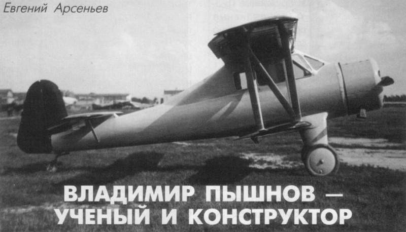
In addition to scientific-investigative work, VS Pyshnov once again decided to try its hand at construction activity. In 1935 he developed the project of a light aircraft that received the name VVA-1 (Military Aeronautical Academy – 1).
The VVA-1 was designed to meet the requirements of a light aircraft contest promoted by Osoaviajim in 1934. During the design, Pyshnov placed special emphasis on obtaining comfort for the passengers, the exterior finish of the model and the decrease in landing speed, obtaining a multi-purpose aircraft intended for use as a trainer, tourism aircraft, light transport and liaison aircraft.
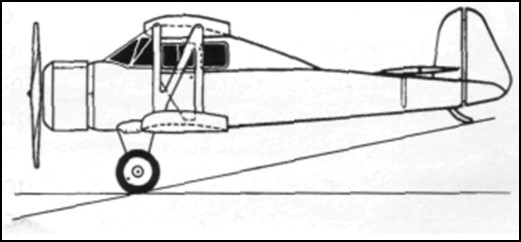
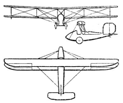
Structurally, the VVA-1 was designed as a sersquiplane with wings of equal width and a closed cabin made almost entirely of wood, using pine for the structure and plywood for the fuselage covering. The cowl was covered with steel plates and the wing and control surfaces were covered with fabric.
The fuselage featured a monocoque structure with a circular cross section. The construction had 17 frames and 4 stringers of variable section (30 x0 30 mm in the engine area and 20 x 20 mm in the tail area, as well as 10 stringers of 10 x 15 mm. The fuselage had a plywood covering of 3 mm in the front and tail area and 2 mm in the central area. To ensure greater rigidity, the fuselage had practically no perforations.
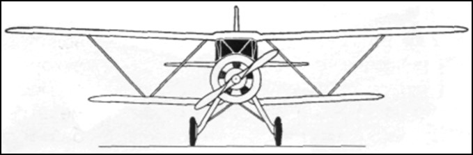
The wing box had a wooden structure with rigid “W” braces. The wing was rectangular in shape with rounded wingtips and consisted of two box-frame spars with three layers of pine and 3mm plywood walls. The leading edge was produced independently, being mounted on the wing once the fabric covering was finished. The wing struts were also made of pine with an aerodynamic profile and their junction with the wing was faired to reduce drag. Ailerons were included only on the upper wing, which also featured flaps that could be operated up to 30º angles. Norton-Shrenk type flaps capable of tilting at 45º were included in the lower wing.
The wing profile of the midline responded to that of the TsAGI-RP profile with decreased curvature, but the thickness responded to the NACA profile with a relative thickness of 10.5%.
The upper wing consoles were fixed to the centerplane located above the closed cockpit. The lower wing was fixed directly to the fuselage and to reduce interference in the joint area it presented an inverted gull configuration. Another notable feature was the possibility of collecting the wings backwards, pivoting on the rear spar. In this way the width of the aircraft decreased from 11 to 3.4 meters.
The tail section featured an unconventional design. The horizontal stabilizer was located quite forward on the tail cone and on top of the fuselage. The empennage was cantilever and was fixed to the last frames of the fuselage. This configuration was specially selected in order to improve the work of the tail unit in the event of a spin entry, by eliminating the influence of one surface on the other.
The stabilizer had a main spar located over 27% of the wing chord and a secondary spar located on the elevator attachment edge. The uprights that were attached to the structure on both sides of the fuselage were attached to the main spar. The front of the stabilizer was lined with plywood. The rest was received with tissue. The angle of incidence of the stabilizer could be adjusted on the ground. The structure of the depth rudder was made of wood with a textile covering.
The VVA-1 featured duplicate sticks, but the second stick could be removed. The double control pedals were linked to each other by means of a tube. Elevator control was mixed. In the lower part of the cabin it was rigid, but further on it was still on cables. Control of the ailerons was rigid, while that of the elevator was cable. The aileron actuators could be easily disengaged to allow retraction of the wings.
The main landers featured aerodynamically faired legs and rubber shock absorbers with 700 x 100 mm unbraked wheels. The tail unit also featured spring damping and was free to rotate. The rear landing gear was calculated to install a skid or a wheel, interchangeably.
The powerplant selected was the 110-hp air-cooled M-11 radial engine. The engine was fixed to the fuselage by four points with the help of a frame made of “M” steel. The engine was covered by two hoods, one inside and one outside. To ensure engine cooling, the outer hood had adjustable holes located in front of the cylinders. The flight could be carried out only with the inner hood. For the VVA-1 a special fixed-pitch wooden propeller was designed.
The engine’s power system consisted of two fuel tanks. The main tank had a capacity of 100 liters and was located in the center of the plane. About the cabin. The second tank was located in the fuselage, between the engine and the cockpit instrument panel. The motor feeding could be done from each tank independently or from both. In the upper tank, a floating system was located that indicated the remaining fuel. The lubrication system was taken from the Polikarpov Po-2.
The cabin of the VVA-1 was closed and in the normal version it accommodated three people. The plioto was located in the front left position and behind it was a divan for two passengers. On the pilot’s right side a fourth seat could be installed to use the aircraft’s dual control system. To access the cabin, two doors located on the sides, on the lower wing, were used.
The instrument panel included a speedometer, turn signal and artificial horizon, barometer, clock, compass, rev counter, engine temperature and oil pressure indicator. Lighting was installed for the panel and for the cockpit.
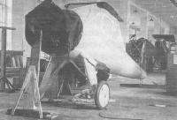
The VVA-1 was built in the workshops of the Military Aeronautical Academy. In the summer of 1935 the plane was ready for testing. In relation to the calculations of the project, the plane turned out to be much heavier. Calculated for an empty weight of 580 – 600 kg the prototype weighed 845 kg, with a takeoff weight of 1146 kg.
In August 1935 the aircraft was handed over to the NII VVS for development of state tests. NS Kulikov was designated as the main engineer and the test pilot was KA Kaliliets. The test program established 14 flights to establish the benefits and the main operating data. The tests took place between August and September and were carried out without the outer bonnet and without the planned propeller. When testing this propeller, both on the ground and in flight, a large vibration appeared throughout the airframe. For this reason this propeller was replaced by that of a Po-2. With this propeller the vibration did not completely disappear, but it decreased considerably. In the tests, a speed of 156 km/h at sea level was obtained with a takeoff weight of 1146 kg and 145 km/h at 2000 meters of altitude. The height of 1000 meters hated to be reached in 9.83 min and the 2000 m in 26.19 minutes. The ceiling of 2920 meters could be reached in 76.9 minutes. Landing speed with flaps extended was 75 – 90 km/h.
The plane behaved well on takeoff, but it was heavy and the tail lifted with difficulty. It lacked a tendency to take off from the ground, so the pilot felt the need to “force” it. Using the flaps did not improve takeoff, shortening it only by about 60 meters. Another problem was the tendency of the plane to drift during the takeoff run, which forced the pilot to not neglect control of the controls to correct the problem.
The rate of climb was considered very low. To rise to 30 meters, the plane needed to travel 500 or 600 meters, which, together with a run of about 240-300 meters for takeoff, made it impossible to use it at aerodromes with short runways or with obstructions near the end of the runway.
Visibility from the cabin forward and to the left was considered good, to the right and to the sides, bad and to the rear was not possible. Long flights were exhausting for the crew, especially due to the poor distribution of the steering components and the uncomfortable position of the seats.
In calm skies the plane behaved quite well, but in turbulence its behavior was capricious. Maintaining the instrument course was quite difficult as the compass was far away on the panel and it was difficult for the pilot to follow it.
Unlike takeoff, landing was very easy. The aircraft landed with good stability. Without the flaps the landing run increased to about 180 meters.
In the report it was stated that due to the discomfort of the seat, the poor distribution of the instruments and equipment, the excessive sensitivity of the rudder, the low ascent speed and the lousy design of the control organs, the VVA-1 demanded too much attention of the pilot. As positive values of highlighted the excellent stability and ease of handling.
The military pilots pointed out that the performance obtained was too low and the aircraft too heavy, which led to a considerable decrease in the calculated payload capacity. The takeoff and landing runs were too long and the takeoff technique too complex, which confined it to operation on large aerodromes with good runways. The use of the flaps was very ineffective and the landing speed remained high. The poor work of the flap control organs, the uncomfortable position of the control stick, the poor vision through the cockpit glass in bad weather and the absence of rearward and upward visibility were also noted.
In the conclusions of the report it was written: ” due to its performance and operating data, the VVA-1 aircraft is of no interest… “
It was considered useless to make modifications to the plane because it was considered that the main drawbacks of the plane came from its aerodynamic design, but the possibility of building a new example that took advantage of the positive elements of the design was left open, while at the same time managing to eliminate the indicated deficiencies and cover the requested technical specifications. Budget cuts at the Military Aeronautical Academy prevented the construction of this new model.
Given the impossibility of building a new prototype, the first VVA-1 was modified in order to reduce some of the signals made during the tests. Among the changes made, work was done to improve the control of the rudder by reducing its surface and installing a compensation system to reduce sensitivity. The landing gear was modified, a more powerful powerplant was installed and the hood was modified. Added a new fuel tank. The fairings at the junctions between the W-pillars and the wing were removed. These changes increased the empty weight of the plane to 1,160 kg, so military use was ruled out, defining the use of the model as a sports and tourism plane.
In 1937 the modernized VVA-1 was delivered to the NII VVS and several familiarization flights were carried out on it. These flights demonstrated stability problems in the vertical axis. The builder was asked to increase the surface of the empennage and replace the wheel train with one made of skis. Lack of funds for development programs at the Military Aeronautical Academy prevented further modifications.
VVA-1 Powerplant: One 110 hp M-11 Wingspan: 11.0 m Wing area: 21.28 m² Length: 7.8m Height: 2.85m Empty weight: 845 kg Maximum takeoff weight: 1146 kg Fuel capacity: 110 kg Payload: 301 kg or 2 passengers Maximum speed: 156 km/h Minimum flight speed: 100 km/h Landing speed: 75-90 km/h Cruising speed: 135 km/h ROC: 2.05 m/s Ceiling: 2920 m Take-off run with flaps: 220-260 m Landing roll: 180-200 m Accommodation: 1 – 2
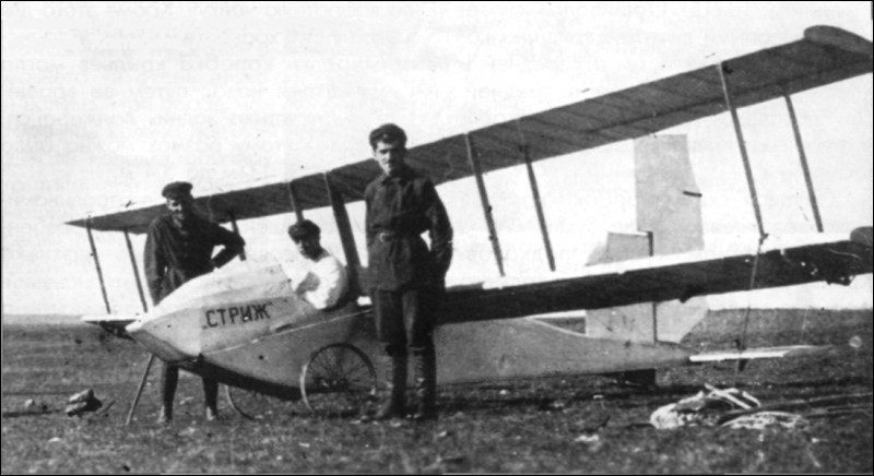
Vladimir Pyshnov at Koktebel during the 1923 competitions alongside the AVF-2 “Strizh” with the modified tail rudder.
In 1923 the Academy of the Air Fleet and the Military Academy of the RKKA leadership allowed students to build gliders and light aircraft using the academy workshops.
Between 1 and 18 of November of 1923 took place in Uzun-Sirt mountains in Crimea First National Competitions Gliding. In these competitions 10 gliders were presented. Among them were three Air Fleet Academy student gliders named AVF-1 Arap , AVF-2 Strizh and AVF-3 Mastyazhart and built by students MK Tijonrarov, VS Pyshnov and SV Ilyushin respectively. The technical commission, chaired by Professor VP Vetchinkin, after reviewing them, allowed the flight of 9 of them.
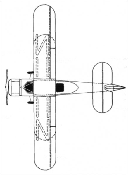
Pyshnovs’ AVF-2 Striz (Russian: Пышнов АВФ-2 «Стриж») glider had a biplane structure with long wings. The fuselage was constructed entirely of wood, with cable ties and featured a rectangular cross-section with a curved top. The fuselage structure ended in a horizontal rib towards the tail. The covering was fabric.
The wing trunk was located above the fuselage. The upper flange had an offset of 0.3 meters and the distance between both planes was 0.9 meters, being joined by means of parallel uprights and braced by cables. The wing construction was also made of wood, with textile covering and corresponded to the Prandtl-387 profile. Roll control was carried out by ailerons located in both planes.
The monoplane tail unit featured a large elevator attached to the rear frame of the fuselage and a large area empennage to which the rudder attached.
The landing gear was of the conventional type with two large spoke bicycle wheels whose axle ran from side to side through the fuselage and was attached to rubber shock absorbers. In the tail it had a fixed skate to the structure.
The pilot was located in a cockpit in front of the wing leading edge.
The Pyshnov glider was the second model designed and produced at the Air Fleet Academy (AVF), for which it received the official designation AVF-2 and the nickname “Strizh.” The Strizh was built in the AVF workshops and assembled at the “Aviarabotnik” factory. Unfortunately by the time the competitions started in November 1923 the AVF-2 had not been finished and was sent to the competitions in that state. All the metallic fixings were already installed in the camp of the participants in the competition.
This situation played a negative role in the fate of the glider. The Strizh was not only incomplete, it had not been tested, so construction defects had not been corrected. During the first tests on November 15 the Strizh on several occasions rotated on its axis before reaching takeoff. To correct this difficulty the builders increased the rudder area considerably but after this the glider refused to rise.
As a consolation, in this competition they also failed to launch their gliders SN Lyushin with their “Maori” and VI Cheranovski with their BICh-1 “Parabola”. Despite the difficulties the 17 of February of 1924, during the conclusions of the first competitions of gliding, the builder VS Pyshnov to the present like other builders, received a special award for its creation.
AVF-2 “Strizh” Wingspan: 10.2 m Wing area: 12.5 m² Length: 4.7 m Height: 1.8 m Elevator area: 1.6 m² Keel rudder area: 0.6 m² Rudder surface area: 0.5 m² Ailerons surface: 2.2 m² Empty weight: 60 kg Wing loading: 10 kg / m²