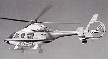
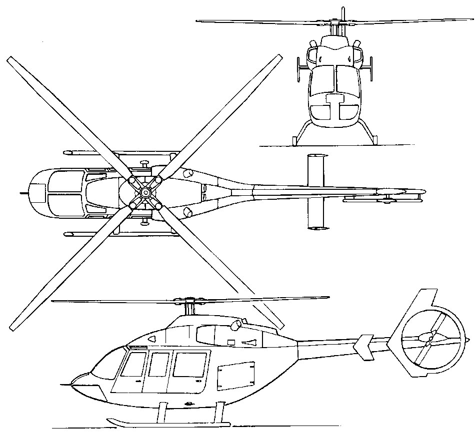
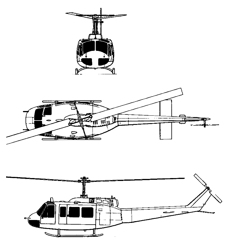
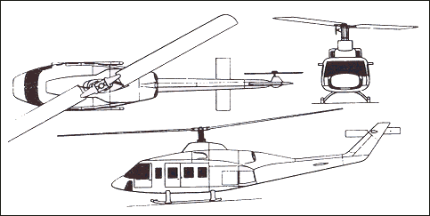
In February 1983, Bell announced the both commercial and military, single and twin-engined, Model 400 TwinRanger. This seven-seat aircraft was in the 1800-2700kg gross weight class. The Model 400 was powered by two 443shp Allison 250-C20R turboshaft engines, had a four-blade soft-in-plane main rotor, an advanced technology transmission and drive system with ‘run-dry’ capability. The aircraft entered development in 1983 with wind-tunnel testing with a one-quarter scale model and flight testing of the dynamic components on a specially modified Model 206LM LongRanger (c/n 45003, N206N) which served as test-bed and flew in March 1983. This aircraft had the four-bladed OH-58D AHIP rotor, a strengthened tail boom, a ring guard tail rotor and a deepened fuselage to increase fuel capacity. The first prototype Model 400 (c/n 48001, N3185K) flew on 30 June, 1984, powered by Allison engines. Three pre-production Model 400 TwinRangers (c/n 48002/ 48004) were built, the first of which (N3185L) flew for the first time on 4 July, 1985, the second (N3185U) in May and the third (N400BH) in June 1985. The first aircraft was later used as a ground test vehicle. It was expected that the Canadian factory, at Mirabel, Montreal, would undertake production of the Model 400 and develop the Model 400A, a variant of the Model 400 powered by a single 1000shp Pratt & Whitney Canada PW209T turboshaft engine, and employing major composites components. The programme was suspended indefinitely pending a market situation that would support an annual sales rate of about 120 aircraft. The four existing aircraft have been cancelled from the register and put in storage by Bell Helicopter Textron Canada, at Mirabel.
Model 400 Rotor diameter: 11.30m Overall length: 13.39m Length of fuselage: 11.02m Height overall: 3.56m Maximum take-off weight: 2495kg Empty weight: 1427kg Maximum speed: 278km/h Maximum cruising speed at 1525m: 244km/h Initial rate of climb: 464m/min Service ceiling: 6100m Hover ceiling outside ground effect: 3110m Hover ceiling in ground effect: 4360m Maximum range: 834km
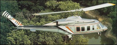
At the 1989 NBAA Convention, Bell announced its intention to develop an improved variant of its Bell 222. Powered by two 700shp Allison 250-C30-G2 turbines driving an advanced design two-blade rotor, the Model 230 could carry up to ten people in a 3.8cu.m passenger compartment. Internal fuel capacity had been increased to 930 litres with a maximum of 1359 litres with optional fuel tanks. A fixed skid undercarriage is also available and, from the 51st production aircraft, Bell will offer a variant powered by Lycoming LTS101-750 turbo-shafts. This helicopter is to be built at the company’s facility in Canada.
Two prototypes were converted from Bell 222s at the Mirabel factory near Montreal and the first of these (registered C-GEXP) accomplished its maiden flight on 12 August, 1991. The type received Transport Canada type approval on 12 March 1992 and the production aircraft (C-GAHJ) first flew on 23 May 1992. Deliveries began on 16 November 1992. A total of 37 were delivered by January 1998. The second prototype (C-GBLL) flew on 3 October 1991. An initial order for twenty was placed by Bell’s Japanese representative Mitsui & Co, in Tokyo, with first deliveries due in August 1992.
A Military demonstrator (N230CN) was leased for six months by Chilean Navy 1993-94, equipped for shipboard evaluation with Indal ASIST deck recovery system, auxiliary fuel tanks, Breeze Eastern BL 1600 rescue hoist, AlliedSignal RDR 1500B radar, Teledyne AN/APX-101 transponder, AlliedSignal KHF-950 SSB transceiver, Magnavox AN/ARC-164 UHF, Rockwell AN/ARC-186 VHF, Spectrolab SX-5 Starburst searchlight, Agema thermal imager in Heli-Dyne turret, Honeywell EDZ-705 EFIS with SPZ-7000 AFCS, Trimble TNL 7880 GPS/Omega and Flight Visions FV2000 HUD.
The first 50 aircraft were powered by two Allison 250-C30G2 turboshafts, each rated at 522kW for 5 minutes for T-O, 464kW maximum continuous, 581kW OEI for 2.5 minutes and 553kW OEI for 30 minutes. Main transmission rated at 690kW for T-O, 652.5kW maximum continuous and 548kW for single-engined operation. Usable fuel capacity 935 litres in skid gear version, 710 litres in wheeled version. Optional 182 litres of auxiliary fuel for both versions. Equipped with a two-blade main rotor with stainless steel spars and leading-edges, Nomex honeycomb trailing-edge with glass fibre skin, and glass fibre safety straps; tail rotor blades stainless steel. Aluminium alloy fuselage with integral tailboom and some honeycomb panels. The landing gear is a tubular skid type on Utility version. Executive version to have hydraulically retractable tricycle gear, single mainwheels retracting forward into sponsons; forward-retracting nosewheel fully castoring and self-centring; hydraulic disc brakes on main units. Controls are fully powered hydraulic, with elastomeric pitch change and flapping bearings; fixed tailplane with leading-edge slats and endplate fins; strakes under sponsons; single-pilot IFR system without autostabilisation. Standard layout has forward-facing seats for nine persons (2-2-2-3) including pilot(s). Options include eight-seat executive (rear six in club layout), six-seat executive (rear four in club layout with console between each pair), or 10-seat utility (2-2-3-3, all forward-facing). Customised Emergency Medical Service (EMS) versions also available, configured for pilot-only operation plus one or two pivotable stretchers and four or three medical attendants/sitting casualties respectively. Two forward-opening doors each side. Entire interior ram air ventilated and soundproofed. Dual controls optional. The main and tail rotors substantially same as Bell 222, former having Wortmann 090 blade section with 8 per cent thickness/chord ratio and swept tips. Independent (hydraulic) rotor brake. Short span sponson each side of fuselage houses mainwheel units and fuel tanks, and serves as work platform.
Bell 430 Preliminary design began in 1991 for a four-blade rotor, higher-powered and stretched variant of Bell 230, The programme was launched in February 1992 and two prototypes were modified from Bell 230 airframes: first prototype (C-GBLL; wheel-equipped) flown 25 October 1994; second prototype (C-GEXP; skid-equipped, with complete avionics suite) flown 19 December 1994. The first flight of a production 430 (C-GRND) was in 1995 and deliveries began on 25 June 1996 after Canadian type approval on 23 February. The second production aircraft, N4300 circumnavigated the world in a record time of 17 days 6 hours 14 minutes, landing back at Fairoaks, UK, on 3 September 1996. Neiman Marcus Special Edition was introduced in 2001 for Neiman Marcus store’s 75th Christmas catalogue, featuring three-colour custom metallic exterior paint scheme with NM signature. Italian leather and rosewood interior, sculpted carpets with NM logo, passenger refreshment centre, Blaupunkt AM/FM/CD entertainment centre. JetMap cabin information system with moving map displays on two ceiling-mounied monitors. Motorola cellphone and two computer ports. The first delivery, on 25 June 1996, was the sixth production aircraft (N6282X) handed over to IPTN (now Dirgantara) of Indonesia in eight-seat executive configuration. Thirteen were delivered in 1996; followed by eight, 15 and 18 in 1997-99, 11 in 2000, 14 in 2001 and seven in 2002.
430
Optimised for high cruising speed with (retractable) wheel landing gear, although traditional skids optional; inclined towards executive transport market. Bell 230 fuselage lengthened by 0.46m plug; Bell 680 all-composites four-blade bearingless, hingeless main rotor; approximately 10% power increase over Bell 230; uprated transmission; and optional EFIS. Short-span sponson each side of fuselage houses mainwheel units and fuel tanks, and serves as work platform. Fully powered hydraulic, with elastomeric pitch change and flapping bearings; fixed tailplane with leading-edge slats and endplate fins; strakes under sponsons; single-pilot IFR system without auto-stabilisation. Semi-monocoque fuselage of light alloy, with limited use of light alloy honeycomb panels. Fail-safe structure in critical areas. One-piece nosecone tilts forward and down for access to avionics and equipment bay. Short span cantilever sponson set low on each side of fuselage, serving as main landing gear housings, fuel tanks and work platforms. Section NACA 0035. Dihedral 3deg 12min. Incidence 5deg. Sweepback at quarter-chord 3deg 30min. Fixed vertical fin in sweptback upper and lower sections. Tailplane, with slotted leading-edge and endplate fins, mounted midway along rear fuselage. Small skid below ventral fin for protection in tail-down landing. Four-blade main rotor with stainless steel spars and leading-edges. Nomex honeycomb trailing-edge with glass fibre skin, and glass fibre safety straps; tail rotor blades stainless steel. Rotors shaft-driven through gearbox with rwo spiral bevel reductions and one planetary reduction. Main blade and hub life, 10.000 hours. Tubular skid type on Utility version. Executive version has hydraulically retractable tricycle gear, single mainwheels retracting forward into sponsons; forward-retracting nosewheel fully castoring and self-centring; hydraulic disc brakes on main units. Mainwheel tyre size 18×5.5, nosewheel 5.00-5. Emergency floats optional. Two Rolls-Royce 250-C40B turboshafts, each rated at 603kW for T-O and 518kW maximum continuous. OEI ratings 701kW for 30 seconds, 656kW for 2 minutes, 623kW for 30 minutes and 602kW continuous. Chandler Evans FADEC. Transmission rating 779kW for 5 minutes for T-O, 737kW maximum continuous. Power train TBO, 5,000 hours. Usable fuel capacity 935 litres in skid version, 710 litres in wheeled version; provision in both versions for 182 litre auxiliary tank. Fuel system is rupture resistant, with self-sealing breakaway fittings. Standard layout has forward-facing seats for nine persons (two-two-two-three) including pilot. Options include 10-seat layout (two-two-three-three); eight-scat executive (rear six in club layout), six-seat executive (rear four in club layout with console between each pair); and five- and four-seat executive with one or two refreshment cabinets; seat pitches vary between 86cm and 91cm. Pilots on crashworthy (energy attenuating) seats, which are optional for passengers. Customised emergency medical service (EMS) versions also available, configured for pilot-only operation plus one or two pivotable stretchers and four or three medical attendants/sitting casualties respectively. Two forward-opening doors each side; EMS version has optional stretcher door between forward and rear doors on port side. Entire interior ram air ventilated and soundproofed. Dual controls optional. Standard equipment includes rotor and cargo tiedowns, ground handling wheels for skid version, retractable 450W search/landing light. Options include dual controls, auxiliary fuel tankage, force/feel trim system, more comprehensive nav/com avionics, 272kg capacity rescue hoist, 1587kg capacity cargo hook, emergency flotation gear, heated windscreen, particle separator and snow baffles. The programme cost US$18 million, 35% financed by Canadian Defence Industry Productivity Program (DIPP) and repayable as royalty on each sale.
Bell 230 Engine: 2 x Allison 250-C30G/2, 720 shp each, dual max: 690 kW. Instant pwr: 520 kW. Rotor dia: 13.8 m. Empty wt: 2270 kg. MTOW: 3813 kg. Payload: 1472 kg. Useful load: 1270 kg. Max speed: 140 kts. Vne: 150 kts. Max cruise: 135 kts. Max range: 705 km. HIGE (@MAUW): 12,400 ft. HOGE (@MAUW): 7300 ft. Service ceiling: 14,100 ft. Opt fuel cap: 1359 lt Crew: 1/2. Seats: 8/10. Rescue hoist capacity: 136kg Cargo hook capacity: 1,270kg
Bell 430 Engine: Allison 250-C40. Instant pwr: 582 kW. Rotor dia: 13.8 m. MTOW: 5443 kg. Max cruise: 135 kts. Vne: 150 kts. Max range: 705 km. Seats: 8/10.
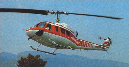
At the beginning of the 1970s a more powerful variant of the Model 205 (UH-1H) had been studied in which a 1,900shp Lycoming T53-L-702 turboshaft had replaced the standard 1,400shp T-53-L13 unit. The version, designated Model 214 HueyPlus, also retained the main rotor and tail rotor drive systems and the larger two-blade rotor of the Model 309 KingCobra (composite elasto¬meric), these offering better high speed and weight performance as well as reduced noise. The airframe was also strengthened including the pylon structure and fuselage. The Model 214 prototype flew for the first time at Arlington in October 1970 powered by a 2185kW Avco Lycoming LTC4B-8D turboshaft engine. Development of the HueyPlus progressed steadily until 1972 when Iranian Army Aviation approached Bell for the design of a UH-1 derivative which could be operated in hot and high conditions. Several hundreds of this new type of helicopter would be delivered together with some two hundred AH-1J Cobras. A $500 million contract for 293 machines was signed on 22 December, 1972, by the US Army, acting on Iran’s behalf. During the first phase of this programme, Bell built three additional prototypes of the Model 214. These were powered by 2,050shp Avco Lycoming T55-L-7C turbo-shafts, and in August 1972, one of them was shipped to Iran for evaluation. The tests were considered successful and Bell moved on to the Model 214A which was the production model. On this variant, power was increased further by the installation of a 2,930shp Avco Lycoming LTC4B-8D turboshaft which permitted operation at a greater gross weight. Three prototypes of the Model 214A were prepared by Bell (c/n 27001/27003), the first (N214J) making its maiden flight on 13 March, 1974. The second prototype flew in April 1974 and the third in May. Flight testing and certification were resumed in the following year. The first production 16-seat Model 214A (c/n 27004) was taken in charge by the Iran Imperial Army Aviation (IIAA) on 26 April, 1975, which gave them the name Isfahan. Three days later, on 29 April, this aircraft with Maj-Gen Manouchehr Khosrowdad, commander of the IIAA, and Clem A Bailey, Bell’s assistant chief production test pilot, at the controls, established five new world records in the FAI Class E-1e. The helicopter reached a maximum altitude of 9070m and sustained a horizontal altitude of 9010m for 30 seconds. It also climbed to 3000m in 1min 58sec; to 6000m in 5min 13.2sec and to 9000m in 15min 05sec. Subsequently, 39 generally similar aircraft, but with specific equipment for SAR operations, were delivered to the Iranian Air Force under the designation Bell Model 214C. The second batch was ordered in February 1976, and delivered between January 1977 and March 1978. A third batch of six Model 214As was ordered in March 1977 and this order was completed by the autumn of 1978. The last Model 214A of the first batch was completed on 19 December, 1975. Known as Model 214B BigLifter, this helicopter received FAA type certification on 27 January, 1976, but saw limited success and no more than seventy were produced. The Model 214B was externally similar to the Model 214A with the exception of an additional window in the side sliding door. Other differences included a fire-fighting system and new avionics. The Model 214B-1 variant was certificated under a different weight specification. In its Isfahan plant, Iran intended to produce a larger and more powerful variant of the Model 214A capable of carrying up to 16 people and incorporating a stretched and widened fuselage. A Model 214A was modified by Bell with the installation of two 2,250shp General Electric T700/T1C turbo-shafts and tested in Iran in February 1977. The definitive Model, known as Model 214ST (ST stood for ‘Stretched Twin’, but this was later modified to ‘Super Transport’), had its fuselage stretched by 2.44m. Bell assembled three prototypes (two for commercial certification and one of the military variant, c/n 18401/ 18403). Bell initiated the production of a first batch of 100 Model 214ST in November 1979. The first prototype (c/n 18401, N214BH) flew on 21 July, 1979. The production examples were powered by 2,930shp Avco Lycoming LTC4B-8Ds driving a large five-blade rotor with Noda-Matic head. In 1982, the Model 214ST received FAA and CAA type certification for VFR and IFR operations. The 214ST is fully IFR certified and has a computer-controlled fly-by-wire automatic elevator trim system, plus a stability and augmentation control system and main rotor blade in-flight tracking system. A version with wheel undercarriage was certificated in March 1983. Designed for long-range offshore oil operations with cruise speeds of 140 knots, the 214ST operates to 650 kilometres range with 45 minutes reserve. Bell’s Super Transport can lift over three tons even on hot days at high altitudes. The Super Transport General Electric CT7-2A engine modules are designed for mechanical simplicity, requiring only 12 basic tools for line maintenance and module replacement. Options such as life rafts, pop-out floats, internal hoist or two 310 litre auxiliary tanks can be added.
Bell 214ST
Two versions were available, and the standard Model 214B was intended for a variety of purposes. They included operation as a 14-passenger transport with a crew of two; as a cargo lifter, with an external cargo hook certificated to carry a maximum load of 3629kg; in an agricultural role, carrying a very similar chemical load; or as a firefighter able to drop a total 2725 litres of fire retardant, carried in cabin and under-fuselage tanks. The alternative Model 214B-1 was certificated to different standards that allowed for operation at a lower gross weight with an internal load. The Model 214B was available to commercial operators from the receipt of certification on 27 January 1976 until production ceased in 1981.
The 214B BigLifter is derived essentially from the 204 and 205, and was specifically designed to better the lift capacity of any contemporary civil helicopter of the same power. The key to the type’s considerable lifting ability is the use of a 2930shp Lycoming T5508D turboshaft (the civil version of the T55-LTC4B-8D turboshaft powering the 214A and its search-and-rescue derivative, the 214C), flat-rated to 2250shp maximum output. The rotor and transmission are identical with those of the 214A, the transmission being capable of accepting up to 2050shp at take-off and 1850shp for continuous running. The rotor system is of an advanced type, the blades having swept tips and the hub featuring elastomeric bearings on the flapping axis. The twin-blade tail rotor has a hub which needs no lubrication. Other advanced features of the type are the use of an automatic flight-control system, with the capability of altitude maintenance and augmented stability; dual hydraulic systems; a nodalized suspension (Bell’s patented ‘Noda- Matic’ concept of 1972, by which the fuselage is suspended from points of no relative motion in the engine mounting) to reduce fuselage vibration by about 80%; and an engine decking that is also used as a maintenance platform for the engine, transmission and rotor hub. The 214B BigLifter carries to an extreme the Bell design philosophy of a twin-blade wide-chord main rotor, each of the blades having a chord of no less than 88.9cm. The transmission and rotor-drive systems are well proved by earlier use in the 214A, after development in the experimental KingCobra gunship helicopter. Although it is intended mainly as a weight-lifter, the 214B can carry up to 14 passengers in addition to its crew of two. As a weight-lifter, however, the 214B can carry up to 1814kg internally, or up to 3175kg externally on its cargo hook, which is cleared for flight with loads weighing up to 3629kg. This weight-lifting capacity is also useful in the agricultural role, in which up to 3629kg of chemicals or 3023 litres of liquid can be uplifted. The considerable liquid-carrying capability of the 214B is also useful for fire-fighting. The Model 214B-1 is intended for different certification standards, and is thus limited in the internal load-carrying role to a maximum take-off weight of 5670kg. Production began in 1981, deliveries started in 1982 and by the beginning of 1984, some twenty machines were in service and seventy-eight had been delivered by early 1988. Among the first operators were British Caledonian Helicopters (c/n 28109/28110; G-BKFN and G-BKFP) which operated offshore in the North Sea and People’s Republic of China. By 1992 some two hundred Model 214STs have been sold. The bulk of the Model 214ST production has found its way on to the civil market and only a few have been delivered to military customers: Brunei (one), Peru (eleven), Thailand (nine) and Venezuela (four) and Sultan of Oman’s Air Force which operated eight Model 214B/STs from Salalah during the war against Iraq in January/February 1991. The Bell 214ST features: ROTOR SYSTEM: Two-blade advanced technology main rotor. Each blade has a unidirectionally laid glass fibre spar, with a 45degree wound torque casing of glass fibre cloth. The trailing-edge is also of unidirectional glass fibre, and the space between spar and trailing-edge is filled by a Nomex honeycomb core. The entire blade is then bonded together by glass fibre wrapping, with the leading-edge protected by a titanium abrasion strip and the tip by a replaceable stainless steel cap. Two-blade tail rotor; interchangeable blades, each with a stainless steel leading-edge spar and covering, aluminium honeycomb core and glass fibre trailing-edge strip. Main rotor head incorporates elastomeric bearings. Second-generation Noda-Matic nodal suspension system. Nodal beam requires no lubrication. Main rotor brake standard. ROTOR DRIVE: Main transmission has a maximum rating of 1,752kW, maximum continuous rating of 1,454kW, and single-engine rating of 1,286kW. Combining, intermediate and tail rotor gearboxes, each with 1 hour run-dry capability. FUSELAGE: Conventional all-metal semi-monocoque structure, incorporating rollover protection ring. TAIL SURFACE: Electronically controlled elevator, which minimises trim changes with alterations of power and CG, and improves longitudinal stability. LANDING GEAR: Choice of energy absorbing non-retractable tubular skid-type or tricycle-type wheeled landing gear. POWER PLANT: Two 1,212kW General Electric CT7-2A turboshafts, connected to a combining gearbox. In the event of an engine failure, the remaining engine is capable of developing 1,286kW to provide continued flight capability. Standard fuel capacity 1,647 litres, contained in seven interconnected rupture-resistant cells, arranged to provide two independent fuel systems as required by FAR Pt 29. Single-point refuelling. Auxiliary fuel system optional, consisting of two tanks in rear of cabin, each of 329 litres capacity; 95 litre underseat auxiliary fuel tanks also available. Engine anti-icing and inlet screens standard. ACCOMMODATION: Standard seating for pilot, co-pilot and up to 18 passengers. Dual controls standard. Crew seats adjustable. Passenger seats in three rows across cabin plus a two-place bench seat on each side of rotor mast. Standard configuration offers utility or de luxe interiors with contemporary or energy attenuating seats. Jettisonable crew door each side. Large cabin door on each side for passengers or easy loading of cargo. Glass windscreens, with standard anti-icing system. Two emergency exits on each side. Baggage space aft of cabin, capacity 1.84cu.m. Passenger seating removable to provide 9.23cu.m of cargo capacity. Cabin heated and ventilated.
It was reported in July 1982 that Bell had obtained FAA certification for an increase from 16 to 18 passengers that can be carried in the 214ST Super Transports (plus two pilots).
Versions:
214A Powered by a 2,185kW (2,930 shp) Lycoming LTC4B-8D turboshaft engine, an improved version of the T55-L-7C fitted to the original Model 214A demonstrator when it went to Iran. It has the 1,528kW (2,050 shp) transmission and rotor drive system developed for the KingCobra experimental gunship helicopter and embodies Bell’s NodaMatic nodalised beam concept to minimise vibration. 296 delivered to the Iranian Imperial forces.
214B BigLifter Commercial version of the 214A, announced on 4 January 1974, providing better lift capability than any commercial helicopter then in production. Powered by a 2,183kW (2,930 shp) Lycoming T5508D turboshaft, it has the same rotor drive and transmission system as the 214A. The engine is flat-rated at a maximum 1,677kW (2,250 shp) and the transmission at 1,528kW (2,050 shp) for take-off, with a maximum continuous power output of 1,379kW (1,850 shp). Advanced rotor hub with elastomeric bearings on the flapping axis; raked tips to main and tail rotors. Other features include an automatic flight control system with stability augmentation and attitude retention; nodalised suspension; separate dual-hydraulic systems; a large engine deck which serves as a maintenance platform; addition of an engine fire extinguishing system; push-out escape windows in the cargo doors, and commercial avionics.
214B-1 As 214B, but with restricted internal gross weight of 5,669kg (12,500 lb).
214C Search and rescue variant of 214A. Total of 39 delivered to Iran.
214ST Stretched twin-engined military version originally developed for production and service in Iran; but later transformed into commercial transport.
Specifications:
Bell Model 214B Engine: 1 x Avco Lycoming T5508D turboshaft, 2185kW, 2050 hp Main rotor diameter: 15.24m Disc loading: 7 lb/sq.ft. Pwr loading: 4.7 lb/hp. Take-off weight: 6260k g / 13,800 lb Empty wt: 7696 lb Equipped useful load: 6059 lb. Payload max fuel: 3595 lb. Range max fuel/ cruise: 223 nm/ 1.5 hr. Range max fuel / range: 256 nm/ 2.0 hr. Service ceiling: 20,000 ft. Max cruise: 146 kt. Max range cruise: 131 kt. ROC: 2280 fpm. HIGE: 15,200 ft. HOGE: 10,700 ft. Max sling load: 8000 lb. Standard fuel capacity 772 litres Max fuel aux tank: 1,434 litres. Accommodation: One or two pilots and 14 to 15 passengers.
Bell Model 214ST Super Transportghts Engine: 2 x General Electric CT7-2 turboshaft, 1212kW, 1195 shp Rotor diameter : 52.165 ft / 15.9 m No. Blades: 2. Disc loading: 8.2 lbs/sq.ft. Power loading: 5.4 lbs/hp Max take off weight : 17507.7 lb / 7940.0 kg Weight empty : 10143.0 lb / 4600.0 kg Max ramp weight: 17,500 lbs Max useful load: 7987 lbs. Max landing weight: 17,500 lbs. Max sling load: 8000 lbs. Length with rotors turning: 18.95m / 62.1 ft Fuselage length : 50.197 ft / 15.3 m Height : 15.748 ft / 4.8 m Max. speed : 140 kt / 259 km/h Normal cruise @ 3000 ft: 139 kts. Fuel flow @ normal cruise: 906 pph. Endurance @ normal cruise: 3 hr. Initial climb rate : 1771.65 ft/min / 9.0 m/s Service ceiling : 12598 ft / 3840 m Hover in ground effect: 7800 ft Range : 463 nm / 858 km Hovering ceiling, IGE: 3170m Fuel capacity : 435 gal / 1647 l Crew : 2 Passengers : 18
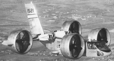
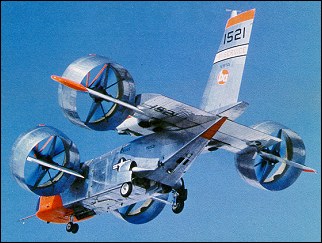
The X-22A was designed for evaluation of the tilting-duct concept in an airframe that might form the basis of a light V/STOL transport. It was also designed to provide a versatile platform capable of general research on V/STOL handling qualities using a variable stability control system. The Tri-Service V/STOL Transport Program addressed needs of the Army, Navy, and Air Force, to develop a small number of prototype V/STOL transport aircraft that used different concepts and to perform operational evaluations of their usefulness. The Navy studies showed that a duel tandem ducted fan configuration permitted a shorter wing span for a given weight, allowing a stubbier design that could fit on existing carrier elevators and would eliminate the need for complex wing folding mechanisms. The duct around each of the four props also would improve propeller efficiency and provide a safety benefit to personnel working on a ship’s flight deck. The Navy awarded a $27.5 million contract for the design and development of two identical X-22s to Bell Helicopter of Niagara Falls, NY, in November 1962. Bell’s internal designation was the Model D2127. Bell had already Bell built and flew the Air Test Vehicle and X-14 VTOL research aircraft. Representative of a possible small V/STOL transport, the X-22 could carry a 540kg payload and could carry up to six passengers. Its length and wingspan were each a little over 11.9m, and maximum gross weight was 7530kg.
The rectangular fuselage accommodated at its rear a wide-chord wing fitted on its leading edges with two groups of two 1250-shp (932-kW) General Electric YT58-GE-8B/D turboshafts to drive four propellers (or fans) located inside annular ducts. These last were located at the tips of the wings and the short span foreplane and could be turned between the vertical (for vertical take-off and landing) and the horizontal (for forward flight). Change in the propeller pitch produced the thrust modulation for control, and was supplemented by movement of aileron in the slipstream of each duct. The “B” and “D” designations on the engines referred to two engine configurations that differed only by their fuel controllers. They powered a common drive shaft that turned all four props. These engines had both controllers and switched between them automatically based on whether the X-22 was operating in hover mode or cruise mode. 465 gallons of useable fuel was carried in fuselage tanks. The power transmission system consisted of a total of ten gearboxes. It reduced the engine’s nominal 19,500 revolutions per minute speed down to the propellers’ nominal 2,600 revolutions per minute. This arrangement also allowed all four props to continue operating with any number of engines failed or intentionally shut down. The four Hamilton Standard propellers, 2.1m diameter, 3-bladed props were fabricated of fiberglass bonded to a steel core, making them 25 percent lighter than metal props yet giving them three times the fatigue strength. A nickel sheath was mounted over the leading edge. Very high prop efficiency was achieved by placing the props inside of the ducts, so much so that the X-22 could still take off on three engines, fly on two, and make a conventional landing with only one. The two forward ducts were mounted to small pylons on the forward fuselage, and the two rear ducts were mounted to stubby, dihedralless wings on the aft fuselage. Hydraulic actuators rotated each of the four ducts, but mechanical and electrical interconnections insured that all rotated together. Thrust control could be obtained by varying the blade angle. Four elevens, one placed at the rear of each ducted fan assembly, were the only control surfaces. Placing the elevons in the prop slipstream made them very effective, even at low airspeeds. Despite the significant looking vertical stabilizer, there was no rudder. Movement of the elevons and changes to the prop pitch achieved all flight control. Flight control in horizontal flight was achieved using a conventional looking control stick for pitch and roll. Moving the stick caused the elevons to move, either differentially between the front and rear for pitch, or differentially on left and right sides for roll. Yaw was achieved by moving the rudder pedals, which changed the propeller blade angles to produce differential thrust. There were also throttles for each engine and a lever to control the angle of the ducts. In forward flight, the front ducts were rotated to 3 degrees up from horizontal and the rear ducts rotated to 2 degrees below horizontal. This gave an optimum incidence of 5 degrees between the two pairs. The cockpit arrangement included two zero-zero ejection seats set side-by-side, full conventional instrument displays (plus a master tachometer for propeller revolutions and a duct angle indicator) duplicated for each pilot. Engine controls were gathered on the central console. While hovering, the pilot used the same control stick to control pitch and bank motions. Stick inputs caused the flight control computer to command minute changes to the prop blade angles to vary the thrust, causing the X-22 to tip forward, aft, or sideways. Yaw was controlled by moving the rudder pedals, by differential movements of the elevons between the left and right sides. The pilot also could rotate the ducts to assist the fore/aft motion during hover. During transition, with the ducts at some intermediate angle, the pilot’s control inputs produced mixed propeller pitch and elevon deflections. The ratio of mixing between the props and elevons was a function of the duct angle. The ducts rotated at 5 degrees per second. The X-22’s flight controls also included a variable stability system. This was another flight control computer that modified the basic airplane responses so that the characteristics of other aircraft, either real or imagined, could be produced. The variable stability system followed algorithms that were developed specially for each test and programmed into the computer. They produced extra control surface motions that caused the X-22’s flight characteristics to be varied, thus producing motions that are not characteristic to the X-22 airframe, but rather to the aircraft being simulated. This gave the X-22 the capability to perform research that would be applicable to a broad range of other aircraft, not just the unique characteristics of the X-22 itself. The Cornell Aeronautical Laboratory designed the variable stability system. The first X-22, US Navy Bureau Number 151520, rolled out on May 25, 1965, and was followed by fifty hours of propulsion tests in a test stand. The flight test program was undertaken by Calspan Corporation, in Buffalo, New York, under the auspices of the U.S. Navy. The first flight in hovering mode was not made until March 17, 1966. On this 10-minute flight, four vertical take-offs and landings and a 180 degree turn were made. It then performed a series of STOL take-off and landing tests with the ducts tilted at 30 degrees. The first X-22 was damaged beyond repair on its fifteenth flight on August 8, 1966. It had flown only 3.2 hours, but suffered a dual hydraulic failure about four miles from its base at Niagara Falls Airport. The first transition from wing-borne flight to vertical flight was made under the stress of an emergency landing. The fuselage broke in half, with the rear section coming to rest inverted. While the aircraft was lost, neither pilot was injured. Swivel fittings were used in the ducts to provide hydraulic fluid to the elevon actuators. Both failed due to excess vibration. The fix included replacing the swivel fittings with loops of flexible tubing, replacing the aluminum hydraulic lines with ones made of stainless steel, and placing additional clamps on the hydraulic lines to minimize vibration. The first was damaged beyond economical repair and it was cannibalized to keep the second aircraft flying, although the fuselage was retained for use as a ground simulator at Calspan. The second X-22, BuNo 151521, rolled out took place on 30 October, 1965 and flew on 26 January, 1967, with Stanley Kakol and Richard Carlin in the cockpit, for a first 10-minute hover flight. Bell test pilots Stanley Kakol and Paul Miller were at the controls. The first transition being successfully made on 3 March. With pilots from Bell, the Army, Navy, and Air Force, the X-22 flew frequently over the next several years. At the completion of the Tri-Service testing in January of 1971, the X-22s completed 228 flights, 125 flight hours, performed over 400 vertical take-offs and landings, over 200 short take-offs and landings, and made over 250 transitions. It also hovered at 2440m of altitude and achieved forward speeds of 507km/h. These flights demonstrated that the X-22 had good basic stability and that vertical take-offs and landings could be performed easily. Operation in ground effect was a little less stable, but still positive. Hovering was easier than in most helicopters. In horizontal flight, all responses to pilot control inputs were excellent. Transitions were accomplished with minimum pilot workload. Landing position could be controlled precisely. The aircraft was still controllable without augmentation, but required a significant increase in pilot workload. This system provided rate damping in pitch, roll, and yaw only during hover and low speed flight. With the Navy satisfied with the basic operation, they awarded a contract to Cornell in July 1970 to operate and perform flight research using the X-22, with particular emphasis on operating in the variable stability mode.
Over the next ten years, Calspan flew five test programs:
August 1971 – February 1972: evaluation of steep STOL approach paths of 6-10 degree glide slopes, at airspeeds of 120-150km/h, with a variety of oscillatory characteristics in the pitch mode. June 1972-February 1973: continuation of previous effort, but with variation of roll and yaw oscillatory characteristics.
October 1973 – April 1975: evaluation of control, display, and guidance requirements for STOL instrument approaches. Determined desirable control system requirements and information displays for pilot use to permit transition from forward flight to a decelerating steep approach and then to a hover at 30m, followed by a touchdown, all under instrument conditions.
February 1977 – March 1978: expanded the previous experiment by evaluating the usefulness of a head-up display for STOL instrument approaches. Used precision radar distance measuring equipment to establish the aircraft’s position within 7.62mm. Evaluated a variety of display formats that presented data to the pilot, such as attitude, airspeed, altitude, horizontal location, and range to touchdown. Also, simulated the AV-8B, a specific aircraft, rather than a generic set of aircraft characteristics.
November 1978 – May 1980: generated flying quality and flight control design requirement data for V/STOL aircraft performing shipboard landings. In performing this task, typical shipboard pitching and rocking motions had to be added to the guidance beam, then various compensation schemes were programmed into the flight computer on the X-22. Hover, and then simulated touchdowns at 30m were performed.
Numerous problems were discovered and fixed during testing. While all were fixed, they were not necessarily fixed in an optimum manner, as would be done for a production aircraft. Further development may have provided an optimal solution. But, being a research aircraft, a fix that worked for the intended mission was good enough. Some of them included the following:
Failure of the linkage synchronizing the front and rear duct angles, resulting in the front ducts rotating to 30 degrees while the rear ducts remained vertical. Fortunately, this happened on the ground. The aluminum shaft that transmitted the proper duct angle was replaced with one made of stainless steel.
In forward flight with the ducts near the stall angle of attack, the airflow from the lower lip separated from the duct surface as it entered the duct, causing a very loud buzzing as the turbulent flow hit the prop. Installing a number of vortex generators on the bottom inner-lip of each duct reduced this problem significantly.
A number of fatigue cracks developed on the inside of the duct skin and ribs. Apparently this was caused by a wake of very low pressure being pulled behind each prop blade. Thus, for each revolution of the prop, the surface was hit with three pulsations of high, then low pressure. This was corrected by replacing the ribs with slimmer ones, then building up an eighteen-inch wide ring of fiberglass inside each duct, maintaining the 0.95cm clearance between the prop tip and the wall. The program office within the Navy that oversaw the X-22’s testing was disbanded. Calspan sought added research programs, but the most they could accomplish was to get the Naval Test Pilot School to use the aircraft for some V/STOL demonstration flights for their students during 1981 and 1982. The aircraft made its last flight in October 1984. Ownership was transferred to the Naval Aviation Museum at Pensacola, Florida, but the museum never had any desire to display unique aircraft that were not typical of Naval aviation use. The X-22 remained in storage at Calspan’s facility at Buffalo Airport in hopes that further projects would return this unique test vehicle to service, or at least be acquired by an aviation museum. No further work ever arose, and many efforts to transfer the X-22 to an appropriate museum in the western New York area fell through. In 1995, Calspan moved it outdoors because they needed the hangar space. To protect it from the elements, the Buffalo & Erie County Historical Society paid to cover the X-22 in a plastic wrapping. In 1998, the newly formed Niagara Aerospace Museum at Niagara Falls, NY, acquired the X-22 and placed it on display.
For two full years, the X-22A was involved in a flight-test programme with Bell and the NASA. During this period some 220 flights and 110 flying hours were logged. This phase was followed, in January 1968, by a first military preliminary evaluation during which the X-22A was examined by pilots and engineers of the three Services and accomplished fourteen flights. A second military evaluation took place at the beginning of the following April. During this period, the X-22A demonstrated. good performance such as a sustained hover at an altitude of 2400m. On 19 May, 1968, the X-22A was officially taken on charge by the US Navy which turned it over almost immediately to Calspan Corp responsible for the test programme on behalf of the Navy. The prototype had been equipped with an automatic flight control system known as LORAS (Linear Omnidirectional Resolving Airspeed System). This programme, which was broken down into several tasks, totalled 273 flights, 279.9 flying hours, 130 VTOL take-offs and 236 VTOL landings. The aircraft was flown until the autumn of 1984 when flight testing was considered terminated. The X-22A made its last flight in 1988.
Engines: 4 x General Electric YT58-GE-8B/D turboshaft, 932kW / 1250hp Wingspan: 11.96m / 39 ft 3 in Length: 12.06m / 39 ft 7 in Height: 6.3m Take-off weight: 8172kg Empty weight: 4302kg Max speed: 370 km/h Cruising speed: 343km/h Range: 716km Ceiling: 15,000 ft. Fastest Flight: 255 mph Total Flights: 500+ Highest Flight: 27,800 feet (approx)
Bell was responsible for design and construction of the Model 47, the first helicopter to receive Approved Type Certificate from the U.S. Civil Aviation Authority (on March 8,1946), and which remained in production for more than 25 years. Later helicopters of particular importance included the UH-1 Iroquois (Model 204) military utility helicopter (first flown October 1956), and the world’s first purpose-designed tandem two-seat attack helicopter, the Model 209 (military AH-1 HueyCobra), first flown September 1965 and operated by the U.S. Army in Vietnam from 1967. Production of HueyCobra in the U.S.A. ended, but Fuji in Japan still produced examples in the AH-1S version. Bell programs include remanufacture of 180 AH-1W SuperCobras and 100 UH-1Ns of U.S. Marine Corps into AH-1Zs and UH-1Ys respectively under the H-1 Program, with upgrades common to both helicopter types including the installaton of General Electric T700 engines, four-blade composite hingless and bearingless rotors, and much more besides; upgrade and life-extension of UH-1Hs of other forces to UH-1H-II or Huey II standard (joint Bell and AlliedSignal program) by installation of AlliedSignal T53-L-703 turboshaft engine plus airframe improvements; production of the twin-turboshaft AH-1W SuperCobra for the U.S. Marine Corps (introduced 1986); and upgrade of 411 U.S. Army 0H- 58 Kiowa reconnaissance helicopters to OH-58D Kiowa Warrior armed configuration (also for Taiwan). Also development and production of the BA 609, a civil tiltrotor transport in association with Agusta of Italy, after Boeing’s share in the program was passed to Bell). Bell participates in the Bell Boeing V-22 Osprey military tiltrotor program (first flown March 1989) to provide the U.S. forces with a vertical-lift transport and multipurpose aircraft capable also of strike, rescue, amphibious combat assault, and anti-submarine work. Bell Helicopter Company, originally a division of Bell Aircraft, became a branch of Textron Inc. in 1960 and a fully-integrated subsidiary in January 1982. Bell Helicopter Textron Inc. is its current name; Bell has produced well over 33,000 helicopters. In 1986 commercial/civil helicopter production moved to Canada. Came to an agreement with IAR-SA Brasov in 1996 to allow license manufacture of AH-1W SuperCobra in Romania, tied with the purchase of a majority shareholding in IAR-SA Brasov. A subsidiary of Textron Inc in the USA and Canada. 1995: Bell Helicopter Textron, PO Box 482, Fort Worth, TX 76101, USA, and Bell Helicopter Textron Canada, 12800 Rue de l’Avenir, St Janvier, Quebec J7J 1R4, Canada. Bell Helicopter Canada was founded in 1984, with a production factory at Mirabel completed 1985 as a division of Textron Canada Ltd. Manufacture of Bell Helicopter Textron Inc. commercial/civil helicopters moved from U.S.A. to Mirabel 1986, leaving U.S. company free to concentrate on military types. Production encompasses Model 206B-3 JetRanger III five-seat light helicopter (first flown 1962 in original form and 1977 as JetRanger III) and its TH-67 military trainer variant; seven-seat Model 206L-4 LongRanger IV (first flown 1974 in original form and certificated 1992 as LongRanger IV); Model 206LT TwinRanger as twin-turboshaft variant of LongRanger (certified 1993); 15-seat Model 212, using twinned turboshafts; Model 230 intermediate- twin ten-seat helicopter (first flown August 1991); Model 407 extra-wide variant of LongRanger with a fourblade main rotor (first flown June 1995); Model 412EP 15-seat utility helicopter, also suited to specialized roles such as law enforcement, SAR, and medical (first flown 1979); Model 427 eight-seater (first flown December 1997) as a lengthened version of Model 407; and Model 430 derived from the Model 230 but with more engine power and a four-blade bearingless composite main rotor (first flown October 1995).
In 1952 Agusta was granted a license to build Bell Model 47 helicopters. First Agusta-built example flew May 1954, and over 1,200 were built before production ended in mid- 1970s. The company also produced Bell Iroquois models as Agusta-Bell 204B and 205, twin-engined Model 212 (still offered as AB-212 Naval/Skyshark) and Model 206 JetRanger (still offered as AB-206B JetRanger III) helicopters. In 1967, under Sikorsky license, production of SH-3D helicopters began, and in 1974 production of HH- 3F (S-61R); production of final HH-3F Combat SAR version lasted into mid-1990s. Together with Elicotteri Meridionali, SIAI-Marchetti, and other Italian companies, Agusta became involved in production of the Boeing Vertol CH-47C Chinook. Other license-built helicopters include AB-412EP/Griffon/Maritime Patrol versions of the Bell 412EP and Griffon, AMD-500E version of the McDonnell Douglas (now Boeing) MD 500E, and Agusta-Boeing 520N NOTAR helicopter.
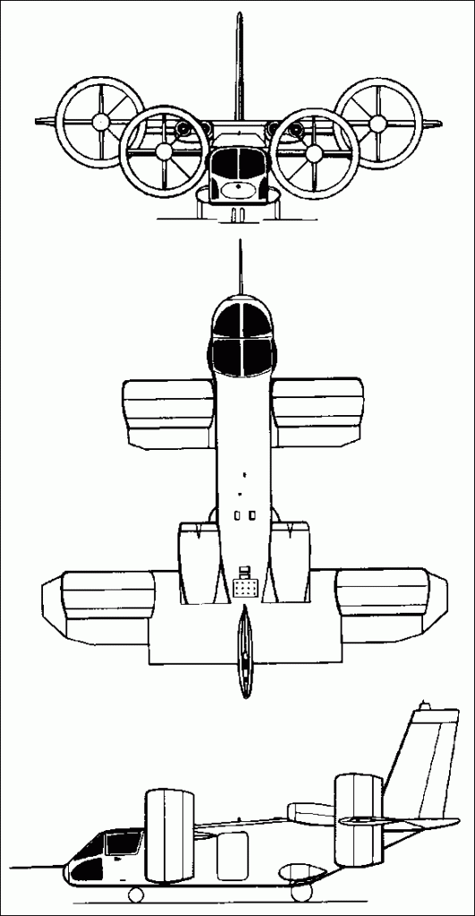
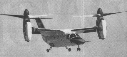
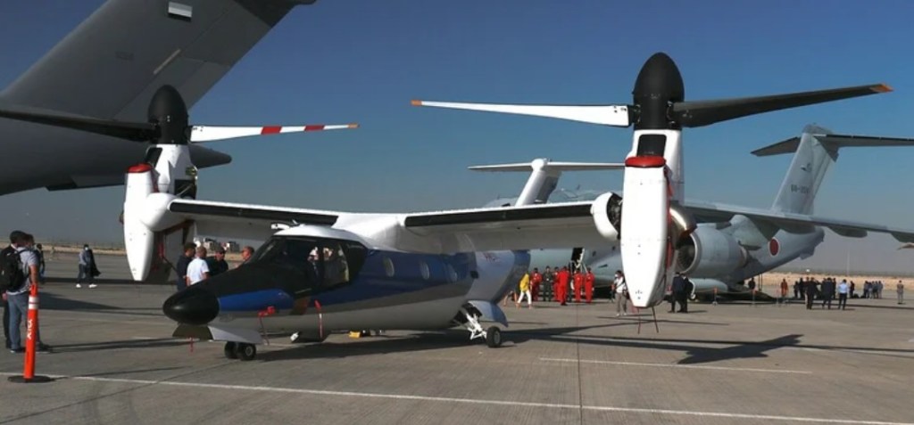
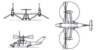
Bell and Boeing revealed in February 1996 that studies were in progress for a nine-passenger civil tiltrotor aircraft in the 6,350kg weight class, with the preliminary designation D-600. On 18 November 1996, the two companies announced that a joint venture was being established to design, develop, certify and market a six- to nine-passenger civil tiltrotor as the Bell Boeing 609. The machine has engines which pivot 90 degrees so it can take off vertically like a helicopter, then fly horizontally like a plane. Boeing withdrew as a partner on 1 March 1998 and Bell formally announced at the Farnborough Air Show in September 1998 that they had teamed with Agusta. Agusta was investing and participating in BA609 development and was to be responsible for assembly of BA609s sold in Europe and elsewhere. Preliminary design review completed May 1997. Manufacture of parts for the prototypes began in Philadelphia, August 1997, and a full-size mockup was exhibited at the Paris Air Show in June 1997. With a T-tail configuration and composite cross-shafts to keep both prop rotors turning in event of engine failure. Manual screwjack facility exists whereby the prop-rotors can be tilted into helicopter mode if the cross-shafts fail. Designed using three-dimensional CATIA digital computer design system, the airframe has design life of 20,000 flight hours. The aluminium fuselage structure has composites skinning and composites wings. The undercarriage is a retractable tricycle type, with twin nosewheels and single wheel on each-main unit. Control is by a BAB Systems triplex digital fly-by-wire flight control system, with Dowty Aerospace actuators. The T tail has conventional elevators and no rudder. Two-segment trailing-edge flaperons are fitted. Two 1,447kW Pratt & Whitney Canada PT6C-G7A turboshaft enginesc are installed in tilting nacelles at the wingtips, each driving a three-blade proprotor. Nacelle transition is achieved in 20 seconds. Fuel is in integral wing tanks with a usable capacity of 1,401 litres, and provision for auxiliary fuel tanks. The airframe carries a crew of two, side by side on flight deck, with dual controls, and a maximum of nine passengers in the standard aircraft. A crew and passenger door is on the starboard side, forward of wing. The cockpit is pressurised and air conditioned; pressurisation differential 0.38 bar. Ground-running trials began on 6 December 2002 and the first flight of the prototype (N609TR) took place (in the vertical mode only) on 7 March 2003 in Arlington, Texas, rescheduled from late 2002. The Bell/Augusta Aerospace Co said its BA 609 tilt-rotor aircraft flew at an altitude of about 15m in its first test flight. Four prototypes were produced for a 36-month flight test programme leading to certification in January 2007 under FAR Pt 25 (fixed-wing aircraft) and Pt 29 (helicopters), plus Pt 21.17(b) Special Conditions for unique components. The first prototype were used primarily for expansion of flight envelope, while the second, third and fourth airframes were dedicated to systems certification, avionics and icing approval, and FAA function and reliability, respectively.
Leonardo AW609
The order book opened on the 2nd of February 1997 at Heli Expo, with the first order placed soon after by an unspecified customer. A total of 70 were ordered by 40 customers in 18 countries by March 2003. A briefing was given to the US Coast Guard, late 1997, followed by a demonstration by the XV-15 tiltrotor concept demonstrator aboard the Coast Guard cutter Mohawk off Key West, Florida, in May 1999. In 1998 Bell Helicopter Textron acquired Boeing’s 49% interest in the Bell-Boeing 609 civil tiltrotor and has assumed full ownership.
Bell 609 Engine: 2 x Pratt & Whitney PT6C-67A, 1360kW / 1850hp Empty weight: 6300kg Max speed: 510km/h Range: 1390km Crew: 2 Passengers: 6-9
Formed out of Viking Aviation. Produced Viking from 1984 and supported Eagle agricultural aircraft after purchasing certificate and jigs in 1984. Ceased operations 1988.
Giuseppe Mario Bellanca was born in 1886 in Sciacca, Sicily. As a young man, he attended the Technical Institute in Milan, graduating with a teaching degree in mathematics in 1908. During his quest for a second mathematics and engineering degree, he became enamoured of aviation, and set out to design and build his own airplane. Bellanca’s first aircraft design was a “pusher” aircraft, somewhat similar to the Wright Flyer. Lacking funds for such an endeavor, he joined with two partners, Enea Bossi, and Paolo Invernizzi. The union of the three produced the first flight of a totally Italian-designed and Italian-built aircraft in December of 1909. Bellanca’s second design, was a tractor-type aircraft. Although the aircraft was successfully constructed, it was never flown due to insufficient funds for an engine. At the urging of his brother Carlo, who was already established in Brooklyn, New York, Giuseppe Bellanca immigrated to America in 1911. Before the end of the year, he began construction of his third airplane design, a parasol monoplane. After construction was completed, he took the small craft to Mineola Field on Long Island, NY, and proceeded to teach himself to fly. He began by taxiing. He then, taxied faster, which gave way to short hops. The hops got longer, until, on May 19, 1912, there was not enough room to land straight ahead, and Bellanca had to complete a turn in order land safely. Having successfully taught himself to fly, Bellanca then set about teaching others to fly, and from 1912 to 1916, he operated the Bellanca Flying School. One of his students was a young Fiorello La Guardia, the future mayor of New York City. In return for flying lessons, La Guardia taught Bellanca how to drive a car. In 1917 the Maryland Pressed Steel Company of Hagerstown, MD hired Bellanca as a consulting engineer. While there, he designed two trainer biplanes, the CD, and an improved version, the CE. With the conclusion of WWI, Maryland Pressed Steel’s contracts were cancelled and the company entered into receivership. Thus, the CE never went into production. In 1921, a group of investors lured Bellanca westward to Omaha, NE, in hopes of establishing that town as a center for aircraft manufacture. Before the aircraft could be built, the company went bankrupt, but construction of the aircraft continued under the financial backing of a local motorcycle dealer named Victor Roos. The resultant aircraft, the Bellanca CF, was called by Janes’s All the World’s Aircraft “the first up-to-date transport aeroplane that was designed, built, and flown with success in the United States.” Among the local people helping to build the aircraft was the daughter of Bellanca’s landlord, Dorothy Brown. Giuseppe and she were married on November 18, 1922. Despite its advanced design, the Bellanca CF could not compete with the economics of the time. In the days just after World War I, a surplus Curtiss Jenny could be purchased for as little as $250.00. A Bellanca CF, with a price tag of $5000.00, was just too expensive and the aircraft never went into production. After the disappointment of the CF, Bellanca designed wings for the Post Office Department’s DH-4’s. His new wings were a tremendous improvement over the original design, but only a few aircraft were so modified. In 1925, Bellanca went to work for the Wright Aeronautical Corporation of Paterson, NJ. His assignment there was to develop an aircraft around the new Wright Whirlwind engine. He already had a design in mind, which was an improved version of the CF, called the CG. This design evolved into the Wright-Bellanca WB-1. The WB-1 enjoyed a short, but successful flying career. The aircraft had already won one race and efficiency contest before an untimely accident destroyed the craft during preparation for an attempt to break the world’s non-refueled endurance record. Fortunately, at the time of the crash, Bellanca was already working on an improved version, of the WB-1 designated the WB-2. During 1926, the WB-2 won two efficiency trophies at the National Air Races in Philadelphia. Wright considered putting the aircraft into production, but decided against it to avoid alienating other aircraft companies that were potential customers for their engines. Disappointed by Wright’s decision, Bellanca left the company and joined with a businessman named Charles Levine to form the Columbia Aircraft Company. Wright sold the WB-2 and all drawings and production rights to the new company. The WB-2 went on to a long and fruitful flying career starting with establishing a new world’s non-refueled endurance record of 51 hours, 11 minutes, and 59 seconds in April of 1927. In the latter half of 1926, Charles Lindbergh wanted to buy the WB-2, now named the ‘Columbia’, for his proposed flight from New York to Paris. He was rebuffed by Levine who also had designs on the flight and the $25,000 prize money. Lindbergh then went to Ryan for his “Spirit of St. Louis”. Meanwhile Levine, in choosing the crew, managed to promise two seats to three people. So while the Columbia was grounded by a court order brought by the third party, Lindbergh took off on his successful flight to Paris. Eventually, the ‘Columbia’ was cleared of litigation and took off on its successful transatlantic flight on June 4, 1927. In the cockpit were Clarence Chamberlin, one of the pilots of the endurance record and Charles Levine, who became the first transatlantic passenger. The plan was to fly all the way to Berlin, and Chamberlin had vowed to fly until they ran out of fuel. Forty-three hours later, they landed in Eisleben, Germany, the first of two successful Atlantic crossings for Bellanca’s most famous aircraft. Disappointed because the ‘Columbia’ was not the first aircraft to accomplish the New York to Paris flight, Bellanca severed all relations with Levine, and started his own company, the Bellanca Aircraft Corporation of America, and rented facilities on Staten Island, NY. The new Bellanca model was designated the CH, and was basically a commercial version of the WB-2. The new company also had two other models that were built for special orders, the Bellanca Model J and the Model K. It was not long before Bellanca caught the attention of the Du Pont family of Delaware. They wanted to start aircraft manufacturing in Delaware, and in late 1927, an agreement was made with Bellanca to locate his factory outside of Wilmington. The site was large enough for a first-class airfield, with a seaplane ramp on the nearby Delaware River. This was a busy time in Bellanca’s life. Along with all that was happening in his professional life, he and Dorothy celebrated the birth of their son August T. Bellanca in March of 1927. With the exception of a few years immediately before and during the early stages of WWII, Bellanca was President and Chairman of the Board from the corporation’s inception on the last day of 1927 until he sold the company to L. Albert and Sons in 1954. All assets were acquired by Northern Aircraft in 1955 and Bellanca name finally dropped 1959 after merger with non-aviation companies. After his departure from the company, Giuseppe and his son, August, formed the Bellanca Development Company with the purpose of building a new aircraft. It would have increased performance due to the use of lighter materials for its structure. Work on this aircraft was progressing when Giuseppe Bellanca succumbed to leukemia and died on December 26, 1960. After his father’s death, August continued the project, and under his guidance, the aircraft, a record breaker, first flew in 1973. Northern Aircraft became Downer, then Inter-Air, and in 1967, Bellanca Sales, a subsidiary of Miller Flying Services. As the company grew, its name became Bellanca Air¬craft Corporation. Champion Aircraft Corporation was merged into it in 1970, adding two place aerobatic, sport and utility aircraft to the line. 1974 closed with the firm still in the busi¬ness only of building Vikings in Alexandria and Champi¬ons in Osceola, Wisconsin, and with sales slowing a bit. In late 1974, Bellanca was forced to suspend production in order to work off an in¬ventory of airplanes. In 1978 Bellanca became a wholly-owned subsidary of Anderson, Greenwood, of Houston, Texas, subsequently developing the T-250 Aries and Eagle. Work stopped in 1980 and the firm liquidated in 1981. Assets were sold to Viking in 1982. Viking resumed Viking production in 1984. Work stopped in 1988. The original Bellanca company was restarted by Guiseppe Mario Bellanca and son August in 1968, initially in West Virginia and later Maryland. Work stopped in 1986. The firm was resurrected as AviaBellanca. In 1993, August Bellanca donated his father’s 1920 CF to the Smithsonian along with many personal and corporate papers and correspondence. NASA craftsmen restored the aircraft and it is on display at the Smithsonian Air & Space Museum’s new Steven F. Udvar-Hazy Center near Washington’s Dulles International Airport. The far-sighted, innovative designer and builder of American aircraft, Giuseppe M. Bellanca was enshrined in the National Aviation Hall of Fame in 1993, the Delaware Aviation Hall of Fame in 1999.
1998: Avia Bellanca Aircraft Corp 11800 Sunrise Valley drive, Suite 322 Reston Virginia 20191 USA
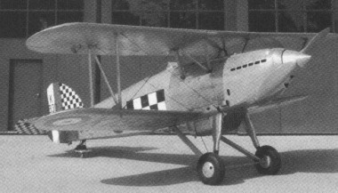
For many years the Fury was ‘extinct’ as a type and so in the early 1980s Viv Bellamy was contracted by the Hon Patrick Lindsay to build a full size Fury replica for him in Cornwall, England. An original Rolls Royce Kestrel was found after much searching in New Zealand (ex Pete Coleman), where it had been fitted to a Hawker Hind. This is a Kestrel V of 640 hp, rather than the Kestrel II of 525 hp the Fury was originally fitted with. After completion, the Fury replica was registered as G-BKBB and painted up as X1930 from 43 Squadron ‘The Fighting Cocks’. Patrick Lindsay was a very ill man, but was able to see the aircraft’s first flight on December 11, 1985 (in the hands of Viv Bellamy) before his death. Cared for by Personal Plane Services at Booker, Buckinghamshire, the aircraft was rarely seen, and rumours of possible show appearances and offers for sale abounded, including a static appearance at Christie’s Auction at IWM Duxford in 1990, where it failed to sell with a reserve of £ 200,000 and less than three hours flying time. Afterwards it was sold to the Belgian Vintage Aircraft Flying Museum. In 1996 it was flown to Belgium and was placed on the Belgian registration as OO-HFU. During an airshow it crashed and was damaged. A rebuild was undertaken in 2001 by Skysport Engineering and a number of test flights were carried out in the UK. The Fury was then based at Old Warden for a short period. In June 2003 Dirk De Slenter flew it back to Belgium and it went in to storage at Kortrijk Wevelgem, it having been decided by the late owner’s family that it was too precious to fly. In 2009 the Fury and its engine was surveyed by a technician for Mr Gerald Yagen and the aircraft was sold from Belgium to Jerry Yagen’s Military Aviation Museum, Virginia Beach, VA, USA, soon after and later shipped to the USA.