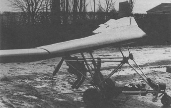
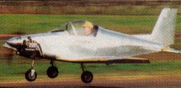
Single seat single engined high wing mono¬plane with conventional three axis control. Wing has swept back leading edge, unswept trailing edge and tapering chord; no tail. Pitch/roll control by stabilator; yaw control by tip rudders; control inputs through stick for pitch/roll and pedals for yaw. No external wing bracing; wing profile 100% double¬surface. Undercarriage has three wheels in tricycle formation; no suspension on any wheels. Flush right go right nosewheel steer¬ing connected to yaw control. No brakes. Aluminium tube framework, without pod. Engine mounted below wing driving pusher propeller. All tubing and bolts are to aircraft specification. Dave Bremner’s home¬built special uses a standard Mitchell B10 wing, the rest of the aircraft being to his own design. Certainly the most unusual aspect of the aircraft is its engine, a Suzuki twin from the GT185 motorcycle. Originally the aircraft was fitted with a 210 cc Villiers kart engine, but this suffered from two disadvantages: first it was difficult to arrange a suitable engine mounting system, and second it could only be started by swinging the prop. Dave’s search for a replacement led him to the GT185, which he chose because it has integral electric start and a horizontally split crankcase, allowing the gearbox to be re moved without expensive machining. In most respects he has built a fairly conventional machine, the cage being based on photographs and sketches of Mitchell’s own. There is no braking or suspension and the pedals are arranged so that both tip rudders can be deployed simultaneously to provide air braking. There were no plans to market the aircraft.
Engine: Suzuki GT 185, 20 hp at 6800 rpm. Propeller diameter and pitch 50 x 27 inch, 1. 28 x 0. 70 m. V belt reduction, ratio 3.0/1. Max static thrust 90 1b, 41 kg. Power per unit area 0.15 hp/sq.ft, 1.6 hp/sq.m. Fuel capacity 2.4 US gal, 2.0 Imp gal, 9.1 litre. Length overall 8.0ft, 2.44m. Height overall 4.8ft, 1.46m. Wing span 34.0ft, 10.36m. Chord at root 5.0ft, 1.52m. Chord at tip 1.3ft, 0.40m. Dihedral 6 deg. Sweepback 6 deg Rudder height 1.0 ft, 0.30 m Total wing area 136 sq.ft, 12.6 sq.m. Total stabilator area 12.0 sq.ft, 1.11 sq.m Rudder area 4.0 sq.ft, 0.37 sq.ft Wing aspect ratio 8.4/1. Wheel track 5.0 ft, 1.52 m Wheelbase 3.5 ft, 1.07 m Nosewheel diameter overall 10 inch, 254 mm Main wheels dia¬meter overall 16 inch, 406 mm Empty weight 242 lb, 110kg Max take off weight 492 lb, 223kg Payload 250 lb, 113 kg Max wing loading 3.67 lb/sq.ft, 17.9kg/sq.m Max power loading 24.61b/hp, 11.0kg/hp
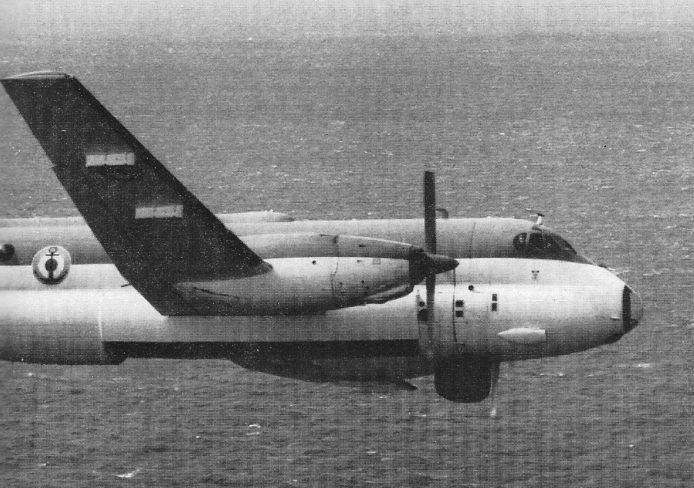
When the specification was outlined in January 1958, designs were submitted to NATO and by the end of 1958, the Breguet Br 1150 had been selected as the best of the projects. The choice was endorsed by all 15 nations in NATO, including the USA, Canada and the UK. A joint develop¬ment contract was drawn up in February 1959, which provided for work on the Br 1150 to be financed by Belgium, France, Germany, the Netherlands and the USA, although only France and Germany were at that time indicating an interest in acquiring the new MR type in operational quantities. Belgian and Dutch interest was maintained as a means of obtaining a share in the production programme for indigenous companies, while US financing was part of that nation’s general support for NATO. To handle the joint design and production of the Br 1150, for which the name Atlantic had been adopted, Societe d’Etude et de Construction de Breguet Atlantic was set up as the industrial executive agency, the original constituent companies of which were Breguet, Sud Aviation, ABAP (the Belgian grouping of SABCA and the then Fairey company), Fokker and Seeflug (the German grouping of Dornier and Siebel). Engines, propellers and the radar ECM system were to be government funded equipment (GFE) but were also made the subject, so far as possible, of European joint production programmes. The Rolls Royce Tyne RTy 20 Mk 21 was selected to power the Atlantic, production being under licence in France by SNECMA (with a 44 per cent share) and contributions by MTU in Germany (28 per cent), Rolls Royce (20 per cent) and FN in Belgium (8 per cent). The Hawker Siddeley Dynamics (de Havilland) propeller was put into production by Ratier. CSF was chosen to produce the radar in France and other major suppliers were Hispano Suiza for the undercarriage, Crouzet for navigation equipment and Bendix, Sperry and Canadian Marconi for avionics items.
To launch the programme two prototypes were ordered in July 1959, and the basic industrial programme for the prototype and production stages was agreed in December. The first prototype, powered by RTy 20 engines supplied completely by Rolls Royce, flew at Toulouse on 21 October 1961. It was followed by the second (Atlantic 02), which flew on 25 February 1962, but was lost in an accident two months later, on 19 April. Meanwhile, two pre-¬production examples had been ordered in February 1961; the first of these (Atlantic 03) flew on 25 February 1963 and featured the lengthened fuselage that had been adopted for the production model, 3 ft 3 in (1 m) longer than the prototypes. Other features of the production standard Atlantic, for which orders were placed in June 1963, were incorporated in the second pre production Atlantic, 04, which flew on 10 September 1964 and subsequently being referred to as the first production model. This same aircraft was eventually to be used, in 1979, as an aerodynamic test vehicle for the Atlantic NG (in which guise it was known as the ANG 001). The initial phase of flight test and development was completed on 31 October 1965, with some 2,000 hrs of flying, and on 10 December that year the first production Atlantic for the French Aeronavale and the Federal German Marineflieger were handed over in a formal ceremony at Nimes Garons. By the end of the year, five aircraft were off the line and production was at a rate of two a month. Production was shared between France (60.5 per cent by value of the airframe), Germany (17 per cent), the Netherlands (15 per cent) and Belgium (7.5 per cent). In practice, the work was divided between Sud Aviation (outer wings), Breguet (front and centre fuselage plus final assembly at Toulouse (Colomiers), Dornier (rear fuselage and lower lobe of centre fuselage), SIAT (tail unit), SABCA (power plant cowlings), Fairey (centre section flaps) and Fokker (centre section structure and nacelles).
Between 1965 and 1968, Aeronavale received 40 Atlantic Is and Marineflieger, 20. In France, these aircraft were issued progressively to four Flottilles, Nos 21F and 22F based at Nimes Garons and operating in the Mediterranean area, and Nos 23F and 24F based at Lann Bihoue and operating over the Atlantic. The front line strength of each of these Flottilles is seven aircraft. Late in 1975, the Aeronavale released three of its Atlantics for sale to Pakistan and these are now based at Karachi for operation by the naval aviation element of the Pakistan armed forces.
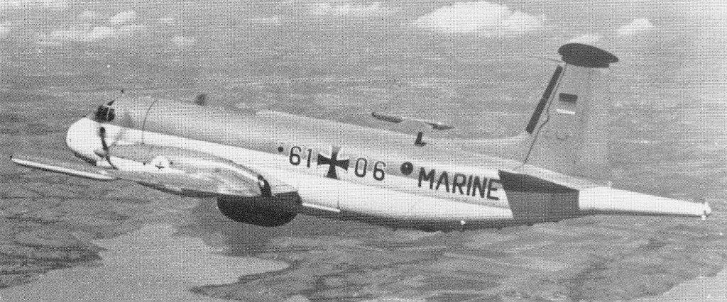
In the Marineflieger, the Atlantic replaced the Fairey Gannets operated in the ASW role by Marineflieger-geschwader (MFG) 3 “Graf Zeppelin” at Nordholz. Of the 20 aircraft acquired, five were converted by LTV for special electronic intelligence (ELINT) duties over the Baltic (one of these having subsequently been lost). Early replacement of the 15 Atlantic Is in the ASW role having been ruled out on financial grounds, the Marineflieger embarked in 1978 on a programme to update the avionics and sonar equipment in the existing fleet, all of which will have been cycled through the so¬called KWS modernisation programme by Dornier GmbH at Friedrichshafen by 1983. Dutch interest in the Atlantic crystallised towards the end of 1960, just as production of the initial run of 60 was completed; purchase of nine was linked to the formation of a new squadron to help replace the aircraft carrier Karel Doorman, and as the need was urgent Avonavale released four of its Atlantic Is for early use by the MLD pending deliveries from the re opened production line. With the Dutch designation SP 13A (the MLD, unlike its land based counterpart the KLu, assigns its own designations to its current aircraft), the Atlantics were issued to VSQ 321 (No 321 Squadron) based at Valkenburg, and were supplemented by the five new production aircraft by January 1972. Meanwhile, Italy’s Marinavia (or A viazione per la Marina Militare) had also decided to adopt the Atlantic 1 and had ordered 18. This brought Aeritalia into the SECBAT partnership, with responsibility for producing (on the finat batch of aircraft) the moving control surfaces, rear fuselage lower lobe, parts of the front fuselage and the engine nacelles. The final batch of aircraft included not only the 18 for Italy but the four replacement Mk Is for Aeronavale to make good those transferred to MLD. Delivered between June 1972 and July 1974, the Italian aircraft entered service with two Stormi Anti¬Somergibile, the 30o Stormo (86o Gruppo) at Cagliari Elmas and the 41o Stormo (88 o Gruppo) at Catania Fortanarossa, each with nine aircraft. Marinavia provides half the crews for these two squadrons, but since 1978, control of land based ASW aircraft has been assigned to the AMI (Italian Air Force) rather than the Navy. On July 19 1974 the Toulouse-Colomiers plant of Dassault/Breguet Aviation delivered the 18th Breguet 1150 Atlantic maritime patrol aircraft to the Italian Government. This delivery ended the first production phase involving 87 Atlantics. The 87 Atlantics delivered are absolutely identical. Delivery schedule was as follows: 40 for the French Navy, 20 for the German Navy, nine for the Dutch Navy and 18 for the Italian armed forces. Improved versions of the basic Atlantic 1 were under study as early as 1972, with the primary objective of expanding the aggressive roles of the aircraft to include anti shipping strike as well as the primary anti submarine mission, and of improving its performance. The French government decided, on 23 February 1978, that the programme should go ahead, and two prototypes of the ANG were duly ordered from Dassault Breguet on 21 December 1978 (these to be conversions of Atlantic I airframes). Destined to become the first prototype (ANG 01), the Atlantic 1 No 42 arrived at Toulouse on 17 July 1979, and made its maiden flight after conversion on 8 May 1981; the second prototype (ANG 02) was a conversion of Atlantic 1 No 69. Breguet, in the original Br 1150 design, a mid wing layout that provided good flotation characteristics in case of ditching, with a two lobe or “double bubble” fuselage permitting pressurisation of most of the upper lobe and an unobstructed cabin of constant width over a length of nearly 50 ft (15 m), with a weapons bay in the unpressurised lower lobe some 27 ft in length. The mid wing position also allowed the weapons bay doors to open by sliding up the sides of the fuselage, thus avoiding obstruction of the panoramic search field of the radar, with its antenna in a retractable radome ahead of the bay, and keeping drag to a minimum with the doors open; loading of weapons also was facilitated by this weapon door arrangement. The Atlantic’s wing was designed with a relatively high aspect ratio of about 11:1, producing a good economy in cruising flight and excellent manoeuvrability at low altitude. The wing was a three spar structure with powered ailerons, slotted flaps, air brakes above and below each half wing and three spoiler segments ahead of the flaps each side. The tail unit included conventional powered control surfaces and a fixed tailplane, with ECM sensors in a fairing atop the fin. The undercarriage had twin wheels on each leg, with the nosewheel retracting to the rear and the main wheels retracting forwards. An APU was located in the forward starboard side of the lower fuselage to provide compressed air for engine starting and ground air conditioning, plus emergency electrical services. Breguet chose turboprop power, electing to use a pair of Rolls Royce Tyne RTy 20s. Structurally, extensive use was made of bonded light alloy/ honeycomb sandwich material for the wing and fuselage panels. In particular, such sandwich construction, in moulded form, was adopted for the wing torsion boxes (containing the integral fuel tanks), the pressurised upper fuselage lobe, tail unit torsion boxes and doors to the weapons bay and landing gear.
Five West German Atlantic converted by ‘Peace Peak’ E-Systems for electronic reconnaissance
Systems in the Atlantic 1 have been almost totally replaced in the ANG included sonobuoy systems and a CSF magnetometer for submarine detection and tracking. Typically, the two forward racks carried four L4 or eight Mk 44 torpedoes, the centre rack could receive a nuclear depth charge and 10 active sonar buoys would be mounted in the third rack. Four wing strong points usually carried four AS 12 missiles and internal storage was provided for flares, marker buoys, smoke bombs, submarine detection charges and 72 active sonar buoys. A retro launcher in the rear fuselage allowed sonobuoys to be dropped at nil forward speed. In developing the ANG, the objective has been to produce an airframe with a 12,000 hr life with increased operational serviceability. In pursuit of these targets, the structural design of the ANG has been improved in several respects for easier and more economical maintenance and longer fatigue life. The improve¬ments include a refined bonding technique, extended anti-corrosion protection, better jointing between skins and the use of lighter structural materials in some areas, such as the landing gear, without loss of strength. No changes have been made in the power plant, fuel systems, basic flying controls or hydraulic and electric systems. The ANG has Tyne 21 engines that are functionally interchangeable with the Atlantic Mk 1 powerplants, three integral fuel tanks in each wing with two engine driven pumps and two separate fuel systems with crossfeed options. The weapon bay in the ANG is physically the same size as that in the Atlantic 1, and the same range of stores can be mounted on the three transverse carriers: each carrier or bridge can accommodate four Mk 46 torpedoes, four ASW depth charges or bombs of up to 275 lb (125 kg) weight, three 550 1b (250 kg) mines or four ASR packs not all these items can be carried on all three bridges at the same time, but with the rear bridge empty any combination is possible on the forward and centre bridges, ie, up to eight torpedoes, depth charges or bombs. The new feature for the ANG is the provision to carry Aerospatiale AM 39 Exocet ASMs either two on special bridges, or one AM 39 in combination with three torpedoes, this latter representing a likely standard load. Supplementing the internal stores are four wing hardpoints, now of increased capacity 1,650 lb (750 kg) outboard and 2,205 lb (1000 kg) inboard each able to carry an air to-surface missile such as the AS 12 carried by the Atlantic 1. Initial deliveries began in October 1988 to meet a requirement for 42 aircraft to equip four Aeronavale squadrons.
Breguet Br 1150 Atlantique Engine: 2 x Rolls-Royce Tyne R.Ty 20 Mk 21, 6022 shp Wingspan: 119 ft 1 in / 36.3 m Wing area: 1292 sq.ft Length: 104.167 ft / 31.75 m Height: 37.172 ft / 11.33 m Max take off weight: 95917.5 lb / 43500.0 kg Max. speed: 355 kts / 658 km/h Service ceiling: 32808 ft / 10000 m Range: 4860 nm / 9000 km Max endurance: 18 hr at 195 mph / 1000 ft Crew: 12
Dassault Breguet Atlantic NG Power Plant: Two Rolls Royce/SNECMA Tyne 21 turboprops each rated at 5,665 shp at 15,250 rpm for take off (5 min limit) and 5,190 shp at 14,500 rpm for unrestricted continuous operation. Propellers: Ratier built BAe Dynamics four blade variable pitch of 16 ft (4,88 m) diameter. Fuel capacity, 5,086 Imp gal (23120 1t). Max permissible speed, 355 kts (658 km/h) or Mach = 0.70 Max speed, 320 kts (593 km/h) at sea level Cruising speed, 300 kts (556 km/h) or Mach = 0.50 at 25,000 ft (7 620 m) Typical patrol speed 170 kts (315 km/h) Take off run, 5,420 ft (1650 m) ISA at sea level max weight Initial rate of climb, 2,000 ft/min (10,1 m/sec) Ceiling 30,000 ft (9 100 m) Max endurance, 18 hrs. Empty equipped weight, 55,115 lb (25 000 kg) Max fuel load, 40,785 lb (18 500 kg) Military load (ASW), 6,615 lb (3 000 kg) Normal take off weight, 97,885 lb (44 400 kg) Max overload weight, 101,850 lb (46200 kg) Max zero fuel weight, 71,650 lb (32 500 kg). Wing span, 122 ft 7 in (37,36 m) Length, 107 ft 0.25 in (32,62 m) Height, 37 ft 11 in (11,31 m) Undercarriage track, 29 ft 6 in 4 (9,00 m) Wing area, 1,295.3 sq ft (120,34 sq.m) Aspect ratio, 10.94:1. Internal weapons bay, length 29 ft 6 in (9,99 m), width, 6 ft 1012 in (2,1 m), height, 3 ft 314 in (1,0 m), Armament: up to eight Mk 46 homing torpedoes, two AM 39 Exocet ASMs, 12 depth charges, nine 550 1b (250 kg) mines, etc; four wing strong points have combined capacity of 7,715 lb (3 500 kg); rear fuselage bay contains up to 78 sonobuoys. Normal flight crew: 12, two pilots, flight engineer, forward observer, radio navigator, ESM/ ECM/MAD operator, radar operator, tactical co ordinator, two acoustic operators and two aft observers.
ATL.2 Atlantique Engine: 2 x R-R Tyne RT.20 Mk.21 turboprop, 6,100 shp (4549 kW). Installed thrust: 8450 kW. Prop: 16 ft 0 in (4.88 m) dia 4 blade. Wing span: 119 ft 1 in (36.30 m). Length: 104 ft 2 in (31.75 m). Wing area: 1,295 sq ft (120.34 sq.m). Empty wt: 27,500 kg. MTOW: 95,900 lb (43,500 kg). Warload: 3000 kg. Max speed: 645 kph. Initial ROC: 885 m/min. Ceiling: 9100+ m. T/O run (to 15m): 1840 m. Ldg run (from 15m): 1500 m. Fuel internal: 23,120 lt. Range: 1850 km. Endurance: 5 hr on station. Air refuel: No. Cruising speed: 345 mph (556 km/h). Max range: 5,590 miles (9,000 km). Crew: 12.
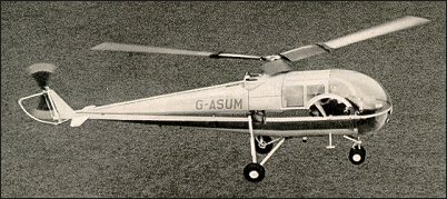
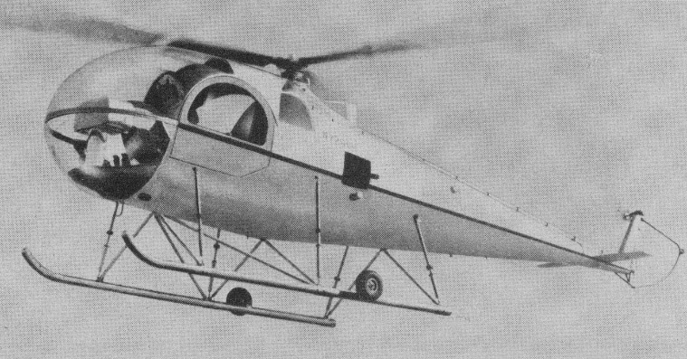
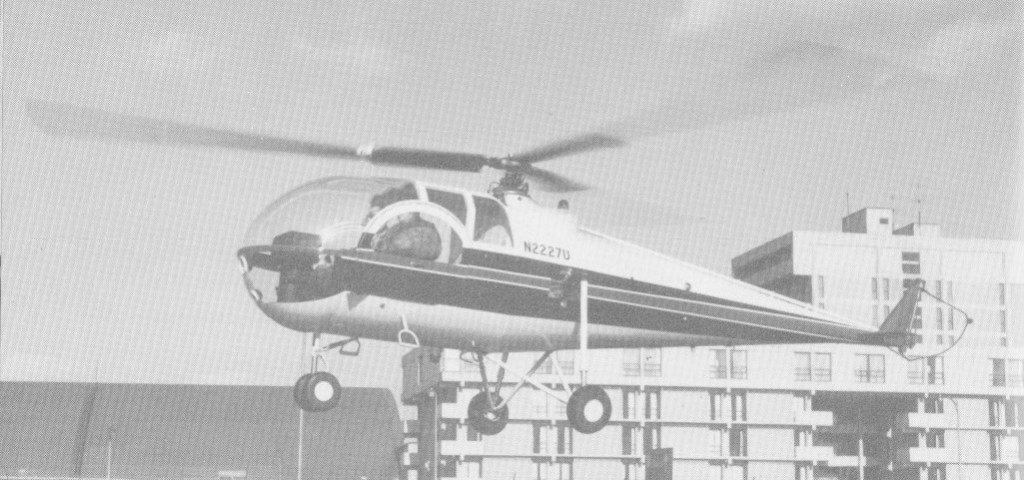
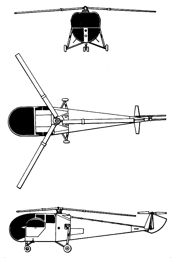
Brantly produced an enlarged B-2, named the Model 305 which had a longer forward fuselage providing a rear 3-passenger bench seat. The new five seater (N2200U) made its first flight in January 1964, powered by a 305hp Lycoming IVO-540-A1A engine and received its type certificate on 29 July 1965. The cabin has two bucket seats forward, seating for three aft, capacity for 200 lb of baggage, can fly 120 mph and sold for $48,900.
Brantly immediately commenced production but the Model 305 suffered from persistent ground resonance problems and they only built 45 examples.
It differs from the B2B externally by having a small variable-incidence tail-plane, and an enlarged cabin accommodates a total of five persons on two side-by-side forward seats, and an aft bench seat for three. The rotor system and airframe was the same as the B-2B, but enlarged and conventional direct mechanical flying controls.
The landing gear was a choice of skid, wheel or float gear. Skid type has four oleo struts, two on each side, and small retractable ground handling wheels. Wheel gear has single mainwheels and twin nosewheels, all with oleo-pneumatic shock-absorbers of Brantly manufacture. Goodyear mainwheels and tyres size 5.00-5, pressure 1.93 bars. Goodyear single-disc hydraulic brakes on mainwheels.
The 227.4kW Textron Lycoming IVO-540-B1A flat-six engine, was mounted vertically, with dual cooling fans. One rubber fuel cell under engine, capacity 163 litres. Refuelling point in port side of fuselage. Oil capacity 9.5 litres.
A rear compartment for 113kg of baggage, with downward hinged door on starboard side.
Model 305
44 were built during the 1960s and another four built by Hynes Aviation in 1985 as the H-5. Michael K. Hynes, owner of the type certificates, established Brantly-Hynes Helicopter Inc. on 1 January 1975, initially to provide product support for the large number of Brantly helicopters in use. He subsequently started up a production line for the B-2B, and also the larger Model 305.
Improved prototype with redesigned rotor head and new blade aerofoil completed about 30 hours flying by mid-January 1990. New main rotor bearing fitted. Cabin streamlined. New production was to begin 1993, but none built.
Engines: Lycoming IVO-540-B1A, 305 hp, 227kW Main rotor diameter: 8.74m Fuselage length: 7.44m Height: 2.44m Disc loading: 4.5 lb/sq.ft. Pwr loading: 9.5 lb/hp. Max TO wt: 1315kg, 2900 lb. Empty wt: 816kg, 1732 lb. Equipped useful load: 1106 lb. Payload max fuel: 854 lb. Range max fuel/ cruise: 199 nm/ 1.9 hr. Range max fuel and payload: 354km Service ceiling: 3660m, 11,000 ft. Max speed: 193km/h Max cruise: 177km/h, 104 kt. Max range cruise: 95 kt. ROC: 975 fpm. HIGE: 4000 ft. HOGE: 1500 ft. Max sling load: 800 lb. Fuel cap: 252 lb. Seats: 5.
Developed from coaxial twin-rotor B-1 by Newby Brantly, the B-2 with single main rotor and anti-torque tail rotor configuration first flew on 21 February 1953. An improved second prototype flew on 14 August 1956. This was to enter production in 1958 receiving FAA certification on 27 April 1959.
1955 B-2
A total of 194 B-2s and 18 B-2As (with additional headroom) were produced between 1960 and 1963 and the improved Model B-2B with metal rotor blades and fuel-injected Lycoming IVO-360-A1A engine was certified on 1 July 1963. A total of 165 were built between 1963 and 1967 (the company owned by Gates Learjet from 1966).
B2A
Type certificates for the Brantly Bs were purchased in 1971 by Michael Hynes and revised as the 2 H2/YHO 3BR. Michael K. Hynes established Brantly-Hynes Helicopter Inc. on 1 January 1975, initially to provide product support for the large number of Brantly helicopters in use. He subsequently started up a production line for the B-2B and built one (as H-2) in 1975, and also the larger Model 305. James T. Kimura was the third owner of the B-2 type certificate, and delivered his first B-2B on 25 August 1990. Brantly Helicopter Industries (BHI) took over manufacturing and marketing rights and production facilities in 1989 with three were built under this name, which received the FAA production certificate on 19 July 1996. The first new-build B-2B (N25411 c/n 2001) was flown on 12 April 1991. In 1992, a B-2B cost US$120,000 to US$135,000 depending on equipment fit. On 23 December 1994, Brantly International obtained the type certificates for the Brantly B-2B and 305 helicopters from Japanese-American businessman James T Kimura’s Brantly Helicopter Industries, which had acquired them in May 1989. In 2002, Brantly employed 40 in its 2,790 ha facility. By 2002, Brantly Helicopter Inc of Vernon, Texas were again producing the B2B.
Brantly B2B
British Executive Air Services had acquired a production licence for the B-2. In 2003 the cost was US$170,000 basic equipped.
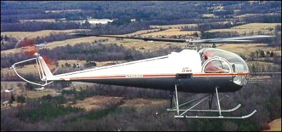
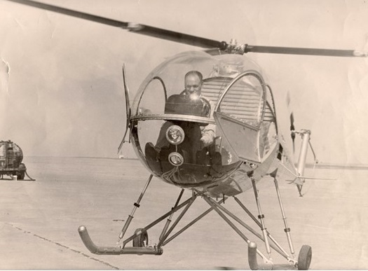
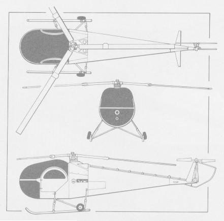
A relatively simple design, with blown main transparency and constant-taper fuselage. Double-articulated three-blade main rotor with pitch-change and flapping hinges close to hub and flap/lag hinges at 40% blade span; symmetrical, rigid, inboard blade section with 29% thickness/chord ratio, outboard section NACA 0012; outer blades quickly removable for compact storage; rotor brake standard; two-blade tail rotor mounted on starboard side, with guard. Transmission through automatic centrifugal clutch and planetary reduction gear. Bevel gear take-off from main transmission, with flexible coupling to tail rotor drive-shaft. Main rotor/engine rpm ratio 1:6.158; tail rotor ratio 1:1. Main rotor minimum speed 400 rpm; maximum 472 rpm. Conventional and manual controls; small fixed tailplanes on port and starboard sides of tailcone. A semi-monocoque fuselage with alloy-stressed skin. Inboard rotor blades have stainless steel leading-edge spar; outboard blades have extruded aluminium spar; polyurethane core with bonded aluminium envelope riveted to spar. All-metal tail rotor blades. Fixed skid type landing gear with oleo-pneumatic shock-absorbers; small retractable ground handling wheels, size 10×3.5, pressure 4.12 bar; fixed tailskid. Optional inflatable pontoons attach to standard skids for over-water operation. One 134kW Textron Lycoming IVO-360-A1A flat-four air-cooled piston engine, mounted vertically. Fuel contained in two interconnected bladder tanks behind cabin, total capacity 117 litres of which 115 litres are usable. Oil capacity 6.9 litres. Two seats, side by side in enclosed cabin; forward-hinged door on each side. Dual controls and cabin heater standard. Ground accessible baggage compartment, maximum capacity 22.7kg in forward end of tailcone.
In 1959 the Army procured five examples of the Brantly Model B-2 light helicopter for evaluation in the observation role. The five machines obtained by the Army (serials 58-1492 through -1496) were designated YHO-3 and tested at both Fort Rucker and the Naval Air Test Center at Patuxant River, Maryland. The aircraft was ultimately judged to be too small to be of practical military use and all five examples were eventually returned to the manufacturer.
Brantly B-2B
B-2 Engine: Lycoming 135 hp Rotors: 3-blade main 2-blade tail Rotor diameter: 23 ft Loaded weight: 1,250 lb Seats: 2
B2B Engines: Lycoming IVO-360-A1A, 180 hp,134kW. Main rotor diameter: 7.24m Fuselage length: 6.63m Height: 2.06m Disc loading: 3.7 lb/sq.ft. Pwr loading: 9.3 lb/hp. Max TO wt: 1670 lb / 757kg Empty wt: 1032 lb / 463kg Equipped useful load: 576 lb. Payload max fuel: 390 lb. Range max fuel/ cruise: 152 nm/1.8 hr. Range max fuel / range: 196 nm/ 2.3 hr. Service ceiling: 12,500 ft / 3290m Max speed: 161km/h Max cruise: 87 kt / 145km/h Max range cruise: 87 kt. ROC: 1400 fpm. HIGE: 4300 ft. HOGE: 2500 ft. Max sling load: 400 lb. Fuel cap: 186 lb. Seats: 2.
2 H2/YHO 3BR Engine: Lycoming IVO-360-A1A, 180 hp. TBO: 900 hrs. Main rotor: 23.7 ft. Length: 28 ft. Height: 6.8 ft. Max ramp weight: 1670 lbs. Max takeoff weight: 1670 lbs. Standard empty weight: 1069 lbs. Max useful load: 601 lbs. Zero fuel weight: 1490 lbs. Max landing weight: 1670 lbs. Max sling load: 400 lbs. Disc loading: 3.7 lbs/sq.ft. Power loading: 9.3 lbs/hp. Max usable fuel: 183 lbs. Max rate of climb: 1330 fpm. Service ceiling: 12,500 ft. Hover in ground effect: 4,300 ft. Hover out of ground effect: 2500 ft. Max speed: 87 kts. Normal cruise @ 3000 ft: 78 kts. Fuel flow @ normal cruise: 72 pph. Endurance @ normal cruise: 2.4 hr. Seats: 2.
Brantly B-2B Engine: Lycoming IVO-360, 180 hp Rotor span: 7.24 m Blade area: 0.203 sq.m MAUW: 757 kg Empty weight: 463 kg Max speed: 161 kph Cruise speed: 145 kph Climb rate: 9.6 m/s Seats: 2
Michael Bowlus used the tail of an HP-18 and the wings of an HP-11, reduced to 15 m., to develop his BZ-1, which first flew in 1984. This has an adapted North American F-86 Sabre drop tank for the front end of the fuselage, interconnected flaps and ailerons (the former extending to 90 degrees for approach control) and increased empty and gross weight of 249 kg/ 550 lb and 364 kg/ 780 lb respectively.
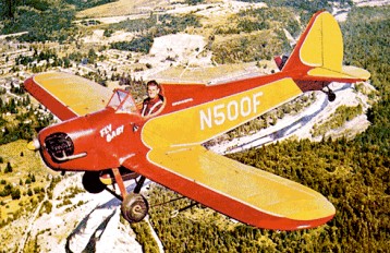
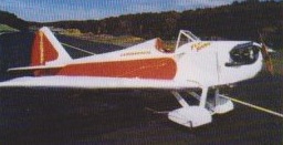
Originally designed in 1960 by former Boeing engineer Peter Bowers to compete in the first EAA design competition, the Fly Baby is a single-seat, open cockpit, folding-wing monoplane powered by engines ranging from 65 to 100 hp. It is built primarily of wood, with fabric covering. It’s got a big cockpit as Peter Bowers is six feet two inches tall. First flown in 1960 the Fly Baby 1-A single place monoplane won the 1962 EAA competition for the best amateur plane with a C-85 engine. The Fly Baby has the distinction of being one of the most enduring designs in the homebuilt field. It has been tested with floats and in 1968 was fitted with biplane wings which were interchangeable with the single wings. The wings are a wooden structure covered with Dacron fabric, and the fuselage is a conventional plywood-covered wooden structure with a single open-cockpit seat. Plans were made available to amateur constructors.
Most are powered by Continental A-65, C-75, C-85, or O-200 engines. The 100 hp Continental is recommended over the 85 hp engine as it is only 13 pounds heavier, and gives a cruise speed of 92 knots with a two-blade fixed-pitch propeller. The fully aerobatic aircraft has a 22 foot wingspan and is 19 feet long. It will climb at 700 fpm and weighs 651 lbs empty with a MAUW of 972 lbs.
The prototype Fly Baby 1 B biplane, which first flew in 1969, could be converted from mono¬plane to biplane in around an hour. The two monoplane wing panels are replaced by four smaller ones, plus a center section for the top wing. The biplane wings take longer to build, since there are four panels and a center section, and they’re swept rather than straight. And there are some internal braces and external tangs that have to be added to the fuselage. This can be done after the fuselage is done (The prototype was converted after completion), but it is easier during construction. The biplane is slower, and the wings don’t fold.
In monoplane or biplane configuration, the Fly Baby does meet the US rules for Sport Pilot. In the United States, you do not need an FAA medical to fly a Fly Baby.
This plane is a structurally simple and easy-to-fly airplane designed to the requirements of the Experimental aircraft Association for home construction and storage in a space 7 x 8 x 20 feet, which is equivalent to the standard home garage. Great emphasis has been placed upon safe flight characteristics and good low speed performance for takeoff and landing at some sacrifice of high speed. The structure has been designed for standard airplane engines from 65 to 85 horsepower and the aerodynamic features are of sizes and proportions suited to obtaining the best all-around performance in this power range. Because of this, there is not enough advantage to be gained from using engines of significantly higher power to offset the cost and weight penalties. Increasing the power to increase the aerobatic capability is not recommended. Fly Baby will do simple recreational aerobatics very well but is not intended for rough air show or competition maneuvers.
Bowers recommends Continentals between 65 and 85 horsepower. The Fly Baby isn’t a fast airplane so bigger engines don’t really give much. A reported Fly Baby which replaced the A-65 with a C-85, increased the cruise from 80 to 95 mph and his rate of climb from 500 to 1000 fpm.