1998:
F-47310 Roquefort
France
Offered Mignet Flying Flea
1998:
F-47310 Roquefort
France
Offered Mignet Flying Flea
Grumman American was established in 1972 when the Grumman Corporation acquired 80% of American Aviation’s stock in January 1973, and produced the Gulfstream 2 executive transport and the Lynx, Cheetah, Tiger, Cougar, and T-cat family of light aircraft. Also marketed the Super AgCat cropduster, built for Grumman by Schweizer Aircraft.
In 1976 Grumman Aviation moved production south to Savanna, Georgia.
During 1978 Grummans interest was bought out by American Jet Industries to form Gulfstream American Corp who continued production until late 1979, by which time 4879 aircraft had been produced: 1822 AA-1 series, 3054 AA-5 series and 3 prototypes.
Defense giant General Dynamics bought the business jet maker Gulfstream Aerospace in a stock deal estimated to be worth about $5.3 billion in 1999.
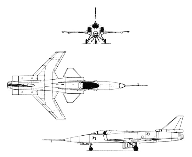
Grumman Aerospace, Rockwell International and General Dynamics, proposed to DARPA that a for-ward swept wing demonstrator should be built. The demonstrator would be used to: verify that composites could provide the wing stiffness required without severe weight penalties; verify the aerodynamic advantages of a forward swept wing indicated in wind tunnel testing; and expand the forward swept wing technology base.
DARPA responded favourably and there followed three years of intensive competitive design studies, culminating in Grumman Aerospace being selected to build two demonstrators in 1981 under an $80 million contract, based on their Project Design G 712. This was officially designated X 29A by the U.S. Air Force in mid 1981.
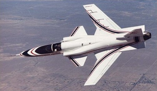
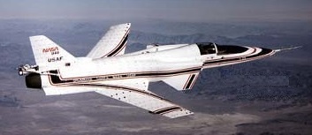
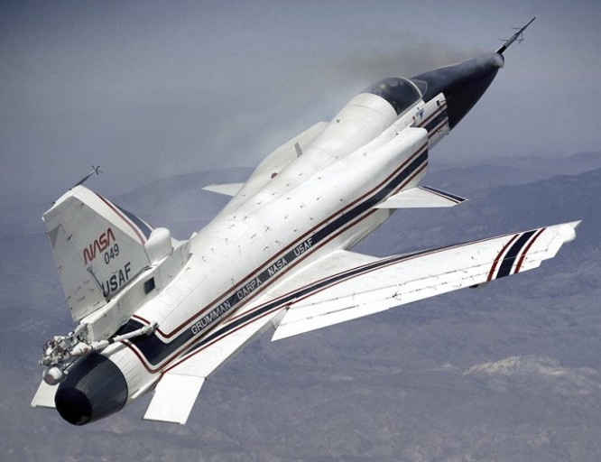
The X-29A was a single-seat jet aircraft fitted with a wing mounted at the rear of the fuselage, swept forward at 35 degrees, and having shoulder-mounted canards just behind the cockpit.
To save development time and money, Grumman used as many parts as practical from existing aircraft. The forward fuselage and nose landing gear are from a Northrop F 5A (the 15th built from the mid-1960s), and the main landing gear and control surface actuators are from a General Dynamics F 16A. Off the–shelf equipment includes the emergency power unit and the flight control servo actuators, also from an F 16A. The aircraft is powered by a single General Electric F404 after burning turbofan, developing 16,000 lb. thrust, and is the engine type used in the McDonnell Douglas F/A 18 Hornet.
The tapered variable incidence foreplane was selected after intensive wind tunnel testing and is used to provide pitch trim and control movements, as this type of surface provides lift for trim. It also acts as a slat to help the heavily loaded inboard section of the wing.
The X 29A is a highly unstable aircraft, the c.g. being no less than 35% aft of the aerodynamic centre of the wing/canard surfaces. Initially the planned instability was intended to be only 20%, and accordingly the canard had an area equal to 15% of the wing. Wind tunnel tests, however, showed that this would not give the degree of control required during transonic manoeuvres, and the canard size was increased to 20% of the wing, giving the current degree of instability.
The heart of the X 29A is its distinctive forward swept wing. It is a very thin wing; the thickness to-chord ratio being less than 5%. The wing area is 188 sq. ft. and the angle of forward sweep 30 deg.
Ultimately, the X-29 emerged with three digital channels so that any two could detect a failure in a third, plus a fourth, analogue backup channel which could control the aircraft over a limited flight envelope. The main role of the fourth channel was to protect the aircraft in case some unsuspected freak software mode disabled all three digital channels simultaneously.

The inboard end of the leading edge is swept aft, to alleviate some of the root stall problems associated with forward sweep. To preserve the structural integrity of the vital lower wing skin, the main landing gear retracts forward, into the fuselage ahead of the wing. The trailing edge of each wing root extends aft to form a large body strake ending in a controllable flap. The strakes add area behind the c.g. and hence improve directional stability.
It is on the outer, forward swept portion of the wing that the unique directional properties of carbon fibre laminates construction are used to overcome the adverse wing twist, or “divergence”, without the prohibitive weight penalty of a conventional aluminium alloy structure. A total of 752 plies is used, with 156 layers at the thickest section of the skin. To resist the natural tendency of the forward swept wing to twist, the layers are “rotated” some 10 deg. forward of the wing’s structural axis.
The laminated wing skins, at an angle to the bending axis, shear forward under compression and back¬ward under tension. The effect of shearing under load on the wing torsion box is to generate a nose down torque which counters the natural tendency of the wing to twist leading edge up. The carbon fibre skins are attached to a sub structure of conventional aluminium alloy construction, the front spar being of electron-beam welded titanium to cater for the high loads on the front part of the wing due to the forward sweep.
Full span “variable camber” flaperons are fitted to the wing trailing edge, these being used symmetrically for pitch control and asymmetrically for roll. The flaperons are in three sections, being hinged at two chord wise locations, so that they may be used to change the camber of the wing. The primary hinge is at 75% chord and the secondary hinge is at 90% of the chord. The flap sections are geared so that for every 1 deg. of flap deflection the aft section deflects an additional 1 deg. The flap increases manoeuvrability and reduces drag across the entire speed range. Programmed by the flight control computer, the flap alters the wing shape in flight as a function of changing conditions. The result is a constantly optimum wing shape.
The core of the wing structure is an electron-beam-welded box of titanium and light alloy, providing an exceptionally sturdy but generally conventional basis for the outer aerodynamic surfaces. The latter are single-piece upper and lower skins made of carbon fibre reinforced plastics up to 156 layers thick at the inboard ends. The skins are exceptionally light yet rigid, and can sustain violent manoeuvres without any possibility of aeroelastic divergence. The leading edges are fixed, with no provision for high-lift devices of any kind, but the trailing edges are fitted with full-span flaperons that can be used as camber-changing sections.
Located aft of the wing are the conventional rudder, plus a pair of strake flaps fitted at the extreme rear of the extended wing root trailing edges, nearly in line with the rudder. Powerful canard foreplanes with one-fifth of the wings’ area are located on the sides of the lateral inlets, and just forward of the inboard sections of the wing leading edge, which are conventionally swept back. The canards are driven through a triple-redundant fly-by-wire flight-control system, and are the aeroplane’s primary control surfaces in the pitching plane. The canards are used to trim out any tail up pitching moment by generating lift, augmenting the lift of the wing.
Flight tests have confirmed wind-tunnel predictions about the X-29’s flight characteristics: even at extreme high angles of attack the aircraft cannot be stalled and it retains full roll authority down to very low speeds. Early flight trials also indicated that fuel burn was lower than expected, an indication of extremely low drag.
The X 29A flew for the first time on 14th December 1984, from NASA’s Dryden Flight Research Facility at Edwards Air Force Base, California, with Grumman chief test pilot Chuck Sewell at the controls. For this first flight, which lasted 57 minutes, the landing gear and the variable camber trailing edge devices were kept down. The gear and flaps were retracted during the second flight on 4th February 1985. Two further flights were made on 25th February and 1st March. Two 360 deg. rolls were made during the third flight. After just these four flights the demonstrator was turned over to NASA in March 1985 for further flight testing.
In the initial phase of testing low altitude, high speed manoeuvres, the X 29 demonstrated high g turns tighter than anything achieved by a conventional fighter and displayed awesome potential for combat aircraft. For an extended test phase, the second aircraft was fitted with a vortex flow control system to test the possibility of using high pressure nitrogen injected directly into the vortices coming off the nose to help maintain control at high AoA. With this, pilots were able to achieve good control response to an AoA of 67 degrees.
The first aircraft (83-0003) flew on 14 December 1984, piloted by Charles Sewell, but was grounded on 6 December 1988 after its 242nd flight. The second X-29A (83-0049), flown for the first time on 23 May 1989, completed its flight test programme in October 1991. Between them the two aircraft completed 374 flights (more than any other X-craft) and demonstrated angles of attack up to 67 degrees (the target was 80). They also flew at Mach numbers up to 1.52 and reached altitudes up to 12200m. Both aircraft were now in store at the Ames-Dryden Flight Research Facility of NASA at Edwards AFB, California.
The X 29 tests ended in 1992 after 436 flights.
X 29A
Engine: 1 x General Electric F404 GE 400 after burning turbofan, 69847 N / 16,000 lb. s.t.
Wing span: 27 ft. 2.5 in. / 8.3 m
Length: 16.4 m / 53 ft 10 in
Height: 14 ft. 3.5 in. / 4.4 m
Wing area: 17.5 sq.m / 188.37 sq ft
Foreplane area: 35.96 sq.ft.
Empty wt: 13,800 lb. / 6260.0 kg
MTOW: 17,800 lb. / 8074.0 kg
Max. payload weight : 12819.9 lb / 5814.0 kg
Max speed: Mach 1.6 approx.
Ceiling: 15300 m / 50200 ft
Crew: 1
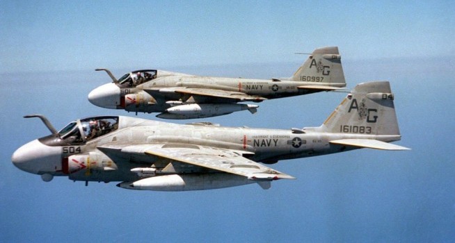
Tasked with finding and attacking targets under night or all weather conditions for the U.S. Navy/Marine Corps, A2F-1 Intruders were designed and developed by the Grumman Aerospace Corporation. The first trials aircraft flew on 19 April 1960 and eight YA2F-1 Intruder prototypes were delivered to the US Navy for evaluation, with original tilt able tailpipes and powered by two Pratt & Whitney J52-P-6 engines of 8500 lb.
The A2F-1 was designed to deliver nuclear or conventional weapons with great accuracy on targets that are completely obscured by bad weather or darkness. A digital integrated attack navigation system enables the pilot to set course for the target and then leave the aeroplane to fly itself. Two TV-type screens enable him to “see” the ground and target whatever the conditions. At the target the aircraft is capable of dropping its weapons and turn for home automatically.
The slightly swept tail surfaces have a variable incidence tailplane. Lateral control is by inset spoilers forward of the trailing edge flaps which extend over almost the full wing span. Full span leading edge flaps are fitted. The outer wings fold upward and inward for ship-board stowage. Sideways opening air-brakes are on each side of the rear fuselage. The tricycle undercarriage has twin nose-wheels and a single wheel on each main unit. The nosewheel retracts rearward and main units forward.
The first prototype flew in November 1960.

The first US Navy attack squadron to receive the Grumman A 6A Intruder, VA 42, re-equipped with the type at Oceana NAS, Virginia, in 1963.
In August 1964 it was reported that South Africa, rebuffed by the US State Department in bid to buy Grumman Intruders because of its race policies, was buying British Buccaneers instead.
From the A 6A was evolved the initial EA 6A ECM version for the Navy, its potential such that an advanced ECM version was developed in late 1966.
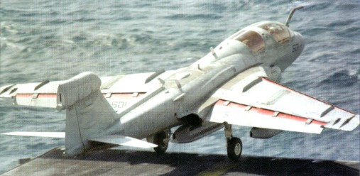
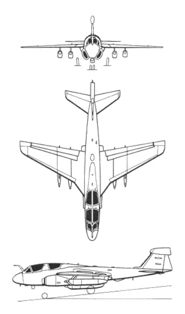
A development contract was issued in autumn 1966 and the EA-6B Prowler is externally similar to basic A-6 except longer nose enclosing four-seat cockpit and large pod on fin. First flown on 25 May 1968, delivery of first 12 production aircraft started January 1971. The first flew with an ALQ-99 jamming system which has evolved from being able to cope only with individual emitters (EXCAP), through several emitters (ICAP), to groups of weapons systems such as an air defence complex (ICAP¬ 2). The last of 170 was delivered on 29 July 1991.
The Grumman EA 6B was the Navy’s first aircraft to be purpose designed and built for tactical electronic warfare, two of the crew being ECM officers to operate the airborne equipment which can detect, identify, locate, and jam the emissions of hostile radars.
Eight Prowlers were deliv¬ered to the US Navy in 1986, and plans call for production of the current ICAP-2 (Improved Capability) EA-6B shipborne electronic warfare aircraft to continue until at least 1991. Earlier EA-6Bs are being upgraded to ICAP-2 standard, which includes power management, improved emitter identification and correlation, and better reliability and maintainability. The first ICAP-2 flew in June 1980. EA-6Bs can now carry Harm anti-radiation missiles.
The A-6E began to enter service in 1972.
On 22 March 1974 Grumman flew the first A-6E TRAM version of the Intruder, this incorporating a turreted electro-optical sensor package for the delivery of laser-guided weapons; the TRAM target recognition attack multi-sensor) added infra-red and laser equipment to the full A-6 avionics systems.
Grumman A-6/TRAM Intruder Article
An advanced version of the Intruder subsonic all-weather carrier-borne strike aircraft, the A-6F, was scheduled to fly during 1987. Production deliveries will begin in 1989, against US Navy/USMC requirements for 150 aircraft. A-6F improvements include a new Norden high-resolution synthetic-aperture radar, stand-off ASM, and AIM-120 Amraam/ AIM-9 Sidewinder AAM capability. The A-6F will be powered by two 40.07kN General Electric unreheated F404 turbofans, will have a new wing designed by the Boeing Military Airplane Company, and will be fitted with a new CRT¬ based cockpit and digital avionics. Much of the avionics being carried in five external pods.
The new Boeing wing, which is to be retro-fitted to all existing A-6E/KA-6Ds from 1987, will offer an 8,000hr service life. A-6E target recognition and attack multisensor (Tram) production continues, and 12 were delivered in 1986. The modification of earlier A-6Es to accept Tram turrets also progresses. The tram turret houses both a Flir system and a laser tracker/designator.
The KA-6D is a flight-refuelling tanker converted from the original A-6A Intruders or from older A-6Es.
On 3 April 1989 an A-6E made its first test flight fitted with Boeing-built composite wings.
A total of 482 A 6 were built.
Northrop Grumman undertook EA-6B Prowler remanufacturing,
The US Navy continued to fund the A-6F in 1988 although production was no longer planned. Two A-6Fs were flying, the third, intended as a test-bed for the digital avionics suite, entered testing in late August 1988.
A2F-1
Engines: 2 x Pratt Pratt & Whitney J52-P-6, 8500 lb
Wingspan: 53 ft
Length: 53 ft 5 in
Height: 15 ft 1.75 in
Empty weight: 24,000 lb
MTOW: 54,000 lb
Max speed: 720 mph at SL
Max cruise: 685 mph at SL
Hardpoints: 4 wing, 1 fuselage
A-6
Engines: 2 x Pratt & Whitney J-52-P-8A, 41.3kN
Weight empty : 26008.0 lb / 11795.0 kg
Max take-off weight: 27500 kg / 60627 lb
Wingspan: 16.2 m / 53 ft 2 in
Length: 16.3 m / 53 ft 6 in
Height: 15.584 ft / 4.750 m
Wing area: 49.2 sq.m / 529.58 sq ft
Wing loading: 114.39 lb/sq.ft / 558.00 kg/sq.m
Max. speed: 1000 km/h / 621 mph
Cruise speed: 770 km/h / 478 mph
Ceiling: 12700 m / 41650 ft
Range w/max.fuel; 5000 km / 3107 miles
Crew: 2
Armament : 6804kg ext. (5 pt.)
EA-6A Prowler
KA-6D Intruder
A-6E Intruder
Engine: 2 x P&W J52 P 8A, 9,300lb turbojet.
Installed thrust (dry): 83 kN.
Span: 16.2 m.
Length: 16.7 m.
Wing area: 49.1 sq.m.
Empty wt: 12,000 kg.
MTOW: 26,580 kg.
Warload: 8165 kg.
Max speed: 1040 kph.
Initial ROC: 2300 m / min.
Ceiling: 12,950 m.
Fuel internal: 9030 lt.
Max range: 4399 km.
Air refuel: Yes.
Combat radius hi-lo-hi: 1415 km.
A-6F Intruder
EA-6B Prowler
Engine: 2 x P&W J52-P-408 turbojet, 11,200 lb thrust.
Installed thrust: 99.6 kN.
Span: 16.2 m / 53 ft 2 in
Length: 18.2 m
Wing area: 49.1 sq.m / 528.51 sq ft
Height: 5.0 m / 16 ft 5 in
Empty wt: 15686 kg / 34582 lb
MTOW: 26535-28655 kg / 58500 – 63174 lb
Max speed: 965 km/h / 600 mph
Cruise speed: 850 km/h / 528 mph
Initial ROC: 2540 m / min.
Ceiling: 11,600 m / 38050 ft
T/O run: 815 m.
Ldg run: 655 m.
Fuel internal: 8870 lt.
Range: 535 km.
Endurance: 1 hr loiter.
Range w/max.fuel: 4000 km / 2486 miles
Crew: 4
A2F-1
Engines: 2 x Pratt & Whitney J52-P-6, 8500 lb

As an ensign in the Navy, Leroy Randle Grumman had worked with Albert and Grover Loening on a Navy monoplane contract. Upon resigning his naval commission in 1920, Grumman joined the Loenings as test pilot for their Air Yacht amphibians, and over the next several years, he took over full responsibility for the company’s aircraft design.
The Loenings sold out their company in 1929 and backed Grumman in a venture of his own incorporated in 1929 at Farmingdale, New York. With their investment of $30,000 making up almost half of the initial capital, Grumman and five other engineers opened the Grumman Aircraft Engineering Corporation in an abandoned garage in Baldwin, Long Island.
Contractor to U.S. Navy and Coast Guard. Built FF-1 (first flown 1931) and SF-1 two-seat biplane fighters with retractable landing gear, followed by single-seat F2F (first flown October 1933) and F3F (delivered 1936), plus all-metal amphibian as the JF-1 (first flown May 1933), later known as the Duck.
In 1936 Grumman moved to Bethpage, Long Island, NY.
Subsequent production, mainly for the U.S. Navy and Marine Corps, included F4F Wildcat fighter (first Grumman monoplane, first flown September 1937), TBM Avenger torpedo-bomber (first flown August 1941), F6F Hellcat fighter (delivered from 1943), F7F Tigercat twin-engined carrier fighter-bomber (first flown December 1943) and F8F Bearcat fighter (first flown August 1944) during Second World War, plus Widgeon and Goose (delivered from 1939) amphibians.
By 1943 his staff had grown from six to 25,000 employees.
Postwar aircraft included the antisubmarine Guardian (first flown December 1945), Albatross amphibian (first flown October 1947), F9F Panther as its first jet fighter (first flown November 1947), and F11F Tiger day jet fighter (first flown July 1954 in original F9F-9 form).
Grumman’s entry into specialized electronic warfare aircraft began in December 1952 with the first flight of its S2F Tracker (later S-2), though this was a carrierborne antisubmarine aircraft. From Tracker were developed variants for carrier transport operations; the C-1 Trader and, more importantly, the WF (later E-1) for airborne early-warning, with an over-fuselage radome (first flown March 1957) and based on the S-2A. Such was the success of the E-1 concept that the much improved E-2 Hawkeye was developed, which first flew in October 1960 (originally as W2F-1) and remains in production in 1999 by Northrop Grumman, itself leading to the C-2 Greyhound transport derivative (first flown November 1964). Grumman also developed the OV-1 Mohawk for the U.S. Army for observation, first flown April 1959 and also using the successful twin-turboprop engine layout.
In April 1960 Grumman flew the A2F-1, which in production form became the A-6 Intruder twin-jet carrier borne long-range and low-level strike aircraft, finally withdrawn from service in the late 1990s. Intruder itself spawned an electronic warfare variant, the EA-6 Prowler, first flown May 1968 and still in service in 1999. The final fighter to carry the Grumman name was the F-14 Tomcat, designed as a carrier based variable-geometry long-range type armed with super-long-range Phoenix air-to-air missiles (first flown December 1970, entering service with the U.S. Navy from 1972 and exported to Iran for land-based operations from 1976).
Grumman merged with American Aviation to form Grumman American.
By the time Tomcat had flown company had been divided (1969) into Grumman Aerospace and other individual corporations via the Grumman Corporation holding company. American Aviation Corporation became part of Grumman American Aviation Corporation in 1973. In May 1994 Grumman and Northrop merged to form Northrop Grumman.
The prototype Genesis 1 flew for the first time in 1993, and various improvements were applied, resulting in the production version, Genesis 2. The later has slightly modified wing geometry, fully retractable landing gear and a ballistic parachute (optional).
The design provides for automatic control hookups, and a ballistic recovery parachute is intended to be fitted as standard. Kits and complete airframes are to be produced by Sportina Aviacija in Lithuania, the builder of the LAK-12. The production version, Genesis 2, is expected to bring empty weight back to close to that predicted for the prototype. Other refinements incorporated as a result of prototype flight testing include a change to the aerodynamic twist to the wing, a modified tip airfoil section and a retractable nose wheel.
The kit price in 1997 was US$27,900.
Wing span: 15.0 m
Length: 4.86 m
Wing Area: 11.15 sq.m
Airfoil: Roncz
Aspect ratio: 20.2
Empty weight: 241 kg
Max. weight: 526 kg
Minimum speed: 67 km/h
Maximum speed: 276 km/h
Stall: 42 mph
Best glide ratio: 44:1 at 97 km/h
Minimum sink rate: 0.58 m/s
Seats: 1
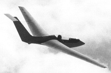
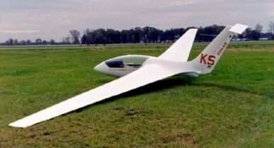
The Genesis I is a standard class glider from Marion, Ohio-based Group Genesis and intended for the homebuilt market.
Chief designer Jim Marske was given a clean sheet and chose a flying wing concept, but with conventional pilot pod and tall vertical stabiliser, topped by a small elevator, not tailplane. Aerodynamicist John Roncz, whose previous work has included the world-circling Voyager, did extensive work with computer modelling to come up with the final shape. The wing is a stable aerofoil with several changes in section and forward sweep across the span, and initial pilot reports (four different pilots flew the prototype within its first dozen flights) indicate high stability and control coordination.
The small horizontal surface found at the top of the Genesis’ fin is used only to control the glider’s angle of incidence. The wing has reverse sweep in order to put the variable masses close to the center of gravity, and incorporates water ballast tanks.
The prototype flew for the first time in 1993, and various improvements were applied, resulting in the production version, Genesis 2.
Specifications are for the prototype Genesis 1 as designed : on completion, empty weight was substantially greater.
Wing span: 15m / 49.2ft
Wing area: 11.19sq.m / 120.5sq.ft
Empty Weight: 227kg / 500lb
Payload: 298kg / 657lb
Gross Weight: 525kg / 1157lb
Wing Load: 46.91kg/sq.m / 9.6lb/sq.ft
Water Ballast: 0
Aspect ratio: 20.2
Speed max: 180 mph.
Cruise: 140 mph.
Stall: 40 mph.
L/DMax: 43 120 kph / 65 kt / 75 mph
MinSink: 0.71 m/s / 53 kt / 61 mph
Airfoil: Roncz G-74S
Structure: GFRP/CFRP/aramid
Seats: 1
Landing gear: single wheel.
Genesis Group is a team assembled around Jim Marske, Robert Mudd and John Roncz (famous aerodynamicist who collaborated with Burt Rutan, the much renowned designer of “canard” airplanes), and led by Jerry Mercer. The goal of this group was to develop a Standard class high-performance glider, made of composite materials, with a self-stable wing, utilising the latest design and aeronautical construction technology.
1995-2008: 1530 Pole Lane Rd., Marion, OH 43302, USA.
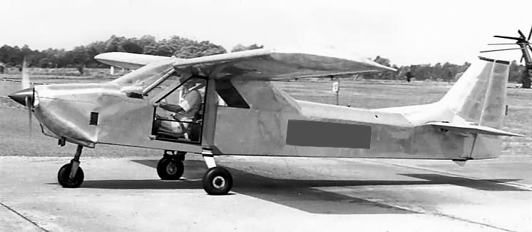
An original one-of-a-kind homebuilt aircraft, designed and built by James Bredelet and Louis Gros for two to four persons. The aircraft had a cantilever wing and was powered by one 130 hp Continental IO-240-A engine. It first flew on September 4, 1982.
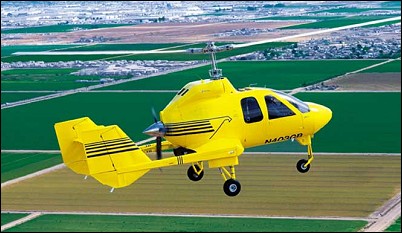
Design changes to H2X and later Hawk III in October 1998 resulted in Hawk 4. Initial aircraft (N402GB) first flew 29 September 1999, powered by a Continental piston engine, and made first vertical take-off on 9 December 1999; had flown 120 hours in 200 sorties by early April 2000. In September 2000 company switched certification effort to turbine-powered Hawk 4T (N403GB), which was renamed Hawk 4 at this time following abandonment of piston-engined version; the following October Groen changed its focus to seek government contracts for Hawk 4, slowing certification process for both piston- and turbine-powered versions until it sees market upturn.
GBA analysises and optimises gyroplane rotor blade airfoil performance resulting in a family of natural laminar-flow airfoils for the rotor blades of the Hawk 4 and successor gyroplanes. The airfoil design optimizes the lift/drag relationship for the Hawk rotor system. Initial Hawk models will use aluminum rotor blades with GBA’s proprietary airfoil design, and subsequent models are anticipated to use composite blades with an enhanced GBA proprietary airfoil design that will permit increased operating speeds.
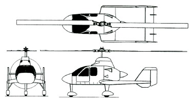
The aircraft features twin tailbooms supported by stub-wings which also house main landing gear, and twin stabilisers and rudders with fixed horizontal tail surface mounted between the vertical tails. A two-blade, semi-rigid aluminium teetering rotor with swashplate has a rotor speed of 270rpm. The collective pitch-controlled rotor head allows vertical take-off (zero ground roll) and enhanced flight performance. Rotor brake is standard. Actuation by pushrods. Patented dual-control stack cyclic flight controls.
The structure had a steel mast and engine mounts; stressed skin aluminium semi-monocoque fuselage, tail unit, hub structure and propeller; composites nose, engine cowling and wingtips; acrylic windscreen and doors; glass fibre nosecone and engine cowling.
The undercarriage is fixed tricycle type with mainwheel tyres 6.00×6; nosewheel 5.00×5, Cleveland hydraulic brakes, and twin safety wheels at rear of tailbooms.
Hawk 4 piston-powered version has air-cooled, six-cylinder Teledyne Continental TSIO-550 rated at 261kW at 2.700rpm; prototype had four-blade MTV propeller but production models will have Hartzell three-blade constant-speed propeller. Engine provides power to rotor for prerotation to provide for short and vertical take-off capability; power to rotor system never engaged during flight.
Fuel capacity is 284 litres in a single tank at the rear of the fuselage and a refuelling point at the top of the fuselage. Oil capacity 11.4 litres.
The pilot and up to three passengers are in an enclosed cabin in two pairs of seats. The rear seats folding to provide baggage space.
The electrical system is 28V DC.
The production prototype for Hawk series was powered by a 134kW Textron Lycoming O-360-A4M flat-four.
The company has a flight test facility at Buckeye, Arizona, where, on 12 July 2000, the prototype Jet Hawk 4T / Hawk 4 made its initial flight. This turbine-engine version is powered by a Rolls-Royce Model 250 420shp turboprop engine driving a three-blade constant-speed propeller, first flown (N403GB) on 12 July 2000. Other changes include addition of underfins and taller landing gear. Two further prototypes under construction.
The Hawk 4T is sold fully assembled with a Rolls-Royce Model 250 B17C gas turbine for $749,000 in 2001. By May 2003, deposits on 148 aircraft had been taken, via 12 dealerships at around US$749.000 (2003). Fractional ownership programme announced July 2001 but later dropped.
The Hawk 4 was an integral part of security during the 2002 Winter Olympic and Paralympic Games. On 28 December 2001, Groen announced contract with Utah Olympic Public Safety Command for lease of Hawk 4, beginning 20 January 2002, for security patrols at Salt Lake International Airport, equipped with video downlink system, Spectrolab SX-5 searchlight and additional radios. The Hawk 4, during its operational period for the Utah Olympic Public Safety Command (UOPSC), was available 24-7, completed 67 missions and accumulated 75 hours of maintenance free flight time.
Hawk H4
Engine: Rolls-Royce 250, 420shp
Rotor diameter: 12.80m
Fuselage length: 7.31m
Overall height: 4.11m
Empty weight: 835kg
Max. take-off weight: 1587kg
Useful load: 960 lb
Fuel capacity: 75 USgal
Max. speed: 238km/h
Cruising speed at 75% power: 212km/h
Max. rate of climb at sea level: 457m/min
Service seiling: 4875m
Take-off run: 8m
Range with max fuel at 75% power: 584km