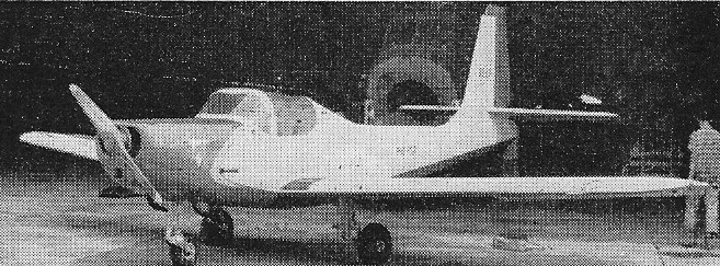
IST/PAF ARDA XL-17 Musang

The XL-17 ” Musang” (Wildcat) is the fourth aircraft in the series designed and constructed by the Institute of Science and Technology of Manila in the Philippine Republic, and is part of a programme to test the application of local materials, such as home-grown woods, to aircraft structure. During their experiments the Institute developed a material which it called “Wobex”. “Wobex” consists of diagonally woven strips of thin bamboo glued together, made air tight and leakproof, and finished on the surface with a layer of fine sawdust and glue. Its main use is as a stressed skin covering.

In the mid-1950s the Philippine Institute of Science and Technology (I.S.T.) designed the single engine, tricycle undercarriage, low wing monoplane L-17 was one of them.

Designed by Antonio J. de Leon, its wing was a single-piece wooden structure with 5° of dihedral and a straight-tapered plan. It was plywood-covered and had split flaps inboard of the ailerons. The cantilever tail unit was similarly constructed with the straight-tapered horizontal surfaces on top of the extreme aft fuselage; the single-piece elevator carried an offset trim tab. The vertical tail was tall and straight-edged; the bottom of the horn balanced rudder was above the elevator and just aft of its hinge, with a small cut-out to allow for elevator deflection.

Fuselage is a one-piece semi-monocoque structure with wooden bulkheads and stringers covered by a “Wobex ” skin, which in turn is covered with fabric for final finishing and polishing. Fuel tanks are fitted aft of the seats and the rest of the fuselage space can be used as either a radio compartment or as baggage space. The engine mount is the standard truss-type with attachments at four points to the firewall bulkhead, which is reinforced for the attachment of the nose landing gear. The cantilever wing is trapezoid in form and of one-piece construction that tapers in chord and length. It is made up of one main and one auxiliary spar of box-type construction and reinforced diagonal spar. The leading edge is covered with a thick plywood covering to take torsional and chordwise shear loads. Overall wing covering is fabric. Slotted type ailerons are fitted and simple split flaps are located under the wings between the ailerons and the fuselage. The wing root upper section upper covering is reinforced to serve as a step and walkway to the cockpit. A tricycle undercarriage is fitted, the main gear to the main wing spars and the nose gear to the firewall bulkhead.

Cockpit seating two side by side under a single piece canopy. A 108 hp (80 kW) Lycoming O-235-C1 flat-four engine drove a two-blade propeller. The fixed tricycle undercarriage had rearward-sloping oleo legs mounted to the wings, giving a track of 2.40 m (7 ft 10 in).

The first flight of the L-17 was scheduled for May 1956.

Engine: 1 × Lycoming O-235-C1, 81 kW (108 hp)
Propeller: 2-bladed , fixed pitch, wooden
Wingspan: 9.60 m (31 ft 6 in)
Wing area: 13.40 m2 (144.2 sq ft)
Airfoil: US 35B at root, NACA 23012 tip
Length: 7.20 m (23 ft 7 in)
Height: 3.20 m (10 ft 6 in)
Empty weight: 510 kg (1,124 lb)
Gross weight: 735 kg (1,620 lb)
Fuel capacity: 68 L (15 Imp gal, 18 US gal)
Maximum speed: 210 km/h (130 mph, 110 kn)
Cruise speed: 175 km/h (109 mph, 94 kn)
Stall: 80 kph
Rate of climb: 3.8 m/s (750 ft/min)
Crew: 2
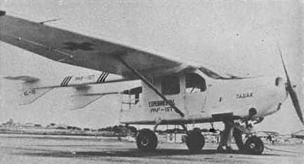
IST/PAF ARDA XL-15 Tagak

In the early 1950s in the Philippines, the Institute of Science and Technology (I.S.T., previously known as the Bureau of Science) designed at least three different prototypes, both to investigate the scope for local aircraft design and production and to examine the use of indigenous materials in their construction. One such material of interest was Wobex (Woven bamboo experimental), a reinforced woven bamboo.

The XL-15 Tagak was the second of these prototypes, developed in collaboration with the Philippine Air Force, it was designed by Antonio J. de Leon as a utility, liaison or ambulance aircraft and as a test bed for the use of local materials in aviation. It was a single-engine, high-wing monoplane with a twin-boom layout and tricycle undercarriage to enable easy access to the fuselage pod via rear doors. The inner wing sections, fitted with slotted flaps on the trailing edges had constant chord but further out the wings tapered, with slotted ailerons. There was a single lift strut on each side between wing and lower fuselage, with an airfoil profile to add to the lift from the wings.

The fuselage of the Tagak was a wood and plywood framed semi-monocoque skinned with Wobex and ply. Its cabin, behind the 185 hp Lycoming flat six engine, was 3.26 m (10 ft 6 in) long to the rear of the pod. There were two front seats under the wing leading edge, two more behind and room for one or two (stacked) stretcher cases. The cabin had two windows on each side and the rear part of the pod, which projected behind the wing trailing edge, was also extensively glazed. The two tail booms, of all ply construction, were integral with the wing centre section. The fins, with long chord underside fillets, were integral with the booms. The tailplane was rectangular and extended beyond the fins, carrying a horn balanced elevator. The fixed surfaces were of wood and ply construction, with Wobex covering; control surfaces were fabric covered.

Flight testing of the Tagak began in October 1954. By 1956 some small modifications had been made: rudder area was increased and a shimmy-damper added to the nosewheel leg.

Only one was built.

Engine: 1 × Lycoming O-425A, 138 kW (185 hp)
Propeller: 2-bladed fixed pitch
Wingspan: 12.0 m (39 ft 4 in)
Wing area: 20.30 m2 (218.5 sq ft)
Airfoil: NACA 23012 (inner section), USA 35B outer section
Length: 9.15 m (30 ft 0 in)
Height: 2.80 m (9 ft 2 in)
Empty weight: 780 kg (1,720 lb)
Gross weight: 1,250 kg (2,756 lb)
Fuel capacity: 174 L (38 Imp gal, 46 US gal)
Maximum speed: 200 km/h (120 mph, 110 kn)
Cruise speed: 158 km/h (98 mph, 85 kn)
Range: 675 km (419 mi, 364 nmi)
Service ceiling: 4,000 m (13,000 ft)
Rate of climb: 3.0 m/s (590 ft/min)
Seats: 4

IST/PAF ARDA XL-10B Balang / Grasshopper

The XL-10B Balang (Grasshopper) was a powered glider joint project of Institute of Science and Technology (IST) and Philippine Air Force (PAF) Air Research and Development Authority (ARDA).

It first flew in 1953.

Engine: 20 hp
Wingspan: 12 m
Length: 5.20 m
Height: 1.5 m
Aspect ratio: 8.1
Wing area: 17.8 sq,m
Empty weight: 185 kg
Loaded weight: 280 kg
Max speed: 125 kph
Cruise speed: 72-80 kph
Stall: 49 kph
Glide speed: 75 mph

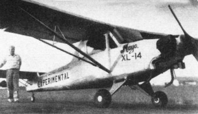
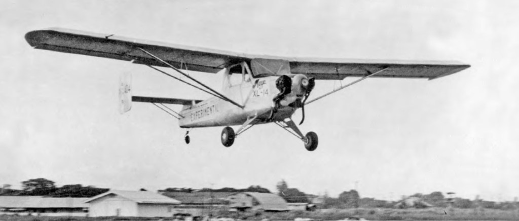
I.S.T.XL-14 Maya

In the early 1950s in the Republic of the Philippines, the Institute of Science and Technology (I.S.T., previously known as the Bureau of Science) designed at least three different prototypes, both to investigate the scope for local aircraft design and production and to examine the use of indigenous materials in their construction. One such material of interest was Wobex (Woven bamboo experimental), a reinforced woven bamboo.

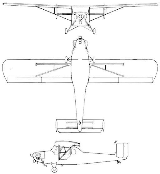
Designed by Antonio J. de Leon, the XL-14 Maya (until 1995 the Maya was the national bird of the Philippines) was the first of this series of prototypes. It was a single-engine, high-wing monoplane of standard layout except for its twin tail. The wing had constant chord and was built around two parallel, solid spars and wooden ribs. The leading edges were covered and reinforced with Wobex and the rest of the wing was fabric covered. The centre section was integral with the cabin top and the outer wings were braced on each side with V struts from the wing spars to the lower fuselage. Ailerons and slotted flaps were fitted. It had a strut braced tailplane, set slightly above the fuselage top on a short pylon. The tailplane carried almost rectangular endplate fins and rudders. The tail structure was wooden with fabric covering.

The Maya, bearing its experimental category registration PI-X-104 on its fins, had a semi-monocoque fuselage with wooden stringers and Wobex mat covering. The cabin stood above the rear fuselage line, enclosing side-by-side seats with a third, occasional seat, or luggage space, behind. In front a 75 kW (100 hp) Lycoming flat four engine, with cylinder-heads exposed, drove a two-blade propeller. It had a conventional undercarriage, with each mainwheel mounted on V-struts and half axles hinged to the fuselage central underside via rubber shock absorbers. The fixed tailwheel was steerable.

The date of the Maya’s first flight is not known, though the aircraft was complete by May 1955 and a later design, the XL-15 Tagak was being flight tested by October 1954. Only one Maya was built, for although it was described as being suitable for agricultural use and for utility and observation work, its function was always as a constructional material experimental aircraft.

Engine: 1 × Lycoming O-235-2, 75 kW (100 hp)
Propeller: 2-bladed wooden, fixed pitch
Wingspan: 10.24 m (33 ft 7 in)
Wing area: 16.0 sq,m (172 sq ft)
Length: 6.30 m (20 ft 8 in)
Height: 2.40 m (7 ft 10 in) tail up
Empty weight: 510 kg (1,124 lb)
Gross weight: 780 kg (1,720 lb)
Fuel capacity: 68 L (15 Imp gal, 18 US gal)
Maximum speed: 184 km/h (114 mph, 99 kn)
Cruise speed: 150 km/h (93 mph, 81 kn)
Range: 480 km (300 mi, 260 nmi)
Service ceiling: 3,820 m (12,530 ft)
Rate of climb: 3.6 m/s (710 ft/min) initial
Capacity: 2/3 (3rd passenger under 50kg (110 lb))

Isotta Fraschini V.5

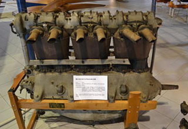
The Isotta Fraschini V.5 of 1916 was an Italian eight-cylinder, water-cooled, in-line piston aero engine first run in 1915. The “V” denoted “Volo” or “flight” rather than piston arrangement.

The V.5’s construction was fairly typical of aircraft engines of the period with cast-iron cylinders mounted in pairs with common heads and water jackets. It had much in common with the six-cylinder Isotta Fraschini V.4 and was built at a similar time. Though powerful, it was very heavy and thus, like some other Isotta Fraschini engines, better suited to airships than aircraft.

Applications:
Forlanini airship

Specifications:
Type: 8-cylinder inline
Bore: 130 mm (5.12 in)
Stroke: 180 mm (7.09 in)
Displacement: 19 L (1,165 cu in)
Length: 1,990 mm (78.3 in)
Width: 600 mm (23.6 in)
Height: 1,010 mm (39.8 in)
Dry weight: 351 kg (774 lb)
Valvetrain: Overhead camshaft
Fuel system: Twin carburettors, twin eight spark magnetos
Oil system: Forced feed
Cooling system: water; cast iron cylinders in pairs, each pair in a steel water jacket
Reduction gear: direct
Power output: 183 kW (245 hp) at 1,400 rpm

Isotta Fraschini V.4

The Isotta Fraschini V.4 of 1916 was an Italian six-cylinder, water-cooled, in-line piston aero engine of World War I (the “V” denoted “Volo” or “flight”). Its construction was fairly typical of aircraft engines of the period with six cast-iron cylinders mounted in pairs with common heads. This engine was also produced by Alfa Romeo.

Applications:
CANT 7
Caproni Ca.3
Caproni Ca.30
Caproni Ca.33
Caproni Ca.34
Caproni Ca.35
Caproni Ca.36
FBA Type H
Macchi L.1
Macchi M.5
SIAI S.8

Specifications:

V.4b
Type: Six-cylinder, water-cooled, in-line piston engine
Bore: 130 mm (5.12 in)
Stroke: 180 mm (7.09 in)
Displacement: 14.3 L (874 cu in)
Length: 1,470 mm (58 in)
Width: 460 mm (18.11 in)
Height: 1,020 mm (40.15 in)
Dry weight: 264 kg (584 lb)
Valvetrain: Overhead camshaft
Fuel system: Twin carburettors, two six spark magnetos
Oil system: Forced feed
Cooling system: Water; cylinders in pairs, each pair in a steel water jacket
Power output: 142 kW (190 hp) at 1,450 rpm
Compression ratio: 4.8

Isotta Fraschini Delta / R.C.21/60 / R.C.35

Isotta Fraschini Delta RC131

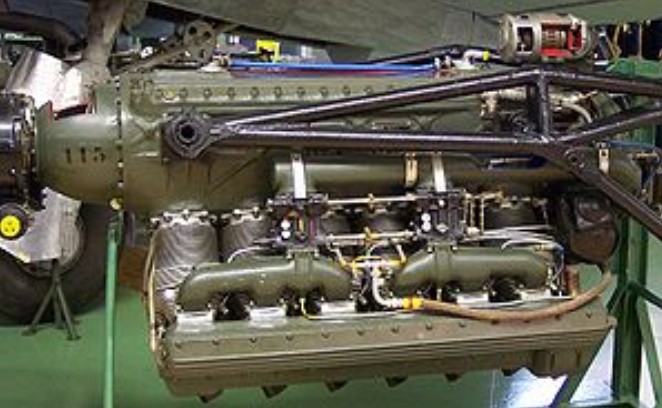
The Delta was a 12-cylinder inverted-V aircraft engine built by Isotta Fraschini prior to and during World War II. First run in 1927, the Delta produced about 750 hp in common versions, although others were rated up to 900 hp. The Delta was not widely used, although it could be found on a number of production aircraft and some advanced prototypes.

Although the air-cooling might be considered an anachronism even during the 1930s, the engine included a number of otherwise advanced features. For instance, the valves were powered by dual overhead cams driven by power shafts at the rear of the engine. Exhaust ports were arranged to exit toward the middle of the engine, one cylinder bank being the mirror of the other, allowing the piping to be ganged below the engine nacelle.

Around 3300 were built.

Applications:
Ambrosini SAI.107
Ambrosini SAI.207 prototype
Ambrosini SAI.403 prototype
CANT Z.515
Caproni Ca.313
Caproni Ca.314
Caproni Ca.331
Caudron C.714 (C.760) prototype
Henschel Hs 129 prototype
Reggiane Re.2001 prototype

Specifications:

Delta R.C.35 IS
Type: 12-cylinder air-cooled 60 degree inverted vee
Bore: 132 mm (5.197 in)
Stroke: 160/165 mm (6.299/6.496 in), with main and articulated rod
Displacement: 26.685 Litres (1,628.44 in³)
Length: 2000 mm (78.8 in.)
Width: 840 mm (33.07 in.)
Height: 883 mm (34.76 in.)
Dry weight: 510 kg (1,111 lb)
Valvetrain: 2 Poppet valves per cylinder, sodium cooled exhaust valves, double overhead camshafts.
Supercharger: single stage single speed centrifugal type supercharger, gear ratio 9.8:1
Fuel system: 4Isotta Fraschini downdraft carburetors Fuel type: 80/87 octane petrol (aviation gasoline) Oil system: dry sump, 2 scavenging, 1 pressure pump Cooling system: Air-cooled Power output: 770hp/2600rpm take off, 750hp/2600rpm/4000meters. Reduction gear ratio 0.64:1 Specific power: 0.75 hp/in³ (34.1 kW/L) Compression ratio: 6.4:1 Specific fuel consumption: 270 grams/hphour maximum, 250 grams/hp*hour cruise (70%)
Power-to-weight ratio: 1.485 hp/kg (0.67 hp/lb)

Isotta Fraschini Asso XI / XI R / XI R.C.40

Isotta Fraschini Asso XI

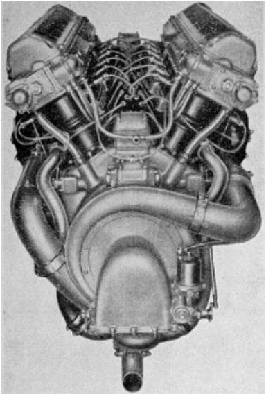
Isotta Fraschini produced a long series of engines with the name Asso (Ace, in English). The Asso XI.RC was an upright, liquid-cooled V-12 engine with maximum power output in the range 670-725 kW (900-970 hp) depending on the degree of supercharging. There were two variants, differing only in their supercharger speed: the R.C.40 ran at a little over 10 times the crankshaft speed and enabled the engine to maintain a rated power of 623 kW (836 hp) to an altitude of 4,000 m (13,120 ft) (hence the 40 in the variant name) whereas the R.2C.15 held 655 kW (880 hp) to 1,500 m (4,920 ft) with a supercharger gearing of 7.

All variants of the RC.40 had much in common constructionally with the earlier Asso-750.RC, though they had two, rather than three, banks of 6 cylinders and 4 rather than 2 valves per cylinder. Cylinder barrels were machined from carbon steel with flat-topped heads and valve seatings. Each barrel had a separate sheet steel water jacket. Cast aluminium head blocks were bolted to each of the two banks of 6 cylinders, providing valve ports, guides, coolant passages and camshaft supports. The pistons were also aluminium castings. The crankshaft was a 6-throw design with 8 plain bearings and a double row ball thrust bearing between the front two. The connecting rods had bronze bush little ends and white metal big ends. The crankcase was cast in two parts, the upper one with the housings for the crankshaft bearings.

Variants:
R
R.C.
R.C.15
R.2C.15
Supercharger speed 7 times crankshaft; rated power at 1,500 m.

R.C.40
Supercharger speed 75/7 times crankshaft; rated power at 4,000 m.

Applications:
CANT Z.501
CANT Z.505
CANT Z.508
CANT Z.1007
CANT Z.1011
Caproni Ca.124 idro
Caproni Ca.134
Caproni Ca.135
Caproni Ca.405
IMAM Ro.45
Piaggio P.32
Piaggio P.50
SAI Ambrosini S.S.4

Specifications:

RC.40
Type: 12-cylinder supercharged water-cooled 60° V-12 piston aircraft engine
Bore: 146 mm (5.75 in)
Stroke: 160 mm (6.30 in)
Displacement: 32.65 L (1,992 in3)
Length: 2,128 mm (83.78 in)
Width: 834 mm (32.83 in)
Height: 1,106 mm (43.54 in)
Dry weight: 594 kg (1,310 lb)
Valvetrain: Two intake and two exhaust valves per cylinder, drive via cams and T-shaped tappets from inlet and exhaust pairs of overhead camshafts geared together, one for each bank of 6 cylinders, each pair driven by its own shaft connected indirectly to the crankshaft bevel gear.
Supercharger: Single speed, single stage centrifugal, running at 10.714 times crankshaft speed.
Fuel system: 4×Isotta Frachini L.70C updraft carburreters, 2 for each bank of 6 cylinders.
Oil system: Dry sump with single pressure and scavenge pump shaft driven off crankshaft bevel gear.
Cooling system: Water-cooled, pump shaft driven off crankshaft bevel gear.
Reduction gear: 0.743 or 0.512
Compressed air starter
Power output: Rated power 623 kW (836 hp) at 2,250 rpm at 4,000 m (13,120 ft); take off power 596 kW (880 hp) at 2,250 rpm
Specific power: Rated 19.1 kW/L (0.42 hp/in3)
Compression ratio: 6.4:1
Fuel consumption: At Rated output, 194 kg/hr (428 lb/hr)
Specific fuel consumption: 0.312 kg/(kW.hr) (0.512 lb/(hp.hr))
Oil consumption: Cruise: 8 kg/hr (17.6 lb/hr)
Power-to-weight ratio: 1.05 kW/kg (0.64 hp/lb)

Issoire PIK-30 / Societe Siren PIK-30 / Eiri Avion PIK 30

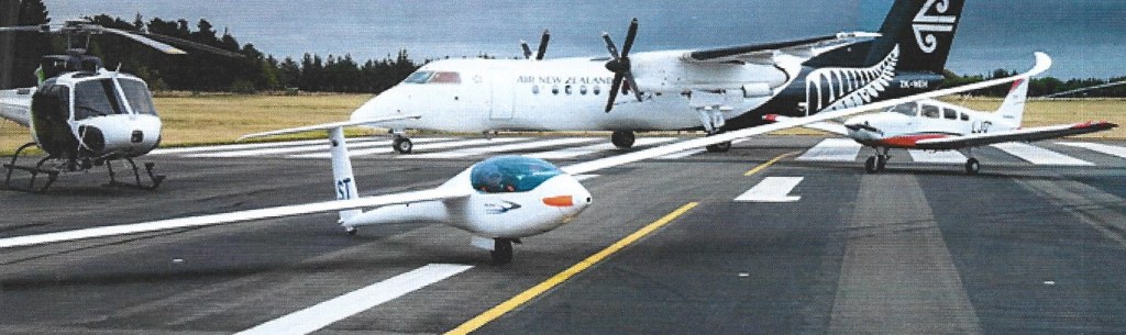
Issoire, part of the groupe Siren, acquired a license from Eiri Avion to build the 15 m. self- launching Finnish PIK 20E designed by Pekka Tammi and M.Moniot. The Pik 30 is a self- launching 17 m. development which first flew in 1984. It has the capability of being flown as a 15 m. sailplane or, with tip extensions, with 17 m. span. The PIK 30 has a mast mounted manually actuated retractable engine.
Construction of the wings and tail surfaces: GFRP sandwich with PVC core; carbon fiber spar caps and cockpit sides: GFRP monocoque structure reinforced with ribs of carbon fiber.

SIREN PIK-30 ZK-GST

Span: 17m / 55.8ft
Area: 10.63sq.m / 114.42sq.ft
Empty Weight: 340kg / 750lb
Payload: 120kg / 264lb
Gross Weight: 460kg / 1014lb
Wing Load: 43.27 kg
/sq.m / 8.86 lb/sq.ft
Water Ballast: 0
Aspect ratio: 27.2
L/DMax: 45 110 kph / 59 kt / 68 mph
MinSink: 0.54 m/s / 1.77 fps / 1.05 kt
Airfoil: Wortmann FX-67 K170, root, K150, tip
Engine: 32 kW/ 43 bhp Rotax 503
Seats: 1
No. Built: 10