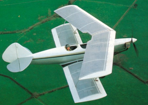
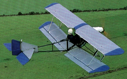
Wallace and Robert McNair started the Mynah II design in Septem¬ber 1988, intended right from the start for series production, a two seater at the top end of the microlight performance range. This aircraft had no commonality with the earlier single seat Mynah aircraft, although both were designed by Wallace and Robert McNair of Auckland, New Zealand.
The fuselage is a one piece moulded fibreglass unit, with integral verti¬cal fin and bottom wing fairings. Moulded in at construction time are wooden longerons, to which the engine mount is bolted at the firewall, and strength is added by the compound curves everywhere, the only straight surface being on the bottom be¬tween the wings. Bulkheads are located around the cockpits and form the structural unit on which the wings, struts, wires and fibreglass landing gear legs are mounted.
The wings, of Clark Y aerofoil, have folded aluminium channel extrusions for the spars, pressed aluminium ribs and Mylar covering, an aluminium leading edge, laced along the lead¬ing edge and each end, with the lacing covered by tips and leading edges, applied after covering. They have marked forward stagger, the bottom wing rear spar passing behind the rear seat and the top wings with a large amount of sweepback to keep the centre section well forward, clear of the front cockpit. Fuel tanks with a total capac¬ity of 50 litres are incorporated in the in¬board ends of the bottom wing leading edges.
Everything is designed around the 390 kg microlight category and standard 4G loading. Empty weight is 170 kg, allowing a pay¬load total of 220 kg, plenty for two occu¬pants, full fuel and a bit more. The Mynah II has a safe endurance of two and a half hours. Motive power is a two cylinder horizon¬tally opposed two stroke Arrow engine from Italy, pulling 65 hp at 6800 rpm, with the three blade carbon fibre propeller of 66 in diameter geared down at 2.77/1.
It was designed with an eye to production but this never eventuated.
ZK-FWT (c/n 001/MAANZ/450) was built by the McNairs and also by Alan Stewart of Tuatapere, to whom the aircraft was first registered on 25/10/90. It flew well with a cruise of around 70 mph. Empty weight was around 220 Kg and MAUW was 449 Kg.
It was sold to RA Hansen of Huntly on 30/8/93. It is still registered and it is kept in a hangar at Glen Murray, although I believe it hasn’t flown for several years.
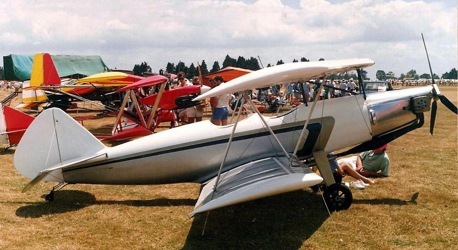
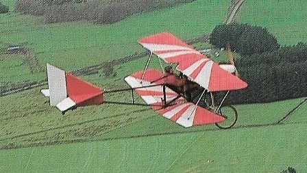
Designed and built by Wallace McNair, Auckland, NZ, and owing much to the Lincoln Sports design, the Mynah has a unique folding fuselage for transportation by trailer. The wings are therefore able to be permanently rigged while the wire bracing from the wing struts to the rear fuselage takes only a matter of minutes to rig. The engine is a two-cylinder “half-a-VW”.
Hi I currently own the mcnair mynah pictured and one partialy built, mine has a rotax 447 engine although i have seen one with a 503 rotax. There were about 6 built and 3 in flying condition that i know of. Michael Jones 13 December 1013
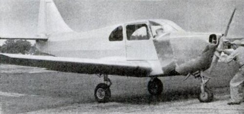
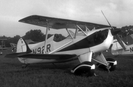
Transocean Air Lines subsidiary, Mckinnie Aircraft, developed the all-metal two-seat side-by-side McKinnie 165 with Franklin engine, first flown August 10,1952.
All structural components are of full cantilever construction and are fabricated from aluminium-clad sheet. The McKinnie 165 is fully aerobatic and dual controls are fitted.
Engine: 165 hp Franklin 6A4-165-B3 Wingspan: 23 ft 6 in Length: 18 ft 3 in Height: 7 ft Empty weight: 1200 lb Loaded weight: 1840 lb Max speed: 175 mph at SL Cruise: 160 mph ROC: 1550 fpm Range: 720 mi at 170mph at 8000 ft Range: 1050 mi at 150mph
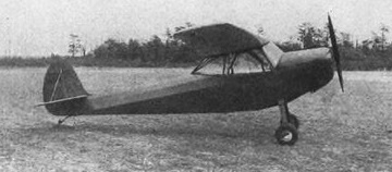
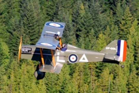
Dan McGowan and “Gogi” Goguillot of Yarrow, B.C., Canada, designed this 7/8 scale replica of the famous World War 1 British Fighter built by the Royal Aircraft Factory. While changes had to be made to accommodate a full size pilot, and an alternate engine chosen when designing the scaled down version as an amateur built sport plane, the replica does resemble the original. It is represented as a much modified, scaled down sport plane, and not a true replica of the original fighter. Use of a modern 4 cylinder 85 hp Continental engine required a cowling to simulate the original water cooled 200 hp geared Hispano engine, but provides a practical solution for every day operation. This airplane was built by Dan McGowan at Richmond, B.C. and was flown regularly since its construction in 1970, and was a regular participant in homebuilt flypasts at airshows. Donated to the Canadian Museum of Flight by Dr. Fred Hemming of Vancouver in 1983. This aircraft was returned to flying condition by the Canadian Museum of Flight and since 1997 once again participated in airshows.
Serial 002, CF-QGL Engine: Continental C-85, 85 hp Cruise speed: 90 mph (145 km/h) Empty weight: 790 lb (358 kg) Loaded weight: 1,100 lb (499 kg) Span: 22 ft 10 in (6.9 m) Length: 14 ft 4 in (4.3 m) Height: 7 ft 2 in (2.2 m)
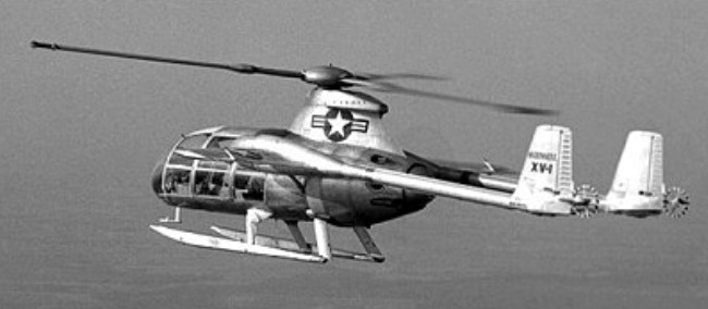
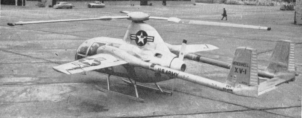
Initially designated XL-25 in the liaison aircraft category, then XH-35 in the helicopter class, and finally XV-1 as the first type in the new vertical lift category of aircraft designations, this machine worked on the unloaded rotor principle. Designed by Friedrich von Doblhoff, the Austrian helicopter pioneer responsible for the wartime WNF 342, the XV-1 was the result of an experimental programme undertaken jointly by McDonnell, the US Army Transportation Corps, and the USAF Air Research and Development Command.
Initiated by a Letter of Intent dated 20 June, 1951, the XV-1 project proceeded through mock-up inspection in November 1951, and the first aircraft (53-4016) was completed some 22 months later.
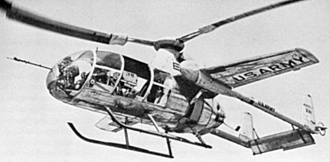
Combining the features of a twin-boom, twin-tail, fixed-wing aircraft with those of a single-rotor helicopter, the XV-1 was powered by a 525hp / 391kW Continental R-975-19 seven-cylinder radial. For vertical flight this engine drove two compressors which fed air through tubes to small pressure jets at the tips of the three-blade rotor, with the pressure jets operating on the principle of ignition and expansion of the fuel gases. For forward flight, the engine drove a two-blade pusher propeller mounted aft of the fuselage between the tail booms while the rotor autorotated. The XV-1 was intended to take-off and land as a helicopter, with transition from helicopter flight mode to conventional flight being made by transferring power from rotor to propeller as soon as the forward speed exceeded the stalled speed of the wing. Side-by-side accommodation was provided for a pilot and a co-pilot with room behind them for test instrumentation. Alternatively, accommodation could have been provided for a pilot and three passengers or a pilot and two stretchers.
The 9m long fuselage, mounted on skid landing gear, and mid/high-set wings mounted twin tailbooms with twin vertical surfaces (about 3m in height), inter-connected by tailplane and elevator.
The 7.9m span fixed wing featured a slight sweep on both the leading and trailing edges, although the angle of sweep was greater on the leading edge. It was also designed with a high aspect ratio and joined the fuselage at the same level as the top of the cockpit, directly below the mounting for the upper rotor. The wing terminated in the fuselage into a large bulbous housing on either side of the fuselage.
Project test pilot John R. Noll began tethered hover flights on 11 February, 1954, but difficulties with the pressure jet system delayed initial free flight until 14 July, 1954. The first successful transition from helicopter flight to conventional flight was made on 29 April, 1955. The flight test programme revealed several design deficiencies which were progressively corrected through the introduction of such modifications as a cut-down rotor pylon, small anti-torque rotors fixed to the end of each taitboom, redesigned landing skids, and other minor detail changes. During the preceding months, the second XV-1 (53-4017) had joined the flight trials programme. This machine differed from the first prototype in having a bulkier but streamlined undercarriage and cut-down rotor pylon to reduce interference drag. Numerous detail improvements, including the addition of a small steering rotor behind each boom, were progressively incorporated.
In evaluating the program, the consensus was that the basic concept was sound, but the piston engine powerplant could not provide the needed performance to optimize the design. It was felt that use of a gas turbine engine in this application would solve the problem.
Although on 10 October, 1956, the second prototype XV-1 had become the world’s first rotary wing vehicle to reach a speed of 322km/h, the gain in performance over conventional helicopters did not warrant the added complexity of the convertiplane configuration. Furthermore, the potential of the McDonnell XV-1 was seriously limited by its use of a piston engine instead of gas turbines as adopted to power European convertiplanes which preceded or followed it.
The programme was terminated in 1957 after the two prototypes had been flown for a total exceeding 600 hours. The first XV-1, 53-4016, then went to the Army Aviation Center Museum at Fort Rucker, Alabama, and the second, 53-4017, was donated to the Smithsonian Institution’s National Air and Space Museum, in Washington, DC.