Mitchell P-38 / AG-38

P-38

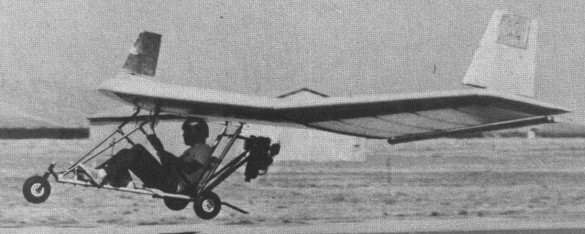
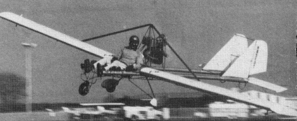
Single seat single engined mid wing monoplane with conventional three axis control. Wing has unswept leading and trailing edges, and constant chord; two fin tail. Pitch control by fully flying tail; yaw control by fin mounted rudders; roll control by full span ailerons also usable as flaps; control inputs through stick for pitch/roll and pedals for yaw. Wing braced from above by struts, wing profile NACA 23015; double surface. Undercarriage has three wheels in tricycle formation, with addi¬tional tailskids; steel spring suspension on nosewheel and glass fibre suspension on main wheels. Push right go right nosewheel steering connected to yaw control. Brake on nosewheel. Aluminium tube/wood/steel tube framework, with optional pod. Engine mounted above wing driving pusher propeller.

Mitchell P-38 Article

The P 38 was designed by Jim Meade and christened Lightning after the famous twin boom fighter of the Second World War. The prototype appeared at the end of 1980 and the first P 38 was sold during the second quarter of 1981. The prototype was fitted with a 26.0ft (7.92m) span wing having a 4.0ft (1.22m) chord, giving 104sq.ft (9.7 sq.m) of wing area using the same NACA 23015 profile as the B 10. With 200 lb (91 kg) empty weight and 450 lb (204 kg) maximum gross weight, this machine carried 250 lb (113 kg) useful load with a wing loading of 4.32 lb/sq.ft (21.1 kg/sq.m).

On the production models, the wing span was increased to 28.0ft (8.53m) and the chord also increased.
Initially fitted with a Honda Odyssey engine of 250 cc giving 20 hp, or as an option a Zenoah G25B also of 20 hp, the P 38 was in 1983 powered by the twin cylinder Cuyuna 430RR 30 hp engine. Its characteristics and performance figures do not allow its classification as an ultralight, so it is therefore necessary to hold at least a private pilot’s licence to fly the Lightning in the US.

The complete kit, requiring 80 h for assembly, has less than 200 pieces, the principal components being prefabricated and partly assembled. The wing ribs are wood, bonded with epoxy to the tubular Duralumin spar, while the leading edges are of polyurethane foam shaped and then covered with birch plywood. On the P 38, the ‘flaperons’ a combination of flap and aileron are made with ribs every 6 inch (15 cm). Like the other Mitchell models, this one is also available as an economy kit or as plans only.

Units delivered by June 1981 35 kits and plans.

The AG 38 is the crop spraying version of the P 38 Lightning, to which it is very similar except a pod is fitted. The prototype AG 38 was shown to the public during the EAA Convention at Oshkosh in August 1982. This aircraft is fitted with Micron X15 100 variable speed rotating nozzles, which are said to control droplet size and so reduce the amounts of chemical and water required. They are supplied from a shaped tank which carries 14.0 US gal (11.7 Imp gal, 53.0litre) of spray chemical. The tank is fitted under the seat and central wing section, between the legs of the main landing gear. An electric pump feeds the spray booms which are fitted with 19 fan nozzles across the full wing span. For a better spread, the two spray bars are placed at not the trailing edge as is usual, but 9.5 inch (24 cm) below the level of the wing.

At 50mph (80kph) the AG 38 spray swath varies from 20ft (6m) wide at 6ft (2m) altitude to 45 ft (14 m) wide at 15 ft (5 m) altitude. With the equipment set for maximum delivery, the AG 38 can deliver 48oz/acre (3.4 litre/hectare) and can treat 37 acre (15 hectare) per load. Reloading is required every 30 min, allowing an average coverage of 60 acre/h (24 hectare/h). At the other end of the scale, the machine can be set up for maximum acreage, when it will deliver 6oz/acre (0.42 litre/hectare) and treat 300 acre (120 hectare) per load. Reloading is required approximately every 2h, giving an average coverage of 140 acre/h (56 hectare/h).

P-38
Engine: Cuyuna 430RR, 35 hp at 5500 rpm
Power per unit area 0.29 hp/sq.ft, 3.1 hp/sq.m
Length overall 17.0ft, 5.18 m
Height overall 5.0ft, 1.52m
Wing span 28.0ft, 8.53m
Constant chord 4.3 ft, 1.29 m
Sweep forward 5 deg
Total wing area 120 sq.ft, 11.2 sq.m
Wing aspect ratio 6.5/1
Wheel track 5.0 ft, 1.52 m
Nosewheel diameter overall 10 inch, 25 cm
Main wheels diameter overall 10 inch, 25 cm
Empty weight 305 lb, 138kg
Max take off weight 700 lb, 317kg
Payload 395 lb, 179kg
Max wing loading 5.83 lb/sq.ft, 28.4 kg/sq.m
Max power loading 20.0 lb/hp, 9.lkg/hp
Load factors; +4.0, 4.0 ultimate
Max level speed 65 mph, 105 kph
Max cruising speed 55 mph, 88 kph
Stalling speed 32 mph, 51 kph
Max climb rate at sea level 500 ft/min, 2.5 m/s
Min sink rate 400 ft/min, 2.0 m/s
Best Wide ratio with power off 7/1
Take off distance 210ft, 64m
Landing distance 250ft, 76m
Service ceiling 12,000ft, 3660m
Range at average cruising speed 110 mile, 177 km

AG-38
Engine: Cuyuna 430RR, 35 hp at 5500 rpm
Power per unit area 0.29 hp/sq.ft, 3.1 hp/sq.m
Length overall 17.0ft, 5.18 m
Height overall 5.0ft, 1.52m
Wing span 28.0ft, 8.53m
Constant chord 4.3 ft, 1.29 m
Sweep forward 5 deg
Total wing area 120 sq.ft, 11.2 sq.m
Wing aspect ratio 6.5/1
Wheel track 5.0 ft, 1.52 m
Nosewheel diameter overall 10 inch, 25 cm
Main wheels diameter overall 10 inch, 25 cm
Empty weight 325 lb, 147kg
Max take off weight 700 lb, 317kg
Payload 375 lb, 170kg
Max wing loading 5.83 lb/sq.ft, 28.4 kg/sq.m
Max power loading 20.0 lb/hp, 9.lkg/hp
Load factors; +4.0, 4.0 ultimate
Max level speed 65mph, 105kph
Stalling speed 35mph, 56kph
Max climb rate at sea level 500ft/min, 2.5 m/s
Take off distance 275 ft, 85 m
Landing distance 325 ft, 100 m
Mitchell A-10

Mitchell A-10 Silver Eagle

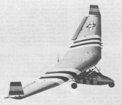
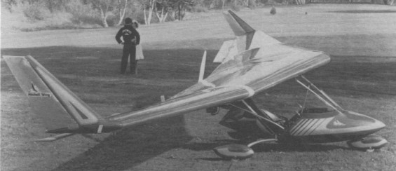
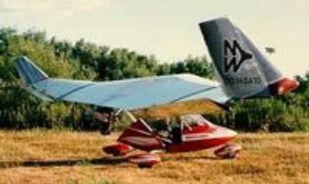
Single seat single engined high wing monoplane with conventional three axis control. Wing has swept back leading and trailing edges, and tapering chord; no tail. Pitch/roll control by stabilators; yaw control by tip rudders; control inputs through stick for pitch/roll and pedals for yaw. Cantilever wing; wing profile; double surface. Undercarriage has three wheels in tricycle formation. Push right go right nosewheel steering connected to yaw control. Aluminium tube framework, with pod. Engine mounted below wing driving pusher propeller.

Shown in December 1982, the A 10 Silver Eagle is an updated version of the B 10 Mitchell Wing, not only as regards detail improvements, but in the technology and type of manufacture. Don Mitchell has abandoned the overhead stick, which comes down from the high wing on the B 10, to replace it with a conventional stick between the pilot’s knees. Materials (wood and fabric) used for the B 10 wing have been superseded by aluminium and a foam developed by NASA called honeyfoam and designated SR 502B, the final B indicating the use of boron.

The A 10 Silver Eagle was sold ready to fly and includes a fairing for the cockpit, wheel fairings on the main wheels, an upholstered seat with shoulder harness and an instrument panel. The price in April 1983 was $5995.

Mitchell Wing A-10

Ameriplanes Inc sold the Mitchell Wing A-10 described as a unique, ultralight motorglder for intermediate and advanced pilots based on Don Mitchell’s Mitchell Wing B-10 hang glider. It is a flying wing design from aluminium. It utilzes a Rotax 277/28 hp engine and was available in kit form for $9400 (does not include engine). Price completed in 2009: 11700 USD

The A-10 was available with a 2SI, A-20 engine and when equiped with same it comes in at 254lbs (the 103 UL limit). Other engines, like the Zenoah G25B-1 were also available.

The Higher Planes A-10 is stressed to +6 and –5.5 G, and the wings fold for transport. The kit price in 1997, without engine, was US$7900.

A-10
Engine: Zenoah 250 (242cc) 23hp
Static thrust: 160 lbs
Empty wt: 250 lbs
Wing span: 34’4”
Wing area: 134 sq.ft
Height: 6’2”
Length: 8’6”
Fuel cap; 3 USG
Construction: Aluminium, Boron, Foam
Max wt: 553 lbs
Stall speed: 27 mph
Max speed: 63 mph
Vne: 63 mph
Climb rate: 640 fpm @ 41 mph
Design limit: +5.5, -5.5g
Glide ratio: 15-1
Wing loading: 4.13 lbs/sq.ft
Power loading: 24.04 lbs/hp

Engine: Rotax 277, 26 hp
Speed max: 70 mph
Cruise: 55 mph
Range: 200 sm
Stall: 28 mph
ROC: 800 fpm
Take-off dist: 200 ft
Landing dist: 200 ft
Service ceiling: 12,000 ft
Fuel cap: 2.5 USG
Weight empty: 280 lbs
Gross: 553 lbs
Height: 7.33 ft
Length: 9.33 ft
Wing span: 34.33 ft
Wing area: 134 sq.ft
Seats: 1
Landing gear: nose wheel

A-10 Silver Eagle
Engine: Zenoah G2SB 1, 20 hp at 6500 rpm
Toothed belt reduction
Max static thrust 165 lb, 75 kg
Power per unit area 0.14 hp/sq.ft, 1.58 hp/sq.m
Fuel capacity 3.0 US gal, 2.5 Imp gal, 11.4 litre
Length overall 8.0ft, 2.43m
Height overall 5.6 ft, 1.67m
Wing span 34.4ft, 10.46m
Chord at root 6.0ft, 1.83m
Chord at tip 2.0ft, 0.61m
Dihedral 6 deg at tip
Sweepback 12 deg
Total wing area 136 sq.ft, 12.6sq.m
Wing aspect ratio 8.6/1
Nosewheel diameter overall 10 inch, 25 cm
Main wheels diameter overall 10 inch, 25 cm
Empty weight 250 lb, 113kg
Max take off weight 553 lb, 251 kg
Payload 303 lb, 138 kg
Max wing loading 4.06 lb/sq.ft, 19.8 kg/sq.m
Max power loading 27.6 lb/hp, 12.5 kg/hp
Load factors +6.0, 6.0 design
Max level speed 63 mph, 101 kph
Max cruising speed 58 mph, 93 kph
Stalling speed 26 mph, 42 kph
Max climb rate at sea level 650 ft/min, 3.3 m/s
Best glide ratio with power off 18/1
Take off distance 200ft, 60m
Landing dis¬tance 200 ft, 60 m

Ameriplanes Mitchell Wing A-10
Engine: Rotax 277, 28 hp
Wing span: 34.33 ft
Wing area: 156 sq.ft
Empty Weight: 115 kg / 254 lbs
MTOW Weight: 249 kg / 550 lbs
Stall: 24 kt / 28 mph / 45 kmh
Cruise: 52 kt / 60 mph / 97 kmh
VNE: 66 kt / 76 mph / 122 kmh
L/D: 16:1
Sink rate: 240ft/min.

Higher Planes Mitchell Wing A-10
Engine: Rotax 277, 26 hp
HP range: 22-26 hp
Top speed: 70 mph
Cruise: 55 mph
Stall: 28 mph
Range: 200 sm
Rate of climb: 800 fpm
Takeoff dist: 200 ft
Landing dist: 200 ft
Service ceiling: 12,000 ft
Fuel capacity: 2.5 USG
Empty weight: 280 lb
Gross weight: 553 lb
Height: 7.3 ft
Length: 9.3 ft
Wing span: 34.3 ft
Wing area: 134 sq.ft
Seats: 1
Landing gear: nose wheel

Mitchell B40F

A hang gliding fanatic, Dr H Long, gave Don Mitchell control of a high performance wing. By 1975 this same wing had become the B 10. The first powered version now carries the designation of B40F (F for foot launch).
The aircraft is in effect a wing, supporting beneath its lower surface a rigid frame formed by two sets of struts in the shape of an N, at the back of which is mounted a McCulloch Mc101 12hp engine with direct drive to a two blade pusher propeller.

The addition of a go-kart engine and streamlined pilot pod has turned the design into a high-performance ultralight. It is fast, sensitive and very maneuverable. The wing is wooden and built up in a typical “D” Section cantilever, with pilot cage attached underneath and a pusher prop in the rear. Top speed is about 55 mph, and climbout is around 350 fpm. It can be foot-launched, but the added weight of an engine and its accessories make it wise to consider tricycle gear. A Mac 101 engine swings a 42-inch prop and sips two gallons of gas in two hours.

Mitchell B-10 / XF-10

Single seat single engined high wing mono¬plane with conventional three axis control. Wing has swept back leading and trailing edges, and tapering chord; no tall. Pitch/roll control by stabilators; yaw control by tip rudders; control inputs through stick for pitch/roll and pedals for yaw. Cantilever wing: wing profile NACA 23015; double surface. Undercarriage has three wheels in tricycle formation; suspension on all wheels. Push right go right nosewheel steering con¬nected to yaw control. Optional brake on nosewheel.

Mitchell B-10 Article

Aluminium tube/wood/steel tube framework, with optional pod. Engine mounted below wing driving pusher propeller.

A hang gliding fanatic, Dr H Long, gave Don Mitchell control of a high performance wing. By 1975 this same wing had become the B 10. The first powered version now carries the designation of B40F (F for foot launch).
The aircraft is in effect a wing, supporting beneath its lower surface a rigid frame formed by two sets of struts in the shape of an N, at the back of which is mounted a McCulloch Mc101 12hp engine with direct drive to a two blade pusher propeller.

Very quickly Don Mitchell fitted the framework with a tricycle undercarriage with a nosewheel steered by the rudder bar, while a more elaborate version of the B 10 was shown at Oshkosh in August 1981, fitted with a glass fibre fairing and main wheel spats. By 1980, more than 500 sets of plans or kits for the B 10 had been sold. Previously only sold as sets of plans or as a kit, the B 10 Mitchell Wing has been offered factory built, since September 1982.

The structure of each wing has five central ribs in a wooden lattice with six ribs on either side, all of quite conventional construction. The thick plywood spar has D shaped pieces of polyurethene foam resting on it every 4.3 inch (11 cm), which are then covered in 0.04 inch (l mm) thick sheets of plywood to form the leading edge. The control surfaces are made in the same way except for the rudders which have a tubular metallic spar. The covering is of Dacron or aviation quality Ceconite.

Due to the absence of a tail, roll and pitch control are both provided by stabilators, which span most of each half wing. Controlled from the stick, these stabilators act differentially like ailerons and together as elevators, while the rudders can also act as air brakes. The B 10 Mitchell Wing has dropped the Mc101 engine in favour of the Zenoah G25B. According to Mitchell Aircraft, con¬struction requires 250h of work. The 1983 prices are $6995 ready built, economy kit $1995 (without engine, instru¬ments and undercarriage), homebuilder’s kit $1295 (including raw materials and all hard¬ware but without engine, undercarriage, paint or glue), power pack $1595, tricycle undercarriage $495 and plans $125.

Units and plans delivered by June 1981 1,200 + kits.

Basically a strengthened B 10, the 1981 prototype of the XF 10 was originally shown by Mitchell Aircraft under the name of SR 10 and is a modified version of the B 10 Mitchell Wing, intended for the military market. This machine is today offered as a kit for an extra $1100 on top of the price of a B 10, compared with which the XF 10 is structurally reinforced and has a faired cockpit as standard. Like the standard B 10, the XF 10 uses the single cylinder Zenoah G2513 1.

Plans for the Mitchell wing B-10 became available from Richard Avalon at US Pacific, 892 Jenevein Ave., San Bruno, CA 94066. The B-10 has held world records by George Worthington. Richard worked with Don just before Don’s death and was not able to carry forward with some planned designs, but Richard is offering Don’s plans.

The Mitchell B-10J is a package available from Jim Gordon’s Micro Aviation. The US$5200 package includes a Garrett JFS100-13 originally used as a starter for the TF-41 engine in the A-7 Corsair. Including throttle package, lubrication and tailpipe assembly, the engine weight is 53 lb, and replaces the Zenoah. First flights were in February 1996, with 80 lb thrust.

Variation:
Bremner Mitchell B10 Wing Special

B-10
Engine: Zenoah G2SB 1, 23 hp at 6500 rpm
Propeller diameter 44 inch, 1.11 m
Toothed belt reduction, ratio 3.0/1
Max static thrust 165 lb, 75 kg
Power per unit area 0.17hp/sq.ft, 1.8hp/sq.m
Fuel capacity 3.0 US gal, 2.5 Imp gal, 11.4 litre
Length overall 6.0ft, 1.83 m
Height overall 4.0ft, 1.21m
Wing span 34.0ft, 10.36m
Chord at root 6.0ft, 1.83 m
Chord at tip 2.0 ft, 0.61 m
Dihedral (On outboard part of wing) 6 deg
Sweepback 12 deg
Total wing area 136 sq.ft, 12.6 sq.m
Wing aspect ratio 8.5/1
Nosewheel diameter overall 10 inch, 25 cm
Main wheels diameter overall 10 inch, 25cm
Empty weight 185 lb, 84kg
Max take off weight 525 lb, 238kg
Payload 340 lb, 154kg
Max wing loading 3.86 lb/sq.ft, 18.8kg/sq.m
Max power loading 22.8 lb/hp, 10.3kg/hp
Load factors; +4.2 ultimate
Max level speed 55 mph, 88 kph
Max cruising speed 45 mph, 72kph
Stalling speed 25mph, 40kph
Max climb rate at sea level 300 ft/min, 1.5 m/s
Min sink rate 225ft/min at 35mph, 1.1m/s at 56 kph
Best glide ratio with power off 16/1
Take off distance 175ft, 53m
Landing distance 175 ft, 53 m
Service ceiling 12,000 ft, 3648 m
Range at average cruising speed 135 mile, 217 km

XF 10
Engine: Zenoah G2SB 1, 23 hp at 6500 rpm
Propeller diameter 44 inch, 1.11 m
Toothed belt reduction, ratio 3.0/1
Max static thrust 165 lb, 75 kg
Power per unit area 0.17hp/sq.ft, 1.8hp/sq.m
Fuel capacity 6.0 US gal, 5.0 Imp gal, 22.7 litre
Length overall 6.0ft, 1.83 m
Height overall 4.0ft, 1.21m
Wing span 34.0ft, 10.36m
Chord at root 6.0ft, 1.83 m
Chord at tip 2.0 ft, 0.61 m
Dihedral (On outboard part of wing) 6 deg
Sweepback 12 deg
Total wing area 136 sq.ft, 12.6 sq.m
Wing aspect ratio 8.5/1
Nosewheel diameter overall 10 inch, 25 cm
Main wheels diameter overall 10 inch, 25cm
Empty weight 200 lb, 91kg
Max take off weight 600 lb, 272kg
Payload 400 lb, 181kg
Max wing loading 4.41 lb/sq.ft, 21.5 kg/sq.m
Max power loading 26.1 lb/hp, 11.8kg/hp
Never exceed speed 50mph, 80kph
Stalling speed 25mph. 40 kph

B-10J
Engine: Garrett JFS100-13, 80 lb thrust
Fuel burn: 10 USGPH
Fuel capacity: 3.5 USG
Endurance: 20-30 min

Mission Aircraft Morrison 6 / Barr 6

The airframe is designed around the efficiency of the 8 cyl Lycoming engine the engine prop combination produces a balance of objectives that allows speed, service and the freedom of no flight restrictions.

All skins of the Morrison 6 kit are made with 7781 e-glass prepreg and epoxy resin content of 36 to 38 %, vacuumed bagged and cooked at 250 degrees, plus the fibers in the prepreg stay in a straight line making for a stronger skin. Nomex core wrapped in adhesive. Designed for ease of assembly. Pre-cured graphlite carbon rod packs are built into the structure to carry the designed loads. The advantage of the rods is that the fibers in the rods are straight and will test out to the tinsel strength designed.

Morrison 6
Engine: Lycoming IO-720 A1BD, 400 hp
Recommend TBO: 1800 hr
HP range: 400-450
Propeller: Hartzell Constant Speed HC-E3YR-1RF/F8468A-6R
Propeller Diameter: 83 in
Propeller Ground Clearance: 9.75 in
Length: 29 ft 11 in
Height: 7 ft 2 in
Wingspan: 35 ft 10 in
Wing Area: 174 sq.ft
Stabilizer span: 13 ft 0 in
Stabilizer: 24.84 sq.ft
Elevators: 20.09 sq.ft
Vertical fin: 12.00 sq.ft
Aileron: 17.32 sq.ft
Flaps: 29 sq.ft
Wing airfoil: Modified NACA 2412
Ailerons: Frieze Type Wide – Chord
Flaps: NACA Single Slotted
Wing Aspect Ratio: 7.63
Wing Chord: Root 64″ Tip 42″
Diheadral: 1° 44′
Wing Loading: 25.9 lb./sq.ft
Power Loading: 11.25 lb./hp
Span Loading: 125.9 lb./ft
Empty Weight: 2197-2501 lb
Gross Weight: 4500 lb
Useful Load: 2303 – 1999 lb
Wing Root Incidence: +1° 30′
Wing Tip Incidence: -1° 30′
Stabilizer Incidence: -3° 0′
Engine Incidence: -3° 30′
Front Seats: 52″
Center Seats: 52.5″
Rear Seats: 44″
Rear Baggage: 38″
Cabin Height: 49″
Seats: 6
Pilot Door: 3′ 4″ x 3′ 1″
Double Cargo Door: 3′ 2-1/2″ x 3′ 8-1/8″
Std. Fuel Capacity: 90 USgal
Optional Fuel Capacity: 140 Usgal
Land Gear Options: tail wheel, floats, skis
Controls: duel control yokes
Max Forward C/G: 33.0″
Max Aft. C/G: 49.7″
Ref. Datum: Lower Front Face of Firewall
Vne: 248 MPH
Vc: 206 MPH
Va: 171 MPH
Cruise: 206 mph
Stall: 62 mph
Range: 1660 sm
Rate of climb: 900 fpm
Takeoff dist: 900 ft
Landing dist: 750 ft

Mirage Aircraft Marathon

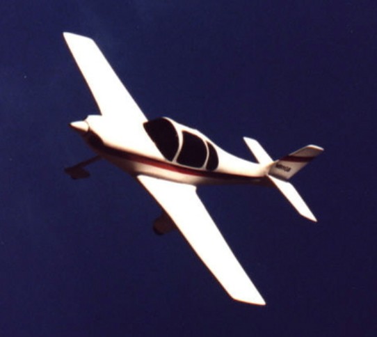
The Marathon is a high performance, 2-place side-by-side plans built airplane with fixed tricyle landing gear. Constructed primarily of wood and fiberglass covering, the Marathon cruises at about 185 mph range on 150hp and has a range of over 900 miles. Engines range from 150 to 180hp.

The builder has the choice of carrying all the fuel in the wing, or sleek tip tanks can be installed.

Complete landing gear assemblies and other finished components were available from Mirage Aircraft. Six construction videos are also available.

The complete set of plans, videos, and construction manual guide you through the project, teaching you the skills as you go.

The Marathon is patterned after the Celerity, which was designed by Larry Burton.

Engine: Lycoming O-320, 150 hp
Cruise: 185 mph
Range: 900 miles
HP range: 150-180
Wingspan: 25ft
Length: 21 ft 10in

Mirage Aircraft Celerity

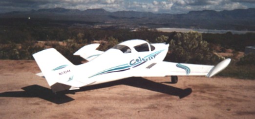
The Celerity was designed by Larry Burton, who flew the prototype in 1985 and won an Oshkosh workmanship award that same year. The prototype has accumulated over 900 hours. It is designed to be built by the average person, with average skills, at low cost, yet perform as well as the most expensive kit airplanes in it’s class.

The Celerity is a high performance, 2-place side-by-side plans built airplane with fully retractable landing gear, including the tail wheel. It can also be built as the “Marathon” with fixed tricycle gear. Designed for builders with average skills, both aircraft are constructed from wood with fiberglass covering. Six construction videos were available. Celerity cruises in the 200 mph range on 150 to 180 hp and has an operating range of more than 750 miles with fuel reserve. The builder has the choice of carrying all the fuel in the wing, or sleek tip tanks can be installed.

Complete landing gear assemblies and other finished components were available from Mirage Aircraft.

Engine: Lycoming O-320, 160 hp
HP range: 150-180
Height: 5.5 ft
Length: 21 ft 10 in
Wing span: 25 ft
Wing area: 100 sq.ft
Weight empty: 1169 lb
Gross: 1800 lb
Fuel cap: 44 USG
Speed max: 220 mph
Cruise: 205 mph
Range: 1000 sm
Stall: 50 mph
ROC: 1800 fpm
Take-off dist: 800 ft
Landing dist: 1000 ft
Service ceiling: 20,000 ft
Seats: 2
Landing gear: retractable tail wheel