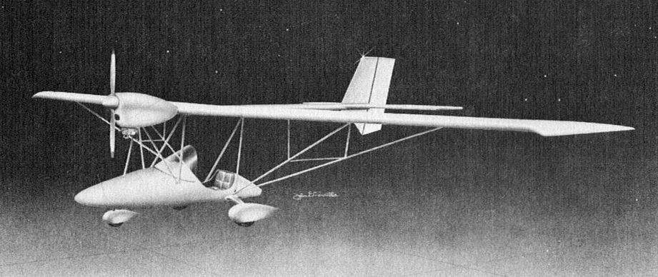
Single seat single engined high wing mono¬plane with conventional three axis control. Wing has elliptical planform and tapering chord; inverted V tail. Pitch/yaw control by elevon; roll control by wing warping; control inputs through stick for pitch/roll and pedals for yaw. Cantilever wing; wing profile; double surface. Undercarriage has three wheels in tricycle formation; suspension on all wheels. Push right go right nosewheel steering connected to yaw control. No brakes. Aluminium tube framework, without pod. Engine mounted below wing driving pusher propeller.
Conceived by J Bruce Emmons, the Eclipse was one of the new releases at Sun ‘n’ Fun of March 1983 at Lakeland, Florida. The Eclipse is also the first rigid wing ultralight to use wing warping for roll control (with the possible exception of the British Ladybird, which is not yet in production). With the Eclipse, the accent has been put on flight stability. The strength of the airframe has not been neglected, this ultralight having been static tested to as much as ± 9 g, more than the requirements for a light aircraft to be classed in the aerobatic category. The wings can be placed parallel with the framework by removing three bolts; demounted like that the machine can be transported either on a trailer or a roof rack. All the pieces in the kit are delivered pre formed, cut and drilled. Sold for $5495 in 1983, the kit thus provided is claimed to need only 30 h for completion.
Engine: KFM 107, 25 hp at 6000 rpm Propeller diameter and pitch 54×23 inch, 1.37×0.58m V belt reduction, ratio 2.0/1 Max static thrust 175 lb, 79 kg Power per unit area 0.22 hp/sq.ft, 2.4hp/sq.m Fuel capacity 5.0 US gal, 4.2 Imp gal, 18.9 litre Length overall 14.0 ft, 4.27 m Height overall 5.0ft, 1.52m Wing span 32.2ft, 9.80m Chord at root 4.0 ft, 1.22 m Dihedral 0 deg Tailplane span 8.0 ft, 2.44 m Total wing area 114 sq.ft, 10.6 sq.m Wing aspect ratio 9.1/1 Wheel track 4.0 ft, 1.22 m Wheelbase 6.0 ft, 1.83 m Nose¬wheel diameter overall 11 inch, 27 cm Main wheels diameter overall 11 inch, 27 cm Empty weight 165 lb, 75kg Max take off weight 465 lb, 211kg Payload 300 lb, 136kg Max wing loading 4.071b/sq.ft, 19.9kg/sq.m Max power loading 18.6 lb/hp, 8.4kg/hp Load factors +6.0, 6.0 design; +9.0, 9.0 ulti¬mate Max level speed 63 mph, 103kph Max cruising speed 55 mph. 88kph Economic cruising speed 50mph. 80kph Stalling speed 25mph, 40kph Best glide ratio with power off 15/1 at 35mph. 56kph Range at average cruising speed 150 mile, 241 km
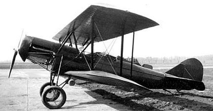
The 1929 Phantom Knight Aircraft Co A-150 was a three-place, open cockpit biplane powered by a Hisso engine. Registered N12922 c/n 2, the gross weight was 2450 lb, and claimed top speed was 105 mph, cruise 90 mph, and stall 30 mph. The claimed range was 620 miles.
During 1928 the Phantom Knight Aircraft Co built a three-place, open cockpit biplane powered by a 90hp Curtiss OX-5 engine. The aircraft was registered NX7927 c/n 1.
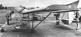
Single seat single engined high wing monoplane with conventional three axis control. Wing has unswept leading and trailing edges, and constant chord; cruciform tail. Pitch control by elevator on tail; yaw control by fin mounted rudder; roll control by half span ailerons; control inputs through stick for pitch/roll and pedals for yaw. Wing braced from below by struts; wing profile; double surface. Undercarriage has three wheels in tricycle formation; suspension on all wheels. Push right go right nose-wheel steering connected to yaw control. Aluminium tube/steel tube framework, with optional pod. Engine mounted at wing height driving tractor propeller.
This prototype was undergoing an intensive test flying programme in 1983.
Engine: Zenoah G25B, 22 hp at 6500 rpm Power per unit area 0.14 hp/sq.ft, 1.6hp/sq.m Fuel capacity 5.0 US gal, 4.2 Imp gal, 18.9 litre Length overall 17.0 ft, 5.18 m Height overall 7.0ft, 2.13m Wing span 32.0ft, 9.75m Constant chord 4.8 ft, 1.43 m Sweepback 0 deg Total wing area 150 sq.ft, 13.9 sq.m Wing aspect ratio 6.8/1 Empty weight 216 lb, 98kg Max take off weight 450 lb, 204kg Payload 234 lb, 106kg Max wing loading 3.0 lb/sq.ft, 14.6kg/sq.m Max power loading 20.5 lb/hp, 9.3kg/hp Load factors; +4.5, 3.0 ultimate Max level speed 65 mph, 105 kph Max cruising speed 55 mph, 88 kph Stalling speed 25 mph, 40 kph Max climb rate at sea level 600 ft/min, 3.0 m/s Min sink rate 290 ft/min, 1. 5 m/s Best glide ratio with power off 10/1 Take off distance 100ft, 30m Landing distance 125ft, 38m Service ceiling 10,000ft, 3050m Range at average cruising speed 165 mile, 265 km
The 1983 PGO Aviation AJS 2000 is a two-seater tandem multiaxis ultralight. It was fitted with dual controls, hydraulic disc brake, and Fournalès shock absorbers.
Engine: Rotax 532, 65 hp Wingspan: 10.60 m Wing area: 16 sq.m Fuel capacity: 40 lt VNE: 145 km / h Cruise: 110 km / h VSo: 55km / h Fuel consumption: 13 lt/hr
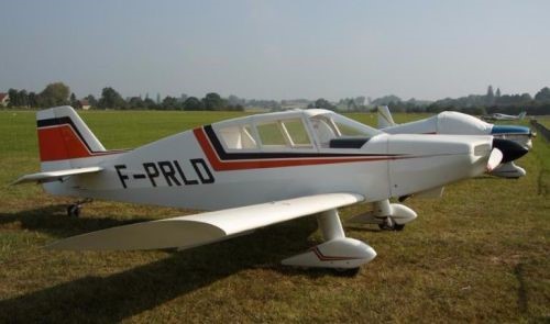
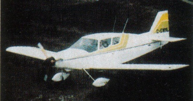
The PGK-1 Hirondelle was designed by Jean Peters, Glenn Gibb and John Kopala. The prototype aircraft C-GWYL (pictured) was six years in development and the designers main objectives were: to design a two-place aircraft that was safe and easy to fly; fast and maneuverable; comfortable and attractive; and easy and economical to build. The aircraft is well suited to first time builders. Engines of 100-125 hp.
Western Aircraft Supplies of Canada markets plans and some components to construct the PGK-1 Hirondelle two-seat monoplane.
Since their success with the first recorded powered flight, the Wright Brothers had patented many of their methods and had sought to enforce their patents through the courts. Most if not all other manufacturers were keen to develop alternative techniques; Pfitzner avoided the Wrights’ method of warping the wings to achieve a lift differential between port and starboard wings by using wing extensions (or ‘compensators’). In his book “Monoplanes and Biplanes: Their Design, Construction and Operation” (1911), Grover Loening wrote “This aeroplane is a distinct departure from all other monoplanes in the placing of the motor, aviator, and rudders, and in the comparatively simple and efficient method of transverse control by sliding surfaces, applied here for the first time.”. The issue of patent protection was sufficiently in the public eye for The New York Times, in its issue of 16 January 1910, to headline Pfitzner’s design as an “Aeroplane Without Patent Drawbacks”. The same article refers to the “Wright suits” and their attempts to “build up their patent fences”; Pfitzner is quoted there as saying that “any one who wants to do so is welcome to use [his] panel invention without cost or fear of injunction”. Pfitzner designed his Flyer as a private project but it was constructed in the Curtiss factory.
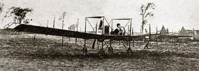
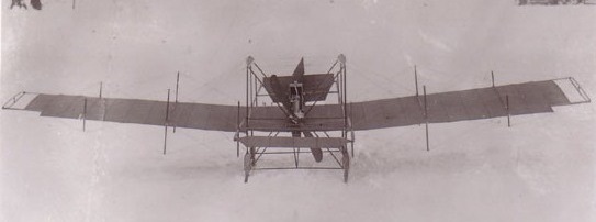
The Pfitzner Flyer was designed in 1909 by Alexander Pfitzner and built by the Curtiss company at Hammondsport, NY, where Pfitzner was employed at the time, a “designer of high-class gasoline motors, transmissions, and gears”. The Flyer was the first monoplane designed, built and flown in the United States. It incorporated several novel features, the most innovative of which was the method of achieving lateral control by means of reciprocating lateral (telescopic) wing extensions, which the pilot controlled via a steering wheel. Also unusual for a monoplane was the use of a pusher configuration, the engine also being mounted behind the pilot.
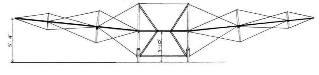
The aircraft consisted of a rectangular cuboid cross-braced central frame, onto which the main monoplane wing, the motor, the forward and rear booms and the ‘undercarriage’ (consisting of one wheel at each of the lower corners) were mounted. Between the upper front and rear posts of the frame were fitted two streamlined fuel tanks (clearly visible in the image above), one on each side of and above the pilot’s seat, with a combined capacity of six gallons (22.7 L.).
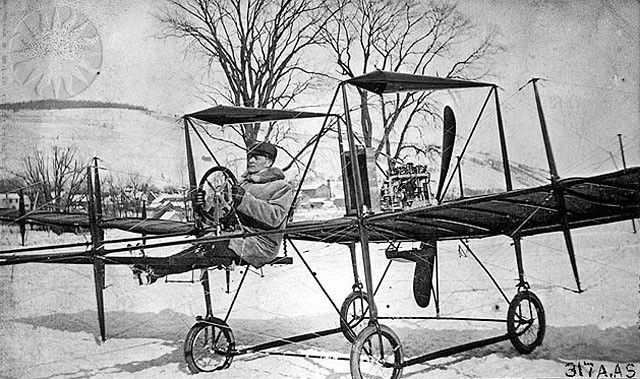
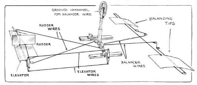
The pilot sat immediately forward of the wing and controlled the aircraft by a combination a movable column and a wheel mounted on that column. Pitch was controlled by fore and aft movement of the column, which, by means of wires, moved the elevator mounted at the forward end of the front boom. Yaw control was effected by twisting the column about its vertical axis (by means of pressure on the steering wheel), which turned the vertical rudder (mounted above the elevator) left or right. Lateral control was achieved by rotating the wheel: When the pilot turned the steering-wheel to port, the linkage retracted the port wingtip, at the same time extending the starboard extension by the same amount. Thus there was no need for a rudder bar (or pedals); the pilot’s feet were not used for controlling the aircraft. Also mounted on the control column was a throttle lever; a button on the wheel enabled “the Bosch high-tension magneto to be switched off for the purpose of switching off the engine”. There was a fixed tail-plane surface with an area of 10.5 sq.ft. (0.98 sq.m.) at the end of the rear boom to provide longitudinal stability.
The span of the main wing, which was set at an angle for incidence of 8°, was 31 ft., with a wingtip extension of 30 in (76 cm) on each wing, providing a constant wingspan of 33 ft. 6 in. (10.21 m). The wing was 6 ft. (1.8 m) wide; the extensible wingtips were 4 ft. 2 in. (1,27 m) wide, each providing a maximum of 10.5 sq. ft. (0.98 sq.m.) wing area. The wing extensions were of the same curvature as the main wing. “The main supporting plane at a 5-deg. dihedral angle consists of two main beams across which are placed spruce ribs. The surface is made of Baldwin vulcanized silk, of jet black colour, tacked to the top of the ribs and laced to the frame. The curvature of the surface is slight and is designed for high speed.” The wing ribs had a camber of 3.75 in. (9.05 cm) over 6 ft (1.8 m).
Each of the wings consists of three detachable sections, each 5 ft. (1.5 m.) long, which are supported by steel sockets and steel cable, the latter forming a symmetrical double king truss with the beams, fore and aft pairs of King posts being situated at the junctions of the sections.
Pfitzner himself, although an inexperienced flyer at the time, conducted initial test flights with his Flyer, the first taking place in early January 1910. Despite the presence of a light covering of snow at the time, it was reported that the Flyer had made a large number of short flights and that it required an average run of 100 ft. (30 m) to get airborne.
The aircraft was not a success, and a disappointed Pfitzner is thought to have committed suicide on 12 July 1910.
Following Pfitzner’s disappearance (and assumed suicide) in July, 1910, Horace K. Kearney took over the aircraft and demonstrated it at aero meets in the succeeding months, including in Boston, before the Pfitzner Flyer became little more than an interesting footnote in the history of aviation.
Powerplant: 1 × Curtiss 4-cyl., 25 hp (19 kW) Propellers: 2-bladed, 6 ft (1.8 m) diameter Wingspan: 33 ft 6 in (10.21 m) (The main span was 31 ft, with extensions providing additional 2 ft. 6 in.) Wing area: 196.5 sq ft (18.26 sq.m) (Area of main wing: 186 sq. ft. (17.3 sq.m.); area of each wingtip extension 10.5 sq. ft.(0.98 sq.m.)) Aspect ratio: 5.17 : 1 Length: 30 ft (9.1 m) Height: 7 ft (2.1 m) Gross weight: 430 lb (195 kg) (Gross weight includes 6 gallons of petrol, 1 gallon of oil and 1.5 gallons of water.) Max takeoff weight: 600 lb (272 kg) Wing loading: 3.2 lb/sq ft (16 kg/sq.m) Maximum speed: 42 mph (68 km/h; 36 kn) Crew: 1