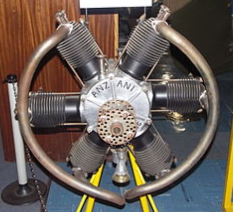
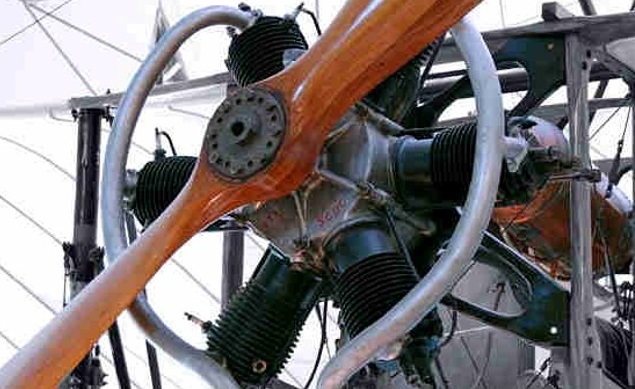
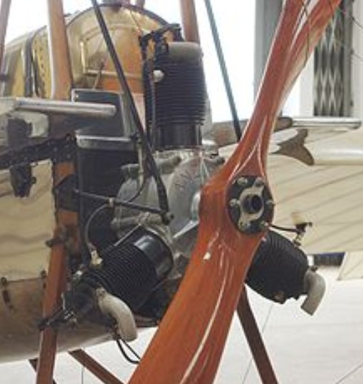
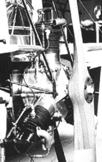
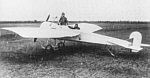
Alessandro Anzani developed the first two-row radial from his earlier 3- cylinder Y engine by merging two onto the same crankshaft with a common crankweb.
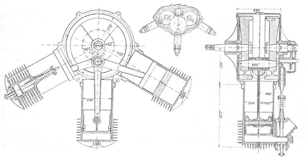
By December 1909 Anzani had a 3-cylinder air-cooled true radial engine running, developed from the earlier 3-cylinder fan configuration engines (semi-radials) that had powered Bleriot across the Channel. By about March 1910 he had completed the first two-row radial engine, a 6-cylinder unit made by merging two 3-cylinder units together, one slightly behind the other and at an angle of 60°. The engine therefore had a lot in common with the early 3-cylinder motors: cylinders were a single iron casting with built-in valve cells and ribs, and pistons were steel with cast-iron rings. The early versions were side-valve engines with automatic (atmospheric pressure opened) inlet valves and exhaust valves mechanically operated via cams in the crankcase. By the end of 1912, as with the smaller engines the exhaust valves were moved to the cylinder heads and operated by push-rods and rockers. The exhaust valves were at the front of the engine, with the fuel inlet manifold at the rear. A prominent pair of 150° exhaust tubes were fitted. Plugs were mounted in the cylinder sides, in the plane of the engine and on the upper side to minimise plug fouling by lubricant.
The crankcase was an aluminium casting and in later models contained a fuel mixing chamber. These later versions also used long bolts to attach the cylinders to the crankcase. The engine used a single, kinked crankweb, coupled to slim but broad connecting rods in order to minimise the axial displacement between the two rows. This was less than in more recent double row radials, the rear face of the front row falling on the centre plane of the back row. The engine was not strictly a radial, as the crankweb geometry slightly offset the centres of the two rows, an arrangement best seen from the back of the engine, where the superimposed inlet tubes and push-rods of the later engine highlight the cylinder centre lines. Such an offset between cylinder centre line and crankshaft is often termed désaxé.
The earliest of the 6-cylinder radials had with a bore of 90 mm and stoke of 120 mm giving a displacement of 4.58 litres (280 cu in) and an output of 34 kW (45 hp) at 1,300 rpm. Its weight was 70 kg (154 lbs). A later version produced 45 kW (60 hp) from 6.33 litres (380 cu in).
Variants:
45 hp (34 kW) Anzani’s first two-row radial developed 34 kW (45 hp) from 4.58 L (230 cu in) displacement.
60 hp (45 kW) Larger cylinders gave 45 kW (60 hp) at 1,300 rpm from 6.23 L (379 cu in ) displacement.
TNCA Aztatl A direct copy of the 60 hp 6-cylinder Anzani, produced in Mexico by TNCA (Talleres Nacionales de Construcciones Aeronáuticas – national aviation workshops).
Applications:
Aeromarine EO Austin Whippet Caudron Type N Farman Scout Perry Beadle T.2 Westland Woodpigeon II
Specifications:
60 hp overhead valve Type: 6-cylinder double row air-cooled radial Bore: 105 mm (4.13 in) Stroke: 120 mm (4.72 in) Displacement: 6.23 litres (379 cu in ) Dry weight: 91 kg (200 lb) Valvetrain: automatic inlet valves, mechanical exhaust valves driven by crankcase can operated pushrods and rockers. One inlet, one exhaust per cylinder Fuel system: carburettor, mixing chamber in crankcase. Oil system: splash lubricated Cooling system: air-cooled, finned cylinders Ignition: single magneto, one plug/cylinder Power output: 45 kW (60 hp) at 1,300 rpm Power-to-weight ratio: 0.49 kW/kg (0.30 hp/lb)
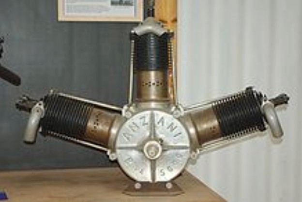
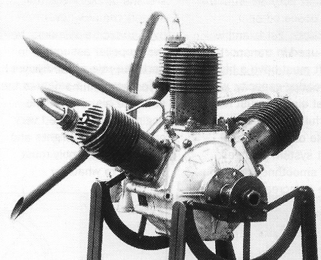
Anzani was aware of the weight cost of the counterweight in the fan configuration and by December 1909 he had a symmetric 120° three-cylinder radial engine running. One example was a 3.1 litre (186 cu in) unit producing 22 kW (30 hp) at 1,300 rpm. Although termed the Y engine after its symmetric cylinder arrangement, it ran in an inverted Y position so that the plugs, mounted on the upper in-plane side of the two lower cylinders were less than 30° below the horizontal and less prone to oiling than one serving a piston at 180° from upright. Radials are smoother running than the less symmetric fan engines as well as lower weight but with the low power available from their three cylinders they had limited applications. They led, however, to Anzani’s two-row radial engines, beginning with the 6-cyl radials, two Ys on a common crankshaft.
Applications: Blériot XI Caproni-Pensuti triplane Deperdussin Type A Sikorsky BIS-2 Perry Beadle T.1
Survivors The restored and flyable Blériot XI, registry number N60094 at Old Rhinebeck Aerodrome uses one of these Anzani three-cylinder “true radial” engines for its straight-line, short distance “hop” flights. Another Blériot XI, with British registration G-AANG, is allowed to fly similar short ‘hops’ at the Shuttleworth Collection. Its original “fan-type” Anzani three-cylinder engine is thought to be the oldest airworthy aircraft engine in the world. A 1910 Deperdussin monoplane that is also restricted to straight ‘hops’ uses a ‘Y’ type Anzani engine.
1912 ‘Y’
Specifications:
Channel flight engine Type: 3-cylinder air-cooled fan Bore: 100 mm (3.94 in) Stroke: 150 mm (5.90 in) Output: 30 hp Displacement: 3.53 litres (216 cu in) Dry weight: 65 kg (143 lb) Valvetrain: Automatic inlet valves, mechanical exhaust valves driven from three separate cams in crankcase. One inlet, one exhaust per cylinder Fuel system: Gronville and Arquembourg carburettor, mixing chamber in crankcase. Oil system: Splash lubrication Cooling system: Air, ribbed cylinders Ignition: Battery ignition, one spark plug per cylinder
Alessandro Anzani began building motorcycle engines in France around 1905. His motors were air-cooled, making them light. His first designs were two-cylinder V-engines, and he rode machines powered by them to records and race success in 1905 and 1906. In the same period he had developed a three-cylinder version, more powerful than the twins. Engines with cylinders arranged radially but only in the upper half-circle were termed fan type, or semi-radials; by about 1910 other manufacturers were building e.g. five-cylinder fan engines, most notably R.E.P. Three-cylinder fans were alternatively known as W or W-3 engines. The appeal of the fan configuration was that, because all the cylinder were above the horizontal there was little danger of the plugs being fouled by the lubricating oil. The disadvantage, particularly for an aircraft engine, was the extra weight required to counterbalance the pistons.
In response to the growing interest in aviation in France after the Wright brothers’ visit in 1908, Anzani produced the first of a series of three-cylinder fan flight engines. The cylinders were each a single iron casting and the one-piece crankcase was aluminium. Pistons were steel with cast rings. In most of these the outer cylinders were at 60° to the central one, though a contemporary diagram shows one, described as the cross channel engine, with a 55° angle. They were all air-cooled side-valve engines; each exhaust valve was controlled from below by a cam in the crankcase. Each was mounted in a cell to the side of the cylinder, with the automatic, atmospheric pressure -driven spring-loaded inlet valve immediately above it, partly to minimise volume and partly to help cool the hot exhaust valve. Most contemporary and pre-1921 sources agree that the bores of these early engines were between 100 and 105 mm (3.93 and 4.13 in), but strokes between 120 and 150 mm (4.72 and 5.90 in) are quoted. Most put the output of these engines at about 18 kW (24 hp) at around 1,400–1,600 rpm.
25 hp
It was an engine of this sort that famously powered Louis Blériot’s Type XI monoplane across La Manche (the English Channel) on 25 July 1909. Contemporary sources differ on its bore, stroke and swept volume. The first description of the successful machine in Flight describes the engine as having dimensions of 100 × 150 mm, or a capacity of 3.53 litres. However, a few months later they printed the engineering drawing of the 55° engine, which has dimensions of 103 x 120 mm marked on it, clearly captioned as “used … in the cross-Channel flight”. If their identification was right, then Bleriot used a 3.00-litre engine. A head-on photograph of the cross-channel aircraft also shows a 55° engine.
Even before the channel flight, Anzani was selling more powerful versions with larger bores: a 120 mm bore, 4.4-litre (269 cu in) variant produced 26 kW (35 hp) and a 135 mm bore, 6.4-litre (390 cu in) engine gave 36 kW (45 hp). These fan engines remained in production until at least 1913,[8] though there were important improvements. The exhaust valve was moved to the cylinder head and operated by rockers via push rods, and a mixing chamber was arranged in the crankcase. The 1913 three-cylinder Anzani fan engine had a cylinder separation of 72°, presumably to lighten the counterbalance. By this stage it had its inlet manifold at the rear of the engine to minimise airflow cooling of the fuel air mixture.
Brownback built a 20hp three-cylinder radial licensed version of the Anzani as the Brownback Tiger Kitten.
Variants:
Anzani 3-cylinder fan engines
10-12 hp (7.5-9 kW) Bore x Stroke: 3.35 in × 3.35 in (85 mm × 85 mm) Capacity: 88.5 cu in (1.45 lt)
12-15 hp (9-11 kW) Bore x Stroke: 3.35 in × 3.94 in (85 mm × 100 mm) Capacity: 104 cu in (1.70 lt)
25-30 hp (19-23 kW) Bore x Stroke: 4.13 in × 5.12 in (105 mm × 130 mm) Capacity: 206 cu in (3.38 lt)
40-45 hp (30-34 kW) Bore x Stroke: 5.32 in × 5.92 in (135 mm × 150 mm) Capacity: 393 cu in (6.44 lt)
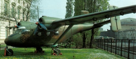
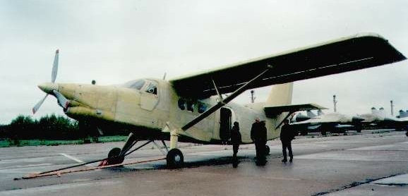
The Antonov An-181 (or product 181, Ukrainian: Виріб 181, Russian: изделие 181) project was terminated because of the lack of funds due to the collapse of the Soviet Union. An interesting feature of the plane is its unusual arc-shaped wing, a so-called Channel wing. The aircraft has two seats next to each other, a conventional fixed landing gear, a V-tailplane, and high-wing equipped with a channel wing in the area of the propellers. Power from the engine is delivered by means of drive shafts and deflection gearboxes to the two-blade propellers. The aircraft received the registration СССР-190101 and is exhibited in the State Museum of Aviation of Ukraine. Willard Ray Custer had previously built aeroplanes with the same wing concept in the USA.
Crew: 2 people Length: 7,31 m Wingspan: 7,3 m Height: 2,5 m Wing area: 7 m² Normal take-off weight: 820 kg Maximum take-off weight: 900 kg Engine: AP LOM M-337A, 6 cylinders, 103 kW Propeller diameter: 1.5 m Maximum speed: 225 km / h Practical range: 530 km Service height: 4200 m Starting distance: 70 m Landing distance: 80 m
The T-2M was developed by the Antonov Design Bureau at the end of the Cold War when it became necessary to explore civil markets for aircraft, including microlights for club flying. Aside from production for recreational purposes, the T-2M was also designed for use by the Russian Special Forces for use on infiltration missions, and as such incorporated a sophisticated wing folding mechanism at their request.
The T-2M features a cable-braced hang glider-style high-wing, weight-shift controls, a two-seats-in-side-by-side configuration open cockpit, tricycle landing gear and a single engine in pusher configuration. The aircraft is made from tubing, with its wing covered in Dacron sailcloth. Its 163 sq ft (15.1 m2) area wing is supported by a single tube-type kingpost and uses an “A” frame control bar. The standard engine supplied was the 64 hp (48 kW) Rotax 582 twin-cylinder, two-stroke, liquid-cooled powerplant. The smaller 50 hp (37 kW) Rotax 503 and the four-stroke 80 hp (60 kW) Rotax 912 were also supplied.
The T-2M introduced two features not found on western trikes. It has side-by-side seating, which offers advantages in flight training and also has a large single piece leaf spring main landing gear, which is simple, light, low drag and eliminates many of the large number of parts that other designs use. The aircraft can be operated on wheels, skis and floats. An agricultural aircraft aerial application package is also available.
The T-2M was sold in North America and a dealer, UK-Air, was based in Mississauga, Ontario, Canada. It sold for US$18,500 in 2000.
T-2M Engine: 1 × Rotax 582, 48 kW (64 hp) Wing area: 15.1 m2 (163 sq ft) Empty weight: 170 kg (374 lb) Gross weight: 352 kg (775 lb) Fuel capacity: 26 litres (5.7 imp gal; 6.9 US gal) Cruise speed: 89 km/h (55 mph, 48 kn) Stall speed: 45 km/h (28 mph, 24 kn) Rate of climb: 5.1 m/s (1,000 ft/min) Crew: one Capacity: one passenger
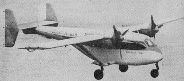
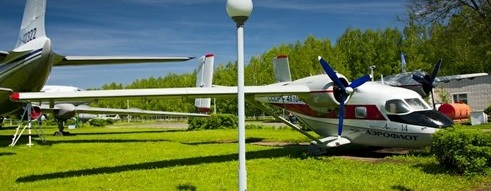
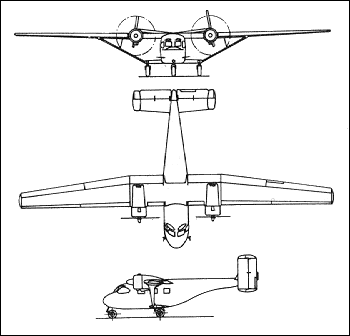
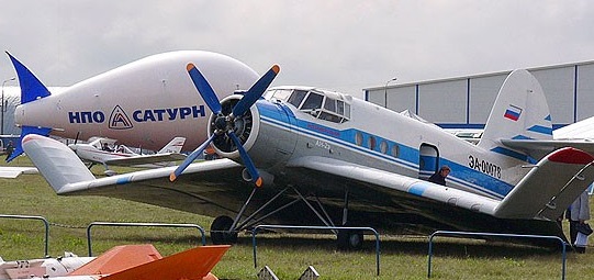
The Antonov designed An 14A Ptchelka (Bee), first flown on March 15, 1958, entered service with Aeroflot as a successor to the An 2 biplane, after five and a half years of flight testing and modification. Production began both for Aeroflot and the Soviet armed forces at the Progress Plant at Arsenyev in 1965 and by the mid-1970s well over 300 aircraft had been delivered. The military version, first seen at the Domodedovo air display in 1967, appeared not to differ from the civilian passenger version externally.
The An-14A featured an increase in wing span and the introduction of 300 hp AI 14RF engines.
The An-14 was a light transport used for agricultural and air ambulance duties which eventually evolved into the 19-seat An-28, and was produced by PZL Mielec in Poland until at least 1991. It entered service with only one division of Aeroflot, in Khazakistan.
Carrying the NATO reporting name Clod, An-14 were also in service with the air forces of Bulgaria, the German Democratic Republic and Guinea.
An-14A Engine: 2 x AI-14RF, 220 kW Wingspan: 21.4 m / 70 ft 3 in Length: 11.0 m / 36 ft 1 in Height: 4.2 m / 13 ft 9 in Wing area: 43.5 sq.m / 468.23 sq ft Take-off weight: 4410 kg / 9722 lb Empty weight: 2310 kg / 5093 lb Payload: 1,323 lb (600 kg) Max. speed: 350 km/h / 217 mph Cruise speed: 106 112 mph (170.5 180 km/h) Ceiling: 5000 m / 16400 ft Range: 1550 km / 963 miles Range w/max.fuel: 780 km / 485 miles Range 1,235 lb (560 kg) payload, 1 hr res: 453 mls (730 km). Range w/max.payload: 300 km / 186 miles ROC: 1,020 fpm (5.18 m/sec) SE ROC: 300 ft/min (1.5 m/sec) Take off distance: 295 ft (90 m) fully loaded Landing distance: 361 ft (110 m). Crew: 1 Passengers: 7-9
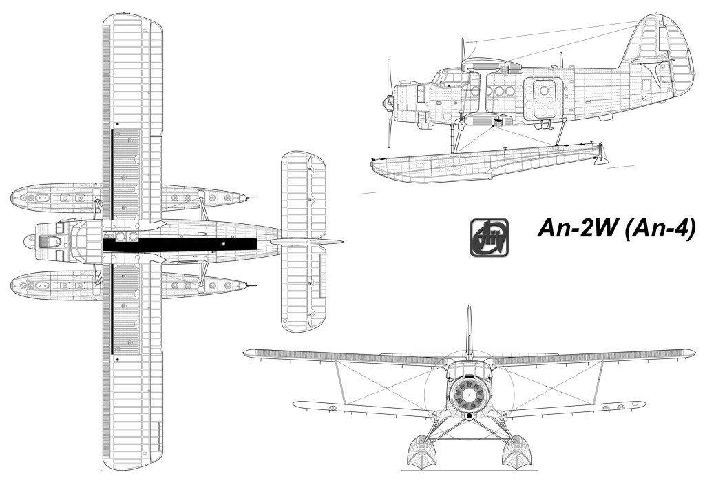
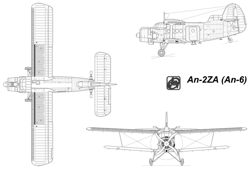
The An-2ZA variant of the An-2 (design bureau designation An-4) is intended specially for high-altitude meteorological research. The An-4 has a glazed position immediately in front of the tail fin for an observer. The ZA suffix standing for Zondirovanie Atmosfery, translatable as ‘air sampling’. The An-4 is able to maintain power up to 10,000m by the ASh-62IR engine has a TK supercharger mounted on the starboard side of the cowling. The spinner of the An-2 standard model is deleted to aid engine cooling, and the original ailerons have been replaced by an unslotted variety.
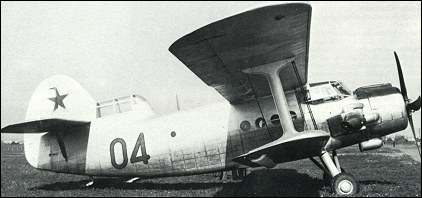
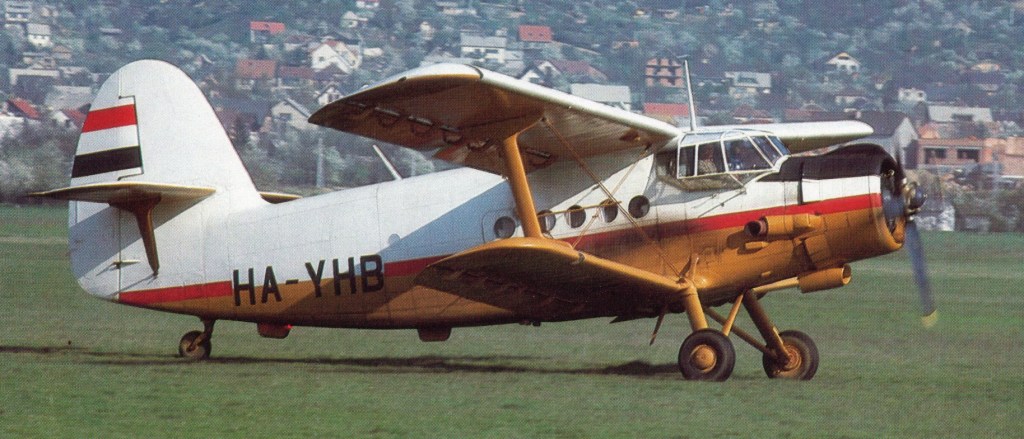
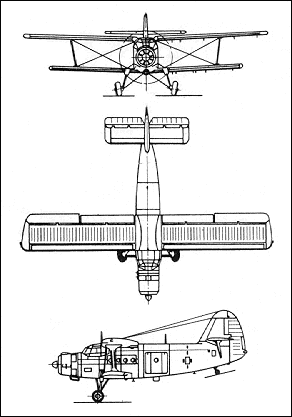
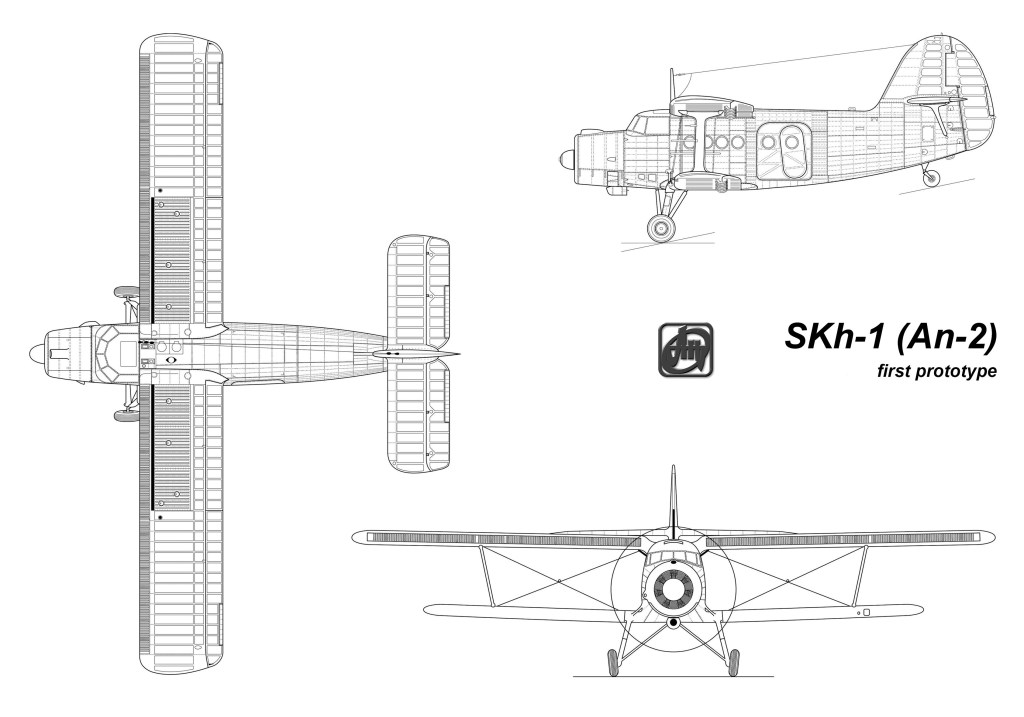
Designed originally for agricultural duties two prototypes of what became the An-2 were designated SKh-1 and the first example made its first flight on August 31, 1947. The type was developed by OKB-153 (Design Bureau 153) which was later named after Oleg Antonov. The prototypes had a 630-hp Shvetsov ASh-61, and ASh-62 respectively, radial engine with the latter being selected for production aircraft. With an all metal fuselage and fabric wings aft of the main spar, the aircraft can carry a crew of 2 plus 14 passengers. NATO code name ‘Colt’ and is designated in US DoD nomenclature as the “Type 22”.
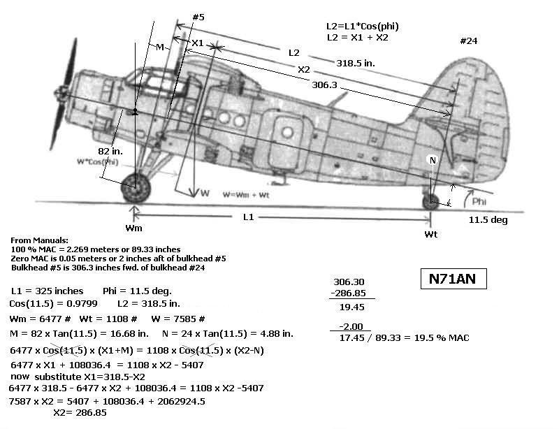
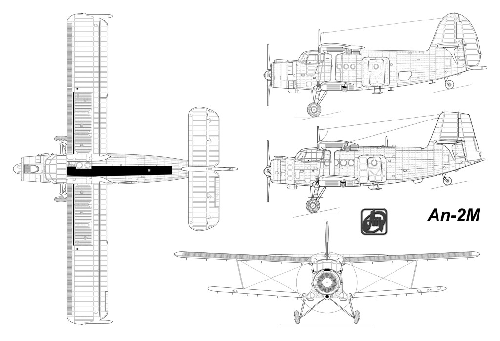
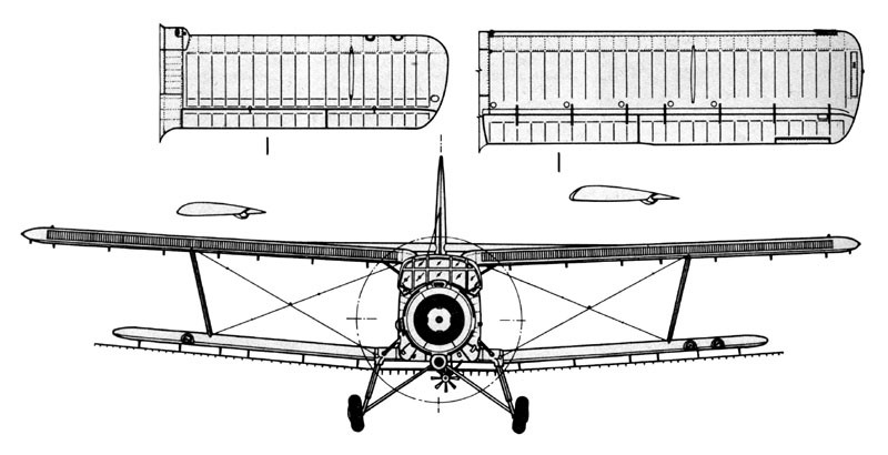
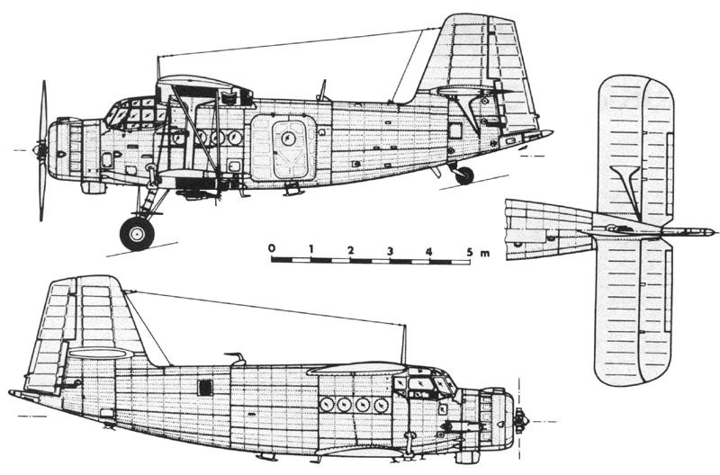
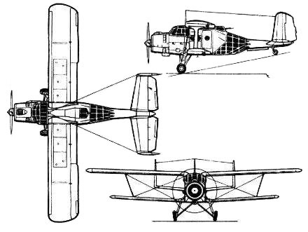
Externally, the An-2 engine – powering a four-bladed propeller – is held in the extreme forward of the fuselage with the cockpit directly aft. The cockpit is heavily glazed and observation port windows can be seen along the fuselage sides. Wings are of an unequal span single bay biplane design, all metal construction, with fabric covering. Each wing is connected via a single large vertical strut making up a single wing bay and each wing has dihedral. The wings have full length automatic leading edge slats and ailerons droop with flap actuation to provide great STOL performance. Fuselage is of all-metal stressed skin semi-monocoque construction. The fuselage tapers slightly into the empennage which has a single large, smooth-edge vertical tail fin and stabilizers mounted to either tail fin side. Tail is a braced all metal structure with fabric covering. Wing area is 770 square feet total. Ailerons, rudder, and elevators are all manually controlled with pushrods and cables. Flaps and trim electrically operated.
The landing gear is of conventional configuration (tail wheel design) with split axle, long stroke oleo shock absorbers on the main mounts and a fully castoring and self centering tail wheel. The main landing gear legs feature wheel bogies angled inwards with each leg braced at two points along the underside of the fuselage. Brakes are pneumatically operated. Normally two pilots, but may be flown single pilot when no passengers are aboard.
The compressed air system has an 8 litre (490 cu.in) air cylinder at 49 bars (711 PSI) maintained by an engine driven AK-50M compressor and AD-50 relief valve. A pressure gauge is on pilot’s left hand console. A pressure reducer supplies 10 bars (145 PSI) for the main brakes. The Air Pressure is required for the pneumatic main wheel brakes, but can be used to charge the landing gear shock absorbing oleo-pneumatic struts when dry nitrogen is not available. A fitting is also available to fill the tires from this system. The 8 litre air cylinder can also be charged from appropriate ground support equipment.
The electrical system has a 24 VDC battery with engine driven generator to maintain charge. A Voltmeter and Ammeter are on the Instrument Panel. The 28 VDC generator requires at least 900-1000 RPM to kick in. 36 Volt 3 phase 400hz AC power, supplied by two convertors, is used to power the Russian Gyroscopic compass, Artificial Horizon and ADF.
Nine fire detectors are located throughout the engine compartment. If the Fire Warning Lamp light, the CO2 system can be activated by breaking the safety seal and pushing the button. The CO2 bottle has an electrically activated pyro-technic cartridge to release the CO2 into the collector. Portable CO2 Fire Extinguishers are normally installed in the cockpit and cabin as well.
The Oil System consists of a 125 litre (33 gal) max permitted 22 gal tank, suction pump and an external oil cooler with electrically controlled shutters. They use Aeroshell 100 Oil.
Accommodations are generally made for a crew of one pilot and cabin seating can hold an additional 12 passengers.
Almost 3600 An-2 were built at Kiev, ending in mid-1960s after limited manufacture of specialised agricultural An-2M. Production was transferred to PZL Mielec, Poland.
The An-2R developed and built by WSK-PZL in Poland was a special agricultar model. Introduced in 1964, it carried a fiberglass container for 1960 litre pesticides or 1350 kg fertilisers.
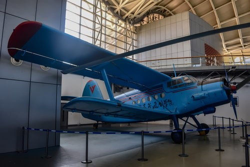
China acquired licence and has built Yunshuji-5 (Y-5) versions from 1957.China has produced many versions of the An-2 beginning with the Fong Shou-2 (“Harvester-2”). This was the first An-2 built to agricultural specifications. The Nanchang Y-5 is a transport version since taken over in production by Harbin with 727 examples delivered. Nanchang Y-5II was an agricultural form seeing production number 229. Shijiazhuang Y-5A was a light passenger model based on the An-2T and produced in 114 examples. The agricultural derivative became the Shijiazhuang Y-5B based on the An-2 SKh. The PLAAF makes use of the Shijiazhuang Y-5B(T) para-drop model. The Nanchang Y-5C is an amphibious version of the Y-5A while the Nanchang Y-5D is a bomber crew trainer. The Nanchang Y-5K became a VIP passenger transport seating five.
Y-5
By 1991 over 18.000 of the different types were built in the Ukraine (5000), Poland (12000) and China (1000). In 1994 the Polish manufacturer of the An-2, Meliec, produced a version which conformed to the US FAR 23 requirements.
The Antonov An-2 has seen combat action. It was debuted during the Korean War (1950-1953) and later in the Vietnam War – the latter by the North Vietnamese. Some An-2’s were converted from their traditional crop dusting roles to become make-shift bombers in the Croatian War of Independence (1991).
Notable operators of the An-2 have included Afghanistan, China, Cuba, East Germany (and Germany proper), Egypt, Georgia, Hungary, Iraq, Laos, Lithuania, Macedonia, North Yemen, North Korea, Poland, South Korea, Romania, Russia, Serbia, Somalia, Sudan, Syria, Turkey, Ukraine, Vietnam, Yemen and Yugoslavia.
The An-3 was originally considered as a turboprop development of An-2, but was offered as a midlife upgrade of the An-2 to have a turboprop engine and other improvements (first flown 1980).
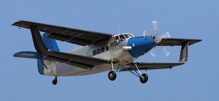
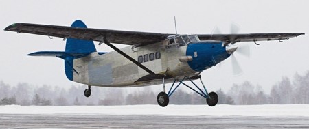
Another organization working on a “better” An-2 is SibNIA (Siberian Aeronautical Research Institute) in Novosibirsk, Russia. In this version, the An-2MS (An-2MC in Russian) and later usually referred to as the TVS-2MS), the radial engine was replaced by an 1,100 hp Honeywell TPE331-12UHR turbine, driving a five-bladed Hartzell propeller. The first An-2MS/TVS-2MS was first flown on September 5, 2011 and by 2015 well over fifteen examples had been delivered by SibNIA and Rusaviaprom JSC, all built, from existing An-2 airframes retaining the An-2 wings and tail feathers.
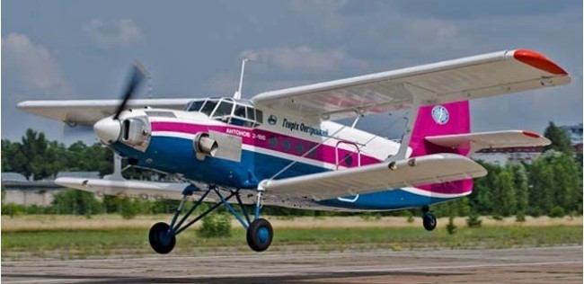
An-2-100
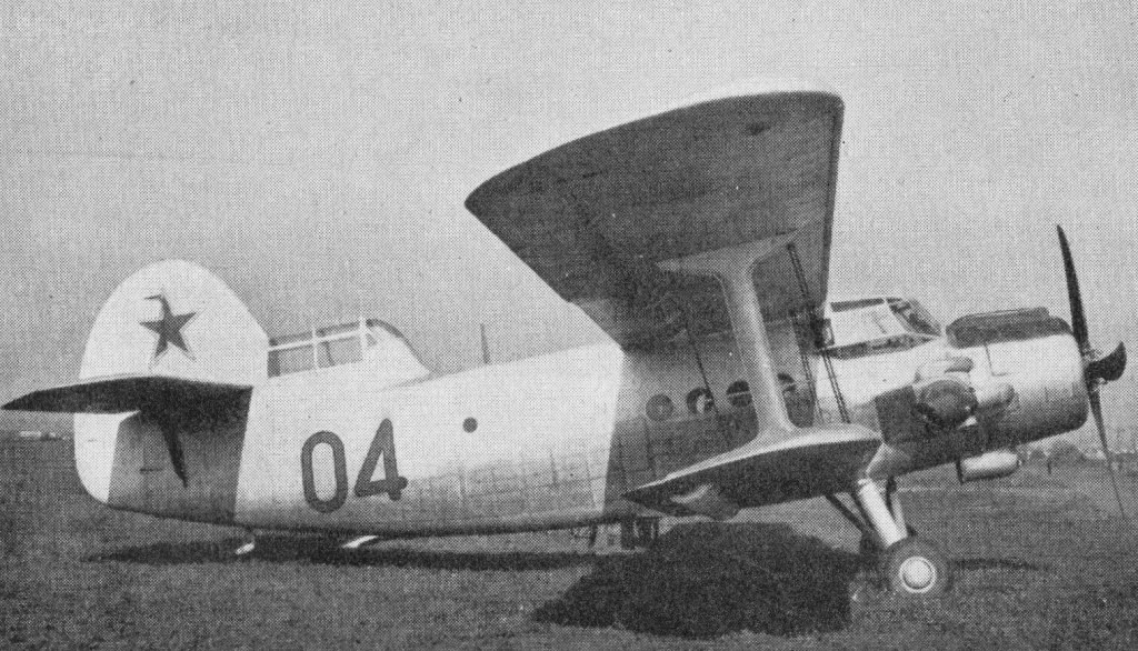
An-2 04 was modified for meteorological research by the addition of an observation cockpit in front of the fin, and a turbo-supercharger on its Ash-621R radial engine.
On 19 July 1954 it established an FAI altitude record for its class of 11,248 m (36,880 ft).
There was even a ground effect version, the An-2e WIG.
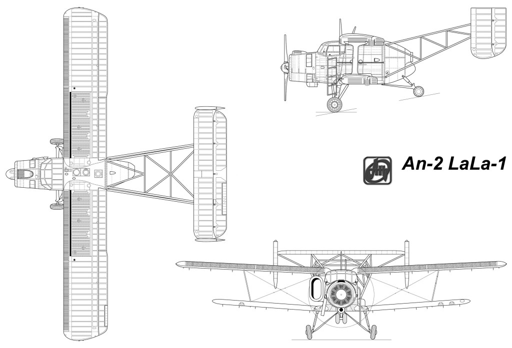
There have been various attempts to modernise the AN-2 over the years;
Antonov An-2 (Colt) Engines: 1 x Shvetsov ASh-62IR 9-cylinder supercharged radial, 1,000 horsepower. Length: 40.68ft (12.4m) Wingspan: 59.71ft (18.20m) Height: 13.45ft (4.10m) Empty Weight: 7,275lbs (3,300kg) Maximum Take-Off Weight: 12,125lbs (5,500kg) Maximum Speed: 160mph (258kmh; 139kts) Cruise: 100-110 kt. Maximum Range: 525miles (845km) Rate-of-Climb: 700ft/min (213m/min) T/O roll: 220 ft. Service Ceiling: 14,750 ft (4,500m) Accommodation: 2 + 12
Engine: Shvetsov ASz-62 IR, 1000 hp max Propeller: 4 blade AW-2 Wing Span: 59 ft 8 in / 18.18 m or 14.2 m / 46 ft 7 in Length: 41 ft 9 in / 12.74 m Height: 4.1 m / 13 ft 5 in Total Wing Area: 256.6 sq.ft Upper wing area: 156.2 sq.ft Lower wing area: 100.4 sq.ft Empty weight: 7,600 lb Max Take Off weight: 12,125 lb / 5500.0 kg Max Landing weight: 11,574 lb Max fuel: 2,000 lb / 312 USG Oil Qty: 22 Gallons Max / 13 Gallons minimum to 18 Gallons normal Useful load max fuel: 2,525 lb Useful load half fuel: 3500 lbs VNE: 162 kt VFE: 70 kt Best Glide: 65 kt Maximum Speed: 139kt / 160 mph / 258 km/h Economy Cruise: 100kt / 115 mph Minimum Speed: 49kt / 56 mph Take-Off Speed: 43kt / 50 mph (15 degrees of flap) Landing Speed: 46kt / 53mph (30 degrees of flap) Stall Speed: 35-40kt (controlled descents are possible at 25kt / 30mph) Typical SL Take-Off to 50 ft: 1600 ft Minimum SL Take-Off Run: 560 ft Typical SL Landing distance 50 ft: 1400 ft Normal Range: 485nm / 900 km with 45 min. res Max Range: 550nm / 6 hours endurance Max SL Rate of Climb: 680 fpm Time to 14,425 ft: 30 min Service ceiling: 16404 ft / 5000 m Ceiling: 14,425 ft with 1,100 lb cargo Cross wind component: 8 kt with full flaps Max wind speed for taxy: 20 kt Cargo compartment: 13.5 ft long x 5 ft wide x 5.9 ft high Cargo compartment capacity: 398.25 cu.ft Cargo door opening: 4.5 ft wide x 5 ft high Crew: 2 + 16
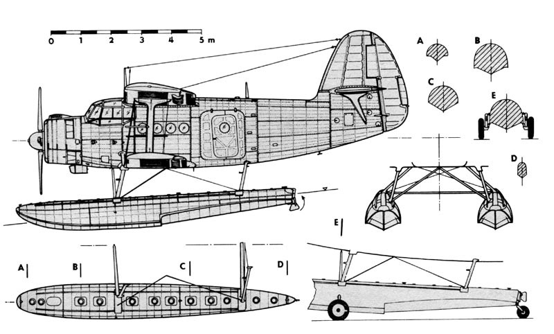
An-2V floatplane Wingspan: 59 ft 7.5 in Wing area: 769.6 sq.ft Max speed: 153 mph TO dist: 260-330 ft Landing dist: 195-260 ft Min water depth: 32 in Max wave height: 20 in
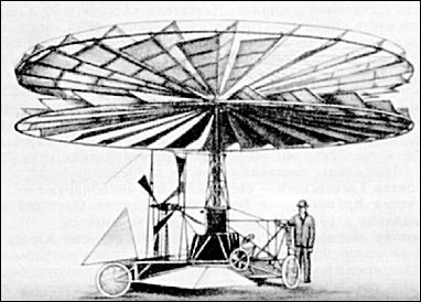
Built by the Russian military engineer K. A. Antonov [К. А. Антонов], in development at St. Petersburg from 1907-1911. The essence of the machine was that it rose vertically by the use of the counter-rotating rotors and after gaining enough height it was flown horizontally by the propeller. In 1907 military engineer K.A.Antonov applied for, and in 1912 obtained a patent for his Helicoplane.
The whole system was driven by one 25 hp engine, so a complex system of cogwheels and rods was probably necessary to work the rotors and propeller. As the Helicoplane – according to reports – did not fly, it may be presumed that it was too heavy. As he was a military engineer it can be assumed that there was some form of financial backing or other help received from the Russian government.
The helicoplane was built and tested in St.Petersburg during 1910. Despite all systems working as expected, the Helicoplane failed to takeoff.
Antonov was otherwise prominent in Russian aviation as he participated in the design and building of the 6,900 m³ dirigible “Krechet” in 1910.