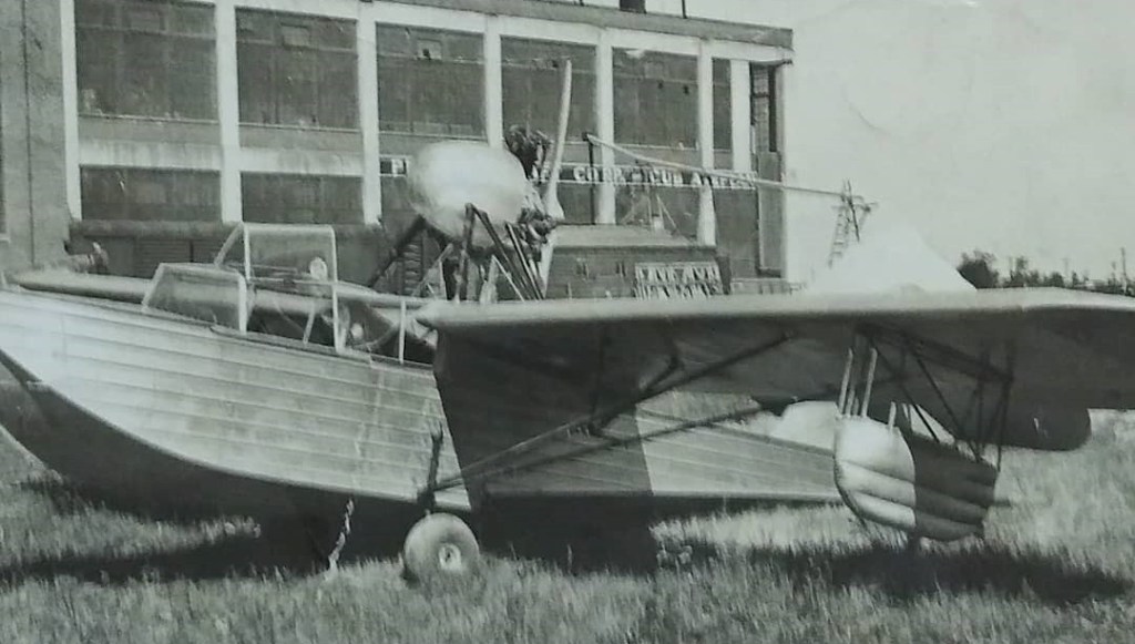
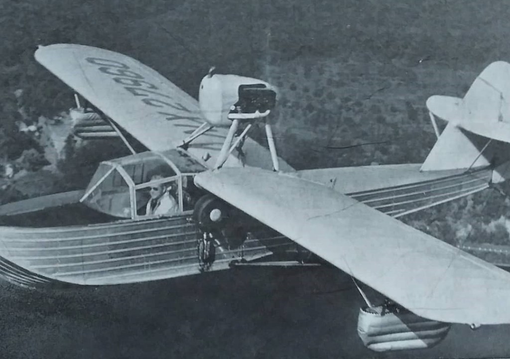
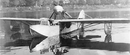
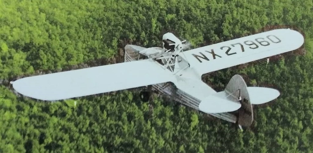
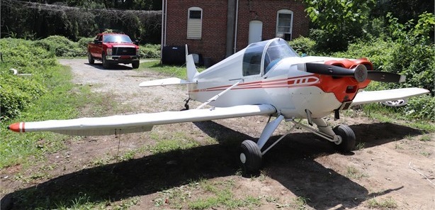
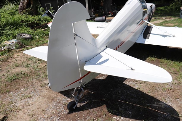
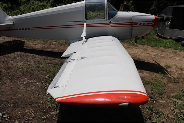
This is the Duck Amphibian that was created by Ray Applegate in 1937. He brought the Amphibian to Lock Haven in 1939 to see if Piper would be interested in manufacturing it. However the project was eventually dropped. Mainly due to WWII.
Designed by Ray Applegate, the 1937 amphibian, registered NX17866, used a Piper J-3 wing and was priced at $2,500±.
Applegate Duck NX17866
Only one was built, the name changed to Applegate 3 Clipper in 1947.
Walter Jamouneau recalled ‘The airplane didn’t fly very well. It made a lot of noise but didn’t go anywhere. The drag was spectacular”.
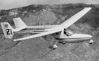
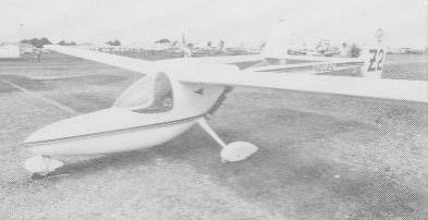
The Zia was originally conceived as a tailless motor glider and transformed by Oshkosh 1983 into the twin-boom pusher.
George Applebay entered the ultralight world with a very soaring oriented design, the Zia, whose control system consists of tip rudders, angled so that they work in roll as well as yaw and controlled by stick and pedals through a mixer, and a slotted flap occupying 25% of the canard surface, which provides pitch control. Glidepath control is by flaps which extend to 45 degs. The tricycle undercarriage has a steerable nosewheel and the braked main wheels are suspended on glass fibre struts reinforced with Kevlar. He designed the Zia according to the JAR22 standard, using composite construction in the main but with Dacron wing covering. Single seat single engined mid wing monoplane with conventional three axis control. Wing has swept forward leading and trailing edges, and tapering chord; no tail, canard wing. Pitch control by flaps on canard; yaw/roll control by angled tip rudders; control inputs through stick for pitch/yaw/roll and pedals for yaw/roll. Cantilever wing; wing profile; double surface. Undercarriage has three wheels in tricycle formation; suspension on nosewheel and glass fibre/Kevlar suspension on main wheels. Flush right go right nosewheel steering connected to yaw control. Brakes on main wheels. Composite construction fuselage, totally enclosed. Engine mounted at wing height driving pusher propeller. The engine is started by a pull rope either on the ground or for air starting.
Engine: Robin EC25PS, 18 hp. Power per unit area 0.14 hp/sq.ft, 1.6 hp/sq.m. Fuel capacity 4.0 US gal, 3.3 Imp gal, 15.0 litre. Length overall 13.1ft, 4.00m. Wing span 43.3ft, 13.20m. Total wing area 125sq.ft, 11.6sq.m. Empty weight 209 lb, 95kg. Max take off weight 452 lb, 205kg. Payload 243 lb, 110kg. Max wing loading 3.62 lb/sq.ft, 17.7 kg/sq.m. Max power loading 25.l lb/hp, 11.4kg/hp. Never exceed speed 81 mph, 130kph. Cruising speed 59mph, 95 kph. Stalling speed 28 mph, 45 kph. Best glide ratio with power off 27/1 at 42 mph, 67 kph. No. of Seats: 1
The Apollo Fox is built according to the BCAR Section S constuction norm. The aircraft has welded steel alloy tube fuselage covered with ceconite fabric. The wings are made of aluminium alloy both spars and ribs and then covered with ceconite. Wing can be folded backwards. One pilot can do it within 10 minutes. The landing gears are aluminium plate sheet as year suspension. Wheels are equipped with hidraulic disc or mechanical drum brakes. Available tail or nose wheel configurations. Engine opts: Rotax 582 UL Mod 99 (65Hp) Rotax 912UL (80 Hp) Rotax 912 ULS (100 Hp) Jabiru 2200 (80Hp) Subaru EA 81 (100 Hp). Stall: 35 kt / 40 mph / 64 kmh Cruise: 81 kt / 93 mph / 150 kmh VNE: 97 kt / 112 mph / 180 kmh Empty Weight: 274 kg / 604 lbs MTOW Weight: 450 kg / 992 lbs Take-off distance (50ft obstacle): 460 ft / 140 m Landing distance (50ft obstacle): 660 ft / 200 m
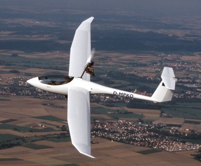
The Apis series includes both a 13- and 15-meter sailplane, is a combination of composite construction and old world craftsmanship. The Apis is intended for the sport flyer, but still holds several world records. They offer a forward-hinged canopy, automatic control hookups, in-flight adjustable rudder pedals, full-span flaperons, blended winglets, and Schempp-Hirth type airbrakes. They also make the Apis M, a 15-meter motorglider.
The Apis 2 is built with CFRP technology with 15 m span and T-tail. The wings are a multi trapezoid with raising tips. Aileron and flaps are interconnected (flaperons) and standard SH airbrakes give short landing approaches. The spars are connected with two bolts in tongue/tongue technique. Rigging is straight forward and can be easily accomplished by one person. The glider fits in a standard sailplane trailer. The large canopy opens to the side and allows easy access to the ergonomic and roomy cockpit. The Apis 2 includes a parachute rescue system. Wearing a pilots parachute is therefore not necessary and allows tall pilots to fit in the Apis 2. The Apis 2 has a large canopy that opens to the side. The back-board can be adjusted continuously, the rudder pedals have some detents, and both can be readjusted during flight. The electric starter button and the throttle are located in the arm rest on the left side. The panel offers space for six instruments with 57 mm diameter in addition to the ECU indicator. One of these six can be replaced by a 80-mm-instrument alternatively. The battery fits into the quick-release rack in the fuselages nose. It energises both the ECU and the instruments. The Apis 2 cockpit is made up of a double hull. The lightweight hollow section frame of the canopy offers a maximum stiffness in this area. The Apis 2 takes off under its own power as a self launch glider. Despite the fixed tailwheel it is easy to control on the ground. Two aerodynamic tip wheels help eliminate the need for a wing runner. The Apis 2 has a fixed gear with a wheel brake on the 4″ wheel. After a short roll only climb rate is about 2.5 m/s (4.8 kt) at a speed of 80 to 85 km/h (45 kt). After about 150 m (500 ft) it will be airborne and it takes about 290 m (950 ft) over the 50 ft obstacle. There is almost no trim change flying under engine or in gliding mode or while extending or retracting the engine. The camber changing flaps with a neutral trim will give you a speed range of 80 km/h (43 kt) at +9° to 160 km/h (86 kt) at -6°. Thermal speed is about 80 km/h (43 kt) and minimum sink is 0.6 m/s (115 fpm). Best glide speed is 95 km/h (52 kt) which will give you a L/D of 39. Landing approach is at 90 km/h (48 kt) with positive flaps. The highly efficient airbrakes allow safe and steep approaches into short airfields. The Apis 2 can be landed with retracted or with extended engine. The Apis 2 powerplant is an aircooled single cylinder Hirth F33 with intake and exhaust silencer. It generates 27 hp from 303 cc. The 148 cm ground adjustable carbon fibre propeller has been developed by Martin Wezel specially for the Apis 2. The noise level of the Apis 2 is at 57.7 db(A). The powerplant is retractable. The process is controlled by ECU (Engine Control Unit) an instrument by TL elektronic. The extension of the powerplant is started by switching on the main switch, then the ignition. The ECU then takes over the process and the pilot can start the engine with the starter button. It is not necessary to manually control fuel valve or a choke lever. The ECU is optimizing the engine according to the temperature. During the retraction procedure for the powerplant the ECU is activating the propeller stop as soon as the RPM allows. Then the ECU is controlling the full procedure until the engine is completely stowed away. The whole process takes about 20 seconds. German certification in the Ultralight category was issued on 4 September 2003.
Apis 2 Span: 15 m Wing area: 12.4 sq.m Aspect ratio: 18.2 Length overall: 6.5 m Empty weight: from 210 kg Max. gross weight: 320 kg Max. load factor: +5.3 / -3.3 g L/D: 39 at 95 km/h (52 kt) Min. sink rate: 0.6 m/s at 80 km/h (43 kt) Flap settings: +9°, +5°, 0°, -3°, -6° Stall: 35 kt / 40 mph / 65 kmh Cruise: 81 kt / 93 mph / 150 kmh VNE: 200 km/h (108 kt) Engine: Hirth F 33 B, 27 PS / 19.3 kW Carburetor: Mikuni membrane carburetor Drive: Poly-V-belt 1:2.5 Propeller: Wezel 2-blade CFRPØ 1.48 m Fueltank: 14 liter Fuel consumption while climbing: 9 l/h Noise level: 57.7 dB(A)
The original design, the Pouchel, was based upon the 1930s Henri Mignet-designed Mignet Pou-du-Ciel (Flying Flea), but constructed using three commercial household aluminium ladders to save construction time, cost and weight. The aircraft first flew on 14 March 1999 and 120 sets of plans were quickly sold.
When the ladder manufacturer no longer wanted to sell ladders for aircraft construction, due to liability concerns, Dalby redesigned the aircraft to use aeronautical rectangular aluminium tubing instead, which resulted in a lighter and cheaper aircraft, the Pouchel II.
Pouchel II
The Pouchel II replaced the original APEV Pouchel in production. The original Pouchel was constructed using three commercially available aluminium ladders, hence APEV is the Association pour la Promotion des Echelles Volantes, or in English, Association for the Promotion of Flying Ladders. Later the ladder manufacturer grew concerned about liability and refused to supply any more ladders. The Pouchel was then re-designed to use aeronautical rectangular aluminium tubing in place of the original ladders and the new aircraft was designated the Pouchel II. The Pouchel series are all derivatives of the classic 1930s Henri Mignet-designed Mignet Pou-du-Ciel (Flying Flea).
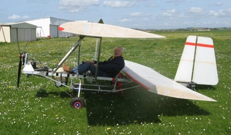
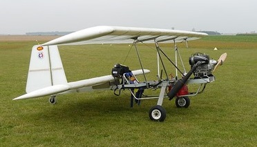
The Pouchel II features a cantilever rear wing with a strut-braced parasol front wing, a single-seat open cockpit without a windshield, fixed conventional landing gear and a single engine in tractor configuration. The aircraft is made from bolted-together aluminium tubing, with its flying surfaces covered in Dacron sailcloth. Its 6 m (19.7 ft) span front wing and 4 m (13.1 ft) span rear have a combined area of 12 m2 (130 sq ft) and both employ NACA 23112 airfoils. The prototype used a 40 hp (30 kW) Rotax 447 two-stroke powerplant, but the 35 hp (26 kW) Rotax 377 is also recommended. The 28 hp (21 kW) Hirth F-33 has also been fitted.
The Pouchel II sold for €4,000 in 2003. The APEV Pouchel II was supplied as plans or as a kit for amateur construction, but is no longer available. It has been replaced in production by the APEV Pouchel Light.
The Pouchel II was further refined into the Pouchel Light and an electric powered version, the Pouchelec.
Supplied as plans or as a kit for amateur construction, the Pouchel Classic is derived from the APEV Pouchel and features a cantilever rear wing and a strut-braced front parasol wing, a single-seat open cockpit, fixed conventional landing gear and a single engine in tractor configuration.
The Pouchel Classic differs from the earlier Pouchel in that it has a newly designed wooden fuselage to replace the aluminum ladder and rectangular tube design of the Pouchel and the Pouchel II. The Pouchel Classic’s fuselage is also longer. Its 6 m (19.7 ft) span front wing and 4 m (13.1 ft) span rear wing have a combined area of 12 m2 (130 sq ft) and employ NACA 23112 airfoils. Flying surfaces are covered in Dacron sailcloth. Standard engines recommended are the 35 hp (26 kW) Rotax 377 or the 40 hp (30 kW) Rotax 447 two-stroke powerplants. The Pouchel Classic kit sold for €5,000 in 2011.
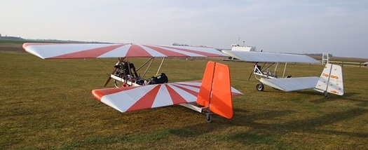
A gasoline powered Pouchel (foreground) and a Pouchelec (background)
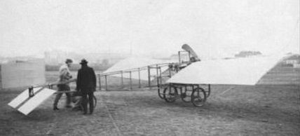
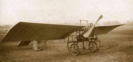
Anzani built his plane in 1909, the same year he took up flying a Voisin type machine. The Anzani had a span of 8 meters and was powered by a 3 cylinder Anzani engine with a belt drive to the propeller. The project had limited success and was financed by de Mas.
By 1912 Anzani had built the world’s first two-row radial engine, the ten-cylinder Anzani 10, which came in two sizes, the bigger 12.1-litre one producing 100-110 hp. By the middle of 1913 the company had a double version with four rows of five cylinders, rated at 200 hp called the Anzani 20. This was displayed at the Paris show of that year and had much in common with the ten-cylinder engine. An air-cooled motor, its cylinders were made of cast iron, with integral cooling fins. The pistons and their rings were also cast iron, machined inside and out. Conical seats for the inlet and exhaust valves were ground into the flat cylinder head, the nickel steel valves being of the poppet type. The automatic, atmospheric pressure operated inlet vales of the earliest Anzani engines were retained, but, as in other later Anzanis the exhaust valves were push-rod and rocker operated.
The aluminium crankcase was made in three parts, a drum and two end plates plates, bolted together and the cylinders were fixed to it by long bolts from the cylinder heads which joined other bolts through the crankcase. As with Anzani’s other multi-row engines there was significant overlap between the rows in order to bring the big ends close together along the crankshaft. The hollow crankshaft was of nickel steel and mounted in ball bearings. It had a pair of crankpins set 180° apart, one for each group of ten cylinders front and back. Lubricating oil was pumped through the crankshaft and then distributed by centrifugal force; there were two oil pumps, one for each “half” of the engine. There were two crankcase mixing chambers, each fed from its own carburettor and distributed by inlet manifolds on the two outer faces of the engine. Each half also had its own magneto, running at 3,000 rpm. The inlet manifold position resulted in the exhaust valves being close to the engine centre line, exiting via short Y-shaped tubes.
Specifications: Type: 4-row 20-cylinder air-cooled radial Bore: 105 mm (4.13 in) Stroke: 140 mm (5.51 in) Displacement: 24.25-litre (1,476 cu in) Dry weight: 259 kg (572 lb) Valvetrain: automatic inlet valves; exhaust valves operated by rockers and push rods driven by two pairs of cams in the crankcase for each half engine Fuel system: two Zenith carburettors and two crankcase mixing chambers, one pair for each half engine Reduction gear: none Ignition: two Gilbaud magnetos running at 3,000 rpm; one plug/cylinder Power output: 150 kW (200 hp) at 1,200 rpm Specific fuel consumption: 0.30 kg/kW/hr (0.49 lb/hp/hr) Oil consumption: (max) 0.06 kg/kW/hr (0.10 lb/hp/hr) Power-to-weight ratio: 0.56 kW/kg (0.35 hp/lb)
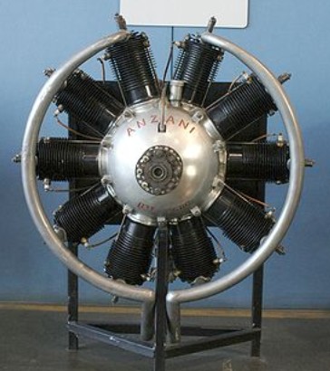
The Anzani 10 was a 1913 10-cylinder air-cooled radial aircraft engine. It powered several experimental aircraft and also the later production versions of the Caudron G.3 reconnaissance aircraft, the Caudron G.4 bomber/trainer and the first production Cessna, the Model AA.
By 1912 Anzani had built the Anzani 10, a 10-cylinder engine, air-cooled like its predecessors, which, like other Anzani engines, was made with different size cylinders. One of the more powerful versions produced about 110 hp (82 kW) from 12.1 litres, a British-built Anzani 10 was rated at 125 hp and a smaller version with a displacement of 8.27 litres produced 80 hp (60 kW). It was a double row engine, built with two rows of five cylinders separated along the crankshaft by about a cylinder radius, giving the engine a slimmer profile than other contemporary two-row radial engines. Each half had its own crankpin, 180° apart, with the connecting rods,of chrome nickel steel, broad and flat to bring the two halves close together. Cylinder heads and pistons were made of cast iron, the latter machined inside and out and fitted with a pair of rings. Oil was forced through the crankshaft to the crankpins, then moved under centrifugal force to the cylinders and pistons from inside the crankcase which was a single light alloy casting.
Both inlet and exhaust valves were in the cylinder heads. The automatic inlet valves of earlier Anzani engines, opened by atmospheric pressure and closed by valve springs were retained, but fuel was fed from a mixing chamber in the crankcase via inlet tubes placed at the rear of the engine to avoid cooling of the mixture by the oncoming airflow. This arrangement placed the exhaust valves at the front of the engine, where they were operated from a cam in the rear of the crankcase via push rods and rockers. A single carburettor fed the crankcase chambers from below. Some versions used a single Gibaud magneto, running at 3,000 rpm, though others built by British Anzani had a pair of Bosch magnetos, running slower. Plugs (K.L.G. for the British variant) were mounted in the sides of the cylinder heads, sloping upwards to avoid plug fouling by lubricating oil. The exhaust was collected by a prominent pair of semi-circular rings.
One British-built 125 hp Anzani 10 underwent exhaustive tests at Farnborough in 1914. Several early aircraft built singly or in small numbers flew with the Anzani 10, but the major users were the Caudron G.3 and G.4, particularly the later ones in which the Anzani replaced the lower powered rotary Gnomes. Numbers of these are uncertain because of the engine change. Because they powered the 66 Caudron G.4s purchased by the American Expeditionary Force after September 1917, used largely as trainers, many Anzani 10s went to the USA. The first production aircraft built by Clyde Cessna, the Model AA was powered by the Anzani 10, and 14 of these were made. Huff-Daland also used them in several aircraft.
Applications
Avro 504 K G-EBWO Blackburn Land/Sea monoplane 1915 Blackburn White Falcon 1915 Blackburn Sidecar 1921 Caudron Type K 1913 Caudron G.3 1914 Caudron G.4 1915 Central Centaur IV 1919 Cessna Model AA 1920s Handley Page Type G 1913 Huff-Daland HD-1B Huff-Daland HD-4 Huff-Daland HD-9A Huff-Daland TA-2 L. and P. biplane Sopwith Grasshopper Sopwith Greek Pusher Timm Collegiate Vickers F.B. 12C 1917
Specifications (110 hp) Type: two-row ten-cylinder radial piston engine Bore: 105 mm (4.13 in) Stroke: 140 mm (5.51 in) Displacement: 12.12 litres (739.8 cu in) Dry weight: 140 kg (308 lb) Valvetrain: One inlet and one exhaust valves/cylinder. Automatic inlet valves, push and rocker operated exhaust valves. Fuel system: Single carburettor mounted between lowest cylinders, mixing chamber in crankcase. Single magneto. Plugs were fitted in the upper side of the cylinder head to avoid fouling. Cooling system: air-cooled Power output: 82 kW (110 hp) Power-to-weight ratio: 0.59 kW/kg (0.36 hp/lb)