Alenia C-27J Spartan

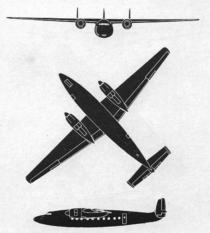
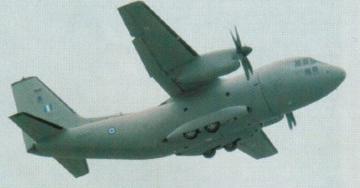
The C 27 J is a joint-venture of Alenia and Lockheed Martin based on the FIAT G222 transport, but with engines and avionics redesigned and made common with the Lockheed C-130J Hercules.
The maiden flight of the prototype (I-CERX) took place from Turin, Italy, on September 25, 1999, and lasted 1 hr 32 min. Crewed by Alenia test pilots the prototype reached 15,000 ft.
The first and second C-27 were converted G.222 aircraft, the third was the first new build.

Alenia C-27J Spartan Article

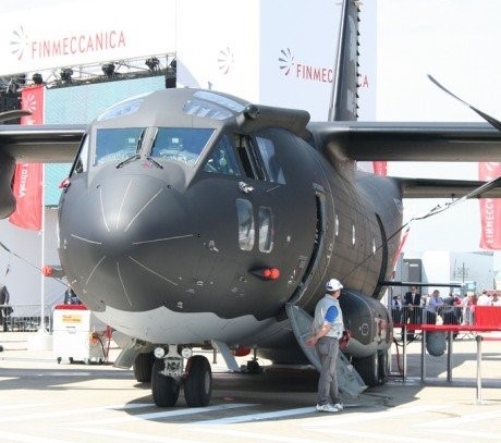
MC-27J is a multimission transport aircraft jointly produced and marketed by Alenia Aermacchi and ATK. It is an armed, roll on/roll off (RO/RO) aircraft based on the C-27J Spartan. Alenia unveiled a new version of the C-27J Spartan battlefield air-lifter, the MC-27J, at the Farnborough International Air Show in July 2012.

The C-27J base platform is slightly modified, while the airlift capabilities of C-27J are retained. The new aircraft is incorporated with pallet-based systems for additional mission-specific capabilities.

The MC-27J can be configured to conduct troop / cargo transport, paratroops / material air-drop, medical evacuation (MEDVAC) and VIP / passenger transport. The gun barrel on the aircraft can be removed to allow reconfigurations for other missions. The aircraft also integrates a fire protection system and an ice protection system.

The two-pilot glass cockpit of the MC-27J is equipped with off-the-shelf avionics and is fully compatible with night vision imaging systems. The avionics suite integrates colour multipurpose displays, multifunction control and display units, optional head-up display units, digital auto-pilot, GPS/INS, identification friend or foe (IFF) transponder, recording systems, terrain awareness warning system (TAWS) and traffic alert and collision avoidance system (TCAS).

The onboard PaWS (palletized weapon system) provides combat capabilities for the MC-27J aircraft. The PaWS is specifically designed for the ATK GAU-23 30mm cannon and other precision guided light munitions. The system minimises collateral damages. The palletised system can be loaded / unloaded through the rear ramp of aircraft. It can be installed in the aircraft within four hours.

MC-27J gunship

The GAU-23 Bushmaster 30mm cannon mounted on the PaWS RO/RO pallet is a chain gun that incorporates features of the M242 and Mk44 25mm cannons. The gun can fire 30mm x 173mm, PGU-13, PGU-15, and PGU-46 ammunition at a rate of 200 rounds a minute. The ammunition is fed into the gun through a dual feed system.

The palletised system also accommodates a reconfigurable mission suite incorporating sensors, communications and mission management system. The aircraft is equipped with electro-optical / infrared targeting sensors, and command, control and communications equipment.

The MC-27J serves as an independent command and control centre interfaced with the ground command network. The aircraft is also equipped to provide signal intelligence (SIGINT) intelligence surveillance and reconnaissance (ISR) capabilities. The target identification systems and weapons systems aboard the aircraft support ground missions.

The MC-27J is powered by two Rolls-Royce AE2100D2A turboprop engines. Each engine, generating 4,637shp power, drives two Dowty six-blade, all-composite propellers. Two full authority digital electronic control units control the engines and propellers.

The onboard electricity is supplied by three generators. The auxiliary power unit (APU) allows the engines to be restarted in flight during emergency conditions.

The fuel system includes four wing tanks and two dedicated fuel feed systems. The aircraft can be optionally fitted with an air-to-air refuelling probe for performing aerial refuelling.

Gallery

Prototype
Engine : 2 x Allison AE 2100 D2, 4142 shp
Props: Dowty 6 blade

Alenia C 27 J Spartan
Engine : 2 x Allison AE 2100 D3, 4142 shp
Length : 74.475 ft / 22.7 m
Height : 32.152 ft / 9.8 m
Wingspan : 94.16 ft / 28.7 m
Wing area : 882.648 sq.ft / 82.0 sq.m
Max take off weight : 66150.0 lb / 30000.0 kg
Weight empty : 36382.5 lb / 16500.0 kg
Max. speed : 305 kt / 565 km/h
Cruising speed : 270 kt / 500 km/h
Initial climb rate : 1968.5 ft/min / 10.0 m/s
Service ceiling : 26247 ft / 8000 m
Cruising altitude : 19685 ft / 6000 m
Wing load : 75.03 lb/sq.ft / 366.0 kg/sq.m
Maximum range : 2484 nm / 4600 km
Range : 1350 nm / 2500 km
Range (max. weight) : 540 nm / 1000 km
Crew : 2
Payload : 53 pax (max 10.000kg)

MC-27J
Engines: 2 x Rolls-Royce AE2100D2A turboprop, 4,637shp
Propellers: Dowty six-blade, all-composite
Length: 22.7m
Wing span: 28.7m
Height: 9.6m
Maximum take-off weight: 30,500kg
Maximum altitude: 30,000ft
Cruising speed: 583km/h
Maximum speed: 602km/h
Maximum range: 1,852km
Ferry range: 5,926km

Alekseyev OKB-21 I-21 / I-211 / I-215

I-215

After working as Lavochkin’s right hand man during World War II, Semyon Mikhailovich Alekseyev was appointed as Chief Designer of OKB-21 at Gor’kiy. The Council of the People’s Commissars directed Alekseyev (among others) to develop jet fighters using more powerful engines than the captured German examples and their Soviet-built copies. The result of Alekseyev’s efforts was the I-21 (istrebitel, fighter) which was planned to be produced in several variants.

The I-21 was a twin-engined all metal single seat jet fighter, with straight wings, mid-set on a round streamlined fuselage, and engines mounted in front of the wings at about one third span. The slightly swept tail unit was cruciform in layout with the tailplane set at approximately half-fin span with slight dihedral. The aircraft’s structure was constructed from high strength B-95 aluminium alloy, high strength steel for highly loaded parts and “Elektron” magnesium alloy for cast fittings. A hydraulically retractable tricycle undercarriage was fitted, using twin wheels for nose and main undercarriages. Hydraullically actuated airbrakes were fitted either side of the rear fuselage.

Construction of the first two airframes began at the end of 1946, with pressure from the Ministry of Aircraft Production to complete initial flight testing by 1 August 1947, to enable the aircraft to take part in the Aviation Day Flypast at Tushino on 18 August 1947. While one of the two airframes initially produced was used for static testing, the other was completed as the I-211 (I-21 version 1) with Lyul’ka TR-1 turbojet engines. (The Lyul’ka TR-2 was the intended powerplant, but was not available). Despite pressure, the I-211 was unable to participate in the Tushino display.

Flight testing started in the Autumn of 1947, but only six test flights had been carried out before the I-211 struck a pothole on landing, which collapsed the undercarriage. Repairs were carried out and the opprtunity taken to replace the TR-1 engines with Rolls-Royce Derwent V engines. The result was the I-215 which had been in development before the first flight of the I-211. Other minor modifications were carried out, the most noticeable being the larger engine nacelles. Despite good results from flight testing the I-215 lost out in production orders to the newer generation of swept winged fighters.

A third I-21 was built as the I-215D (dooblyor, second prototype), with a bicycle undercarriage, using wider-diameter paired wheels in a bicycle arrangement, retracting into the fuselage, along with small outrigger wheels under the engine nacelles which retracted into fairings, to order from OKB-1. This was used to test this arrangement for “Aircraft 150” and other projects (OKB-1 was supervised by Dr. Brunolf Baade, who later designed the VEB type 152 airliner, in the DDR, as a direct descendent of “Aircraft 150”, and indirectly of the I-215D). The main undercarriage of the I-215D also incorporated a kneeling feature which could increase the incidence of the aircraft by 3 degrees to assist take-off. Trials with this undercarriage arrangement proved successful and paved the way for its use in many other Soviet aircraft.

Armament of the I-211 comprised two, three, four, or six cannon in the chin, depending on variant.

Variants:
I-210 – The initial version with Tumanskii RD-20 (BMW 003 copy) engines. Not proceeded with due to availability of Lyul’ka TR-1 engines.

I-211 – The first flyable example completed as the I-211 with Lyul’ka TR-1 engines, rebuilt as the I-215.

I-211S – I-211 with swept wing and tail.

I-215 – The re-built I-211 with Rolls-Royce Derwent V engines and other minor modifications.

I-215D – Bi-cycle undercarriage I-215 built to order of OKB-1.

I-216 – Proposed “Heavy” fighter version of the I-215 with two 75mm cannon and modified outer wings.

I-215

Specifications:

I-211
Engines: 2 × Lyul’ka TR-1 jet, 1,300kgp (2,866 lb st)
Wingspan: 12.25 m (40 ft 2.28 in)
Wing area: 25 sq.m (268.8 sq.ft)
Length: 11.54 m (37 ft 11.9 in)
Loaded weight: 6.890 kg (15,189 lb)
Maximum speed: 970 K/h (524.32 mph)
Ferry range: 1,550 km(962 miles)
Service ceiling: 13,600 m (44,619 ft)
Rate of climb: 27.78 m/s (5416 ft/min)
Armament: 2 x 23mm cannon
Crew: 1

Albatros Werke L.73

An eight-passenger biplane airliner of 1926, powered originally by two 179kW BMW Va engines, but subsequently fitted with 268kW BMW Vas. Four were built for Luft-Hansa, flying night sections of several domestic and international routes until the early 1930s. Two were later sold to Bulgaria
A luxurious aircraft for its time, the L73 featured reclining seats for all passengers.

Engine: 2 x BMW IV, 280kW
Wingspan: 19.7 m / 64 ft 8 in
Length: 14.6 m / 47 ft 11 in
Height: 4.7 m / 15 ft 5 in
Wing area: 92.0 sq.m / 990.28 sq ft
Take-off weight: 4600 kg / 10141 lb
Empty weight: 1690 kg / 3726 lb
Max. speed: 158 km/h / 98 mph
Cruise speed: 145 km/h / 90 mph
Ceiling: 3000 m / 9850 ft
Range w/max.fuel: 600 km / 373 miles
Crew: 2
Passengers: 8

Albatros Werke G.II / G.III

The G.II prototype first flew in mid-1916 and G.III entered service in Macedonia and elsewhere in the following year. Armament comprised two Parabellum machine-guns – one each in nose and rear cockpits – plus 320kg of bombs.
A medium bomber powered on the G.III limited production version by two 164kW Benz Bz.IVa pusher engines mounted on the lower wings. The trailing-edges of the inner sections of the lower wings were cut away to allow the engines and propellers to be fitted further forward on the wings than would otherwise be possible.

Engine: 2 x Benz Bz IVa, 147kW
Wingspan: 18.0 m / 59 ft 1 in
Length: 11.9 m / 39 ft 1 in
Height: 4.2 m / 13 ft 9 in
Wing area: 79.0 sq.m / 850.35 sq ft
Take-off weight: 3150 kg / 6945 lb
Empty weight: 2064 kg / 4550 lb
Max. speed: 150 km/h / 93 mph
Range w/max.fuel: 600 km / 373 miles
Crew: 3

Akaflieg Berlin B-9

To practically test the position of the pilot, the Flugtechnische Fachgruppe (Aero-technical Group) Stuttgart constructed the FS17 research aircraft. The FS17 was a glider that was designed to withstand forces up to 14g. After the completion of the test program an order was given by the DVL ((Deutsche Versuchanstalt für Luftfahrt e.V. Berlin-Aldershof) (German Experimental Department for Aerospace Reg.) to the FFG Berlin ((Flugtechnische Fachgruppe)(Aero-technical Group)) to construct a powered aircraft. FFG Berlin was chosen as it possessed the necessary workshops and technicians. In the Spring of 1943 the FFG Berlin constructed the Berlin B9 to the specifications provided.

The Berlin B9 is a low winged type aircraft of standard layout. It is of mixed construction and stressed to accept 22g. The fuselage is constructed of steel tubing covered by timber ribbing and fabric covering. The fuselage is trapezoidal in cross-section. Its largest frame has an area of 0.67sq.m. The fuselage diminishes in area towards the rear and finishes in the empennage. The cockpit is covered with a 1.5m long, clear canopy that is jettisonable. The fuselage bolts to the wings at four points.

The single leg retractable undercarriage is borrowed from the Me108. It is raised and lowered by a hand ratchet.
The empennage consists of a fin with balanced rudder and elevators that is attached to the end of the fuselage. The elevators have a range of 30 per cent (27 degrees).

The wing assembly consists of a rectangular centre section and two trapezoid like outer sections. The leading edge is square to the fuselage for half of its length. At the point where the outer panel is connected, a trail of 2 degrees is introduced. This is held for the remaining length of the wing.

The wing is constructed of two box like spars. These are situated at 20 per cent and 50 per cent through the wing from the leading edge. Dural sheets are glued to the spars for the purpose of providing attachment points for the wing to the fuselage and the engine to the wing. Solid planking to withstand the torsional forces generated by high acceleration manoeuvrers covers the area between the spars. The mounting struts for the motors are situated within the engine nacelles. The four fuel tanks are placed between the spars on either side of the motors.
The rudder and flaps mechanisms are situated just behind the last wing spar. The flaps are situated below the fuselage. They are 20 per cent of the width of the wing and can be extended to 60 degrees.

Two Hirth Type HM500 motors generating 105 PS drive two fixed pitch Schäfer propellers.

The aircraft was designed to accommodate a pilot lying in the prone position. As such it needed a flight control system that did not load up under high acceleration and needed no extra pilot training to be able to use. A fundamental change to the flight controls was out of the question. The decision was made to employ a control column instead of a control wheel.

Cockpit layout is far more important in an aircraft designed for prone operation that in an aircraft where the conventional sitting position is employed. The cockpit must be layed out in a definite right and left side pattern. Crossing hands to manipulate controls in the prone position creates significant difficulties for pilots. Blohm & Voss encountered this problem with control columns in some of their work. They also discovered that by using a small control column, the left hand could also be used to control the aircraft if the right hand was incapacitated.
In the Berlin B 9, the right hand is used to control the elevators and ailerons. It is also given the task of releasing the pilots harness and the canopy release. The left hand operates all the other controls and instruments. The feet, in the same fashion as in a conventional sitting position, operate the rudder and brakes.

In the FS17 and the first mockups of the Berlin B 9, the control column was situated centrally. In the finished Berlin B 9, the control column was located asymmetrically and approved for right-handed flight only. Even so, the left hand can be used to control the aircraft if necessary. This design change severely restricts the downward field of view to the point where ground observation is not one of the strong points of this aircraft.

The Berlin B 9 was completed in the Spring of 1943, and under the supervision of H.W. Lerche of the experimental station at Rechlin, the aeroplane made it’s first test flight.

As of August 1943, the Berlin B 9 was presented to official Departments involved. By November 1943 thirty pilots had flown and evaluated the aeroplane. Only one accident occurred during the entire program. This occurred when a pilot made an error that may have ended up in an aborted take-off. The damage was repaired within three weeks.

The prone position of the pilot was generally indicated as being comfortable. On occasion there was a request for softer upholstery. Fatigue and tiredness was experienced in the neck (from head lifting) and shoulder muscles from moving the upper arms and the incorrect positioning of the parachute harness. Flying in a combination of winter equipment and heavy furs was noted as being tiring.

Pilots who flew the aircraft often soon adjusted to the prone position and were able to make 1 ½ hour flights without discomfort.

A chin support was considered bothersome in horizontal flight. The cockpit configuration without the chin support and the parachute on the pilot’s back was favoured most pilots. Although under high g loads a chin support was seen as being imperative. The control column was changed to become vertical and was accepted as being more comfortable by the pilots. The forces need to control the aircraft were considered as being too low. Most pilots were used to controlling much heavier aircraft. As a result, the gearing of the rudder control was changed to increase the load needed to move the rudder in flight. Several pilots took some time to get used to the feel of the rudder. No problem was encountered with the amount of force needed to operate the elevators. Cramps that developed in flight caused some difficulty to the pilots. By performing rolling exercises on the ground, leg muscles soon became accustomed to the position and cramps ceased to develop. Pilot’s legs were very sensitive to the wrong length settings for the pedals.

The Berlin B 9 was able to achieve accelerations of 8.5g when pulling out of dives and 6g over several seconds in steep spiral climbs. Accelerations of these magnitudes are not endurable by pilots when in the normal seated position. At the beginning of the test program, these forces were only recognised by the heaviness of the head and limbs. These forces did not impair the pilot’s mental and physical reactions. Because of this, pilots often underestimated the number of gs they had pulled.

The Berlin B 9’s speed and ability to generate higher forces was restricted by the fixed pitch and relatively low rotational speed, Schwarz propellers.

The Berlin B 9, had shown how prone cockpits not only resisted g better but also reduced frontal area.

Pilots who flew in the Berlin B 9:

  1. Eingeflogen durch Haupt-Ing. H.W. Lerche, Rechlin – 10. 4. 43
  2. Ing. L. Schmidt, FFG Berlin (Flugerprobung) – 14. 4. 43
  3. Dipl.-lng. E. G. Friedrichs, FFG Berlin und DVL (Flugerprobung) – 14. 4. 43
  4. Dr. med. H. Wiesehöfer, DVL – 15. 6. 43
  5. Ing. H. Schuhmacher, DVL – 6. 7. 43
  6. Dr. Ing. Doetsch, DVL – 17. 7. 43
  7. Prof. Kurt Tank, Focke-WuIf – 30. 7. 43
  8. Flugzeugführer Bartsch, Focke-WuIf – 31. 7. 43
  9. Flugbaumeister Mehlhorn, Focke-WuIf – 31. 7. 43
  10. Lt. Scheidhauer, Sonderkommando Horten – 29. 8. 43
  11. Flugzeugbaumeister Malz, RLM-GL/C-E2 – 9. 9. 43
  12. Stab-Ing. Czolbe, RLM-GL/C-E2 – 9. 9. 43
    13 Flugkapitän Rodig, Blohm & Voss – 15. 9. 43
  13. Flugzeugführer Rautenhaus, Blohm & Voss – 15. 9. 43
  14. Flugzeugführer Hilleke, Blohm & Voss – 15. 9. 43
  15. Stabs-Ing. Bader, Rechlin E2 – 23. 9. 43
  16. Dipl.-Ing. Th. Goedicke, Rechlin E2 – 23. 9. 43
  17. Stabs-Ing. Neidthard, Rechlin E2 – 23. 9. 43
  18. Stabs-Ing. H. Böttcher, Rechlin E2 – 23. 9. 43
  19. Stabs-Ing. Thoenes, Rechlin E2 – 23. 9. 43
  20. Hauptmann Behrens, Rechlin E2 – 23. 9. 43
  21. Flugkapitän Bauer, Messerschmitt – 1. 10. 43
  22. Flugkapitän Heini Dittmar, Messerschmitt – 2. 10. 43
  23. Flugkapitän Wendel, Messerschmitt – 2. 10. 43
  24. Dipl.-Ing. Kracht, DFS-Ainring – 5. 10. 43
  25. cand. Ing. Model, DFS-Ainring – 6. 10. 43
  26. Dipl.-Ing. Zacher, DFS-Ainring – 6. 10. 43
  27. Flugkapitän Zitter, DFS-Ainring – 12. 10.43
  28. Dipl.-lng. G. Ziegler, DFS-Hörsching – 13. 10.43
  29. DipI.-lng. F. W. Winter, DFS-Hörsching – 13. 10.43
    31 Stabs-Ing. Beauvais, Rechlin E2 – 27.10. 43
  30. Haupt-Ing. Strobl, Rechlin E2 – 28. 10.43
  31. Oblt. Brüning, Rechlin E2 – 28. 10.43

Engines: 2 x Hirth Type HM500, 105 PS
Props: Fixed pitch
Drive: Direct
Diameter: 2.00m
Number of blades: 2
Rotation: Right
Swept area: 2×3.14sq.m
Wingspan: 9.40m
Length max: 6.06m
Height max: 2.32m
Wheel track: 2.84m
Tyre size: 550x150mm
Tyre pressures: Medium
Wheel brakes Hydraulic
Fuel capacity: 95 lt
Oil tank capacity: 8 lt
Wings and fin: 11.9 sq.m
Rudder: 0.488 sq.m
Flaps (total): 0.666 sq.m
Wing chord 7.45
Wing planform: Right-angle trapezoid
Dihedral: 4 degrees
Stress loading: +22g
Depth at wing root: 1.48m
Depth, fuselage: 0.845m
Average fuselage depth: 1.266m
Stabiliser area: 1.365sq.m
Elevator area: 0.585sq.m
Total area: 1.95sq.m
Span: 3.00m
Fin area: 1.07sq.m
Rudder area: 0.63sq.m
Total area: 1.70sq.m
Height: 1.52m
Net weight: 940kg
Payload: 175kg
Take-off weight: 1115kg
Endurance: 1 hr 50 mins
Flight radius: 400km
Fuel consumption: 22 lt/100km
Max speed: 250km/h
Cruising speed: 225km/h
Landing speed: 105km/h
Operational ceiling: 4000m
Time to 1000m: 4 min 12 sec
Wing loading: 94kg/sq.m
Power to weight ratio: 5.3kg/PS
Surface area loading: 17.7PS/sq.m
Propeller performance: 33.4PS/sq.m

AirUtility Cargo Co AU18-150 / AU-27

The AU18-150 lightweight twin-engined monoplane was developed by the AirUtility Cargo Company as a single-seat carrier aircraft, for a variety of detachable pods which can be mounted under the centre section.

Designed by Elsworth Gardenhire, the AU18-150 lightweight twin-engined monoplane was developed by the AirUtility Cargo Company as a single-seat carrier aircraft, for a variety of detachable pods which can be mounted under the centre section. The twin-boom, twin-tail fuselages had a pilot’s pod atop the wing midsection.

First flying on 18 April 1949, N68819 retired after its final flight in 1958.

AirUtility AU-18 N68819

Modifications led to 1954 designation as AU-18-150B, as well as experimental AU-27 with 130hp Lycoming O-290, a ground-support plane for military trials.

AU18-150
Engines: 2 x Continental A75-8, 75 hp
Wingspan: 39 ft 10.5 in
Length: 21 ft 11 in
Empty weight: 1322 lb
Loaded eight: 2119 lb
Useful load: 797 lb
Max speed: 125 mph
ROC: 850 fpm
Seats:1

AU-18-150B

AU-27
Engines: 130hp Lycoming O-290
Wingspan: 48’6″
Length: 28’3″

Airtech CN-235

Developed by CASA of Spain and IPTN of Indonesia, and marketed by the joint company of Aircraft Technology Industries (AirTech), the CASA/IPTN-designed, General Electric CT7-powered CN-235 first flew in I November 1983. In military configuration a 15,000kg payload may be carried, comprising 48 passengers, 41 paratroops, or 24 stretchers.

Airtech CN-235 Article

Orders to 1990 were nearing 200, with a majority for military operators, including the air arms of Spain Indonesia and those of France, Saudi Arabia, Ecuador, Botswana, Panama, Morocco and Turkey – where the CN-235 will also be assembled.
Export deliveries began in February 1987, when the Royal Saudi Air Force received the first of four aircraft. Jordan
ordered two in 1985, while the Indonesian armed forces will receive 50, comprising 32 for the Air Force and 18 for the Navy. At least six of the latter will be of the maritime surveillance version, with equipment including a 360 degree-scan search radar, AM.39 Exocet anti-shipping missiles, and Mk.46 torpedoes.

CN.235-100
Engine: 2 x GE CT7-9C turboprops, 1,870 shp (1 394 kW)
Installed pwr: 2536 kW
Span: 25.8 m
Length: 21.3 m
Wing area: 73 sq.m
Empty wt: 8600 kg
MTOW: 14,400 kg
Payload: 5000 kg
Cruise speed: 454 kph
Initial ROC: 540 m / min
Ceiling: 8110 m
T/O run: 554 m
Ldg run: 585 m
Fuel internal: 5268 lt
Range/payload: 600 km with 5000 kg
Capacity: 38/40 pax

Airspeed AS.57 Ambassador

In 1943, the British government formed a committee under the chairmanship of Lord Brabazon of Tara to identify post-war civil aviation requirements. In its February 1943 report, they recommended a twin-engined, unpressurised design in the 14.5 tonnes gross weight class, short to medium-range piston-engined aircraft for British operators and for sale to European airlines.
The Airspeed AS.57 Ambassador was designed by a team headed by Arthur Hagg, their work taking shape on the drawing-board while the UK was still at war. Spanning 115ft and 81ft long, the Ambassador had two Bristol Centaurus 661s, each developing 2,700 hp and driving a 16ft 6in diameter four bladed de Havilland propeller.
A normal capacity of 47 passengers was envisaged with an all up weight would be 52,500 lb, with ranges of 720 and 1,560 miles at cruising speeds of 280 and 220 mph respectively.

There was capacity for future “stretch”, and the wings were designed with strongpoints to accommodate a future powerplant change to four propeller turbines of the Rolls Royce Dart type.

By the time the British Ministry of Aircraft production ordered two prototypes from Airspeed Ltd., immediately after the end of the World War II, the design had grown. The Ambassador would be pressurised and have a maximum gross weight of almost 24 tonnes, offering seating for 47 passengers. The Ambassador was a high-wing monoplane with triple fins, retractable nosewheel.

The Ambassador was of cantilever high-wing monoplane configuration of all-metal construction, with its fuselage stressed for cabin pressurisation. The three-finned tail unit was car¬ried high on an upswept aft fuselage, and the retractable tricycle landing gear incorporated twin wheels on each unit.

The prototype (G-AGUA) powered by two 2.600 hp Centaurus 631 radials, was first flown on 10 July 1947 from Christchurch. In 1948 the first (and also the only) order for 20 Ambassador 2s was received from British European Airways. The second prototype (G-AKRD) flew on 26 August 1948; two static-test airframes were built, followed by one pre-production Ambassador (G-ALFR) which was used to obtain the C of A and for route proving by BEA – British European Airways. Airspeed AS57 Ambassador G-ALFR had the definitive Centaurus 661 powerplant, and was flown first in May 1950.

British European Airways (BEA) ordered 20 pressurised Ambassadors on 20 September 1948. Problems with the engines, undercarriage and pressurisation system delayed service introduction until 13 March 1952.
The Ambassadors were called ‘Elizabethan’ class by BEA.

On 13 March 1952, the first British European Airways service London-Paris was inaugurated, with 47 seats and 2,012kW Centaurus 661. BEA called its fleet “Elizabethans” in honour of the newly crowned Queen Elizabeth 1, during their six years of operation. In 1954, after two years’ service, BEA requested clearance of an increased maximum take off weight from 52,500 lb to 55,000 lb. This was achieved.
After service with BEA the Ambassador passed to several independent airlines including BKS, Dan-Air and Globe Air of Switzerland – some serving as freighters and horse transports. Three were used for a time by Butler Air Transport in Australia, and one was owned by the King of Morocco.
The second AS.57 prototype (G-AKRD) was later used for development testing of the Bristol Proteus 705, Rolls¬Royce Tyne and Rolls-Royce Dart turboprops, and was still airworthy in 1969.
The third prototype (G-ALFR), was used for testing of the Napier Eland turboprop, but was later converted to airline standards and sold to Dan Air.
Only 23 Airspeed Ambassadors were produced.

Gallery

Engine: 2 x Bristol Centaurus 661 two-row sleeve-valve radial piston, 1939-kW (2,600-hp)
Wing span: 35.05m (115 ft 0 in)
Length: 24.69m (81 ft 0in)
Height: 5.59m (l8ft 4in)
Wing area: 111.48sq.m (1,200 sq.ft.)
Max take-off 23814 kg (52,500 lb) – 55000.0 lb / 24947.0 kg
Empty equipped weight: 16230 kg (35,781 lb)
Max. speed : 271 kts / 502 km/h
Maximum cruising speed: 438 km/h (272 mph)
Economic cruising speed: 399 km/h (248 mph)
Range with maximum payload: 1159 km (720 miles).
Range w/max.fuel: 1930 km / 1199 miles
Service ceiling : 36089 ft / 11000 m
Crew: 3
Pax cap: 47