Airspeed AS.10 Oxford / AS.65 Consul

Oxford

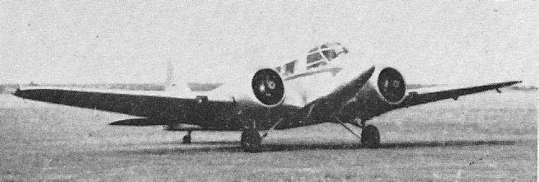
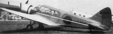
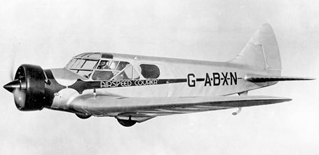
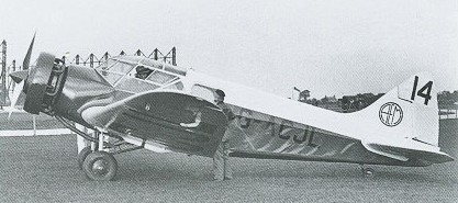
In 1936 Airspeed submited a proposal to meet Air Ministry Specification T.23/36, for a twin-engined trainer. Airspeed’s design for this was based on the AS.6 Envoy, which may have helped the Air Minis-try’s decision to order an initial quantity of 136 AS.l0s.

Airspeed AS.10 Oxford Article

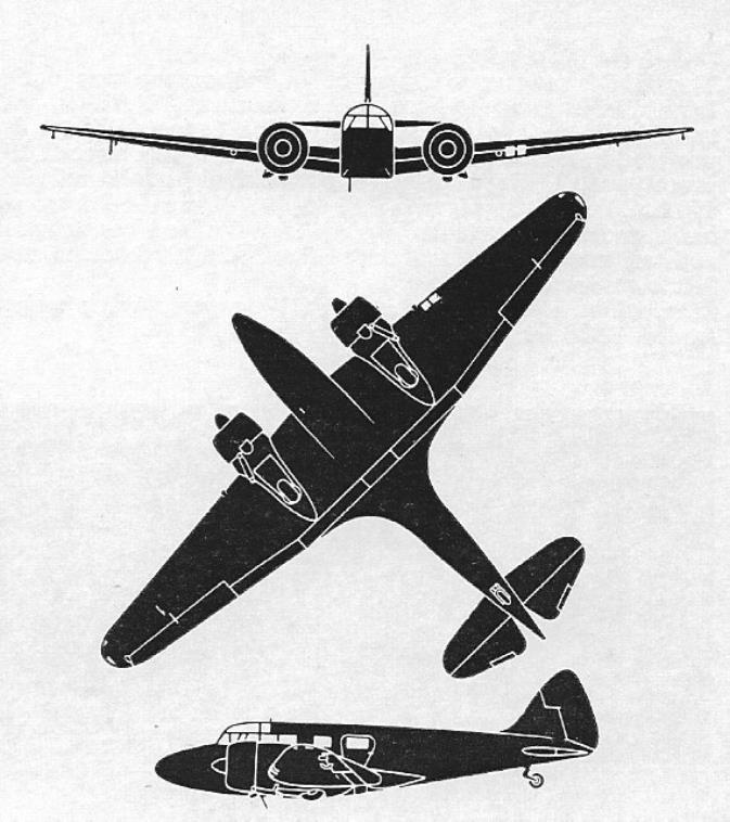
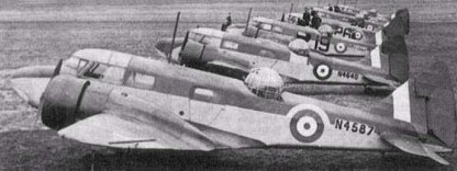
Sharing the AS.6 Envoy wooden construction, tailwheel type retractable landing gear and basic air¬frame, normal accommodation was for a crew of three at any one time, but in addition to seats for a pilot/pupil and co-pilot/instructor, there were positions for the training of an air-gunner, bomb-aimer, camera operator, navigator, and radio operator. Dual controls were standard, making the Oxford suitable for use as a twin-engined trainer; with the dual-control set removed from the co¬pilot’s position, a bomb aimer could take up a prone position and drop practice smoke bombs which were carried in the centre-section well; or the seat could be slid back and a chart table, hinged to the fuselage side, erected for use by a trainee navigator; an aft-facing seat behind the co-pilot position was available for a radio operator; and, in the Oxford 1, an Armstrong Whitworth dorsal gun turret was provided for an air-gunner’s training. The turret was removed from later versions and they were used mainly for pilot training. A hood was also available so that the Oxford could be used for instrument training.

Oxford

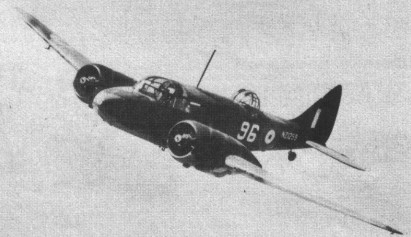
The prototype AS.10 Oxford made its first flight on 19 June 1937, and deliveries began in November of that year, with four of the first six going to the RAFs Central Flying School, the other two to No.11 Flying Training School.

One example of a Mk II aircraft was fitted experimentally with two 186-kW (250-hp) de Havilland Gipsy Oueen inline engines. Odd variants included an early Oxford I equipped with special McLaren landing gear, the main units of which could be offset to cater for a reasonable degree of crosswind at both take-off and landing, and one with a tail unit which included twin endplate fins and rudders, especially installed for a series of spin recovery tests.

The outbreak of World War II created a demand for these trainers, not only for use by the RAF, but also by those nations which were involved in the Commonwealth Air Training Scheme. These included Australia (nearly 400 Oxfords), Canada (200), New Zealand (300), Rhodesia (10), and South Africa (700). Examples went also to the Free French air force and, under reverse Lend-Lease, a number were used by USAAF units in Europe. A number were equipped to serve as air ambulances. The Fleet Air Arm also had one training unit, No. 758 Instrument Flying Squadron, equipped with Oxfords from June 1942.

The demand for Oxfords was beyond Airspeed’s productive capacity, the company building a total of 4,411 at Portsmouth, Hants, and 550 at Christchurch, Hants. Other construction was by de Havilland at Hatfield (1,515), Percival Aircraft at Luton (1,360), and Standard Motors at Coventry (750), to give a total of 8,586. Airspeed built its last example in July 1945, and the Oxford remained in service with the RAF at No. 10 Advanced Flying Training School, Pershore, until 1954. Many were supplied after the war to the Dutch air force.

Consul

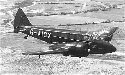
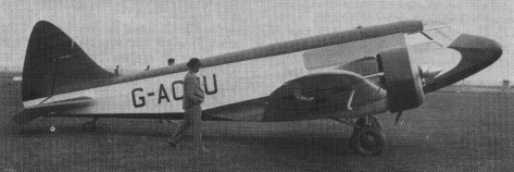
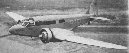
During 1946-1948 many were converted to Consul civil version status post-war as civilian six passenger aircraft. About 150 were sold worldwide, some conversions and some new builds.

Gallery

Mk I – Weapons trainer, usually fitted with a Armstrong Whitworth dorsal gun turret
Engines: 2 x Armstrong Siddeley Cheetah IX (335hp) or Cheetah X, 280-kW (375-hp).
Propellers: Fixed-pitch
Length: 34.48ft (10.51m)
Wingspan: 53.31ft (16.25m)
Height: 11.09ft (3.38m)
Maximum Speed: 186mph (300kmh; 162kts)
Cruise: 140 mph
Maximum Range: 932miles (1,500km)
Service Ceiling: 19,199ft (5,852m)
Armament: 1 x 7.7mm (0.303-in) Vickers K machine gun in dorsal turret
Bombload: 250lbs internal
Accommodation: 3
Empty Weight: 5,379lbs (2,440kg)
Maximum Take-Off Weight: 7,599lbs (3,447kg)

Mk II – Pilot, radio-operator and navigator trainer
Engines: 2 x Armstrong Siddeley Cheetah IX (335hp) or Cheetah X, 280-kW (375-hp)
Propellers: Fixed-pitch
Top speed: 185 mph
Cruise: 140 mph

Mk.II
Engine: 2 x Armstrong Siddeley Cheetah 10, 395 hp
Span: 43 ft 4 in
Length: 35 ft 4 in
Height: 10 ft 1.5 in
Wing area: 348 sq.ft
Empty weight: 6047 lb
Loaded weight: 8250 lb
Top speed: 185 mph
Max cruise: 156 mph
ROC: 1180 fpm
Max range: 900 mi

Mk III – Radio and navigation trainer
Engines: 2 x Armstrong Siddeley Cheetah XV 318-kW (425hp)
Propellers: Rotol constant-speed
Number built: 1

Mk IV – Testbed for the De Havilland Gipsyqueen IV (Gipsy-Six IIIS,
Turbocharged, 6 cylinder inline engine).

Mk V – Radio and navigation trainer
Engines: 2 x Pratt & Whitney R 985-AN6 Wasp Junior, 335kW (450-hp)
Propellers: Constant-speed
Wingspan: 16.26 m / 53 ft 4 in
Length: 10.52 m / 34 ft 6 in
Height: 3.38 m / 11 ft 1 in
Wing area: 32.33 sq.m / 348.00 sq ft
Max take-off weight: 3269 kg / 7207 lb
Empty weight: 2572 kg / 5670 lb
Wing load: 22.96 lb/sq.ft / 112.0 kg/sq.m
Max. speed at 1250m (4,l00ft): 325 km/h / 175 kts / 202 mph
Service ceiling: 6400 m / 21000 ft
Range: 1127 km / 609 nm / 700 miles
Seats: 3-4

Oxford
Consul

Airspeed AS.8 Viceroy

In parallel with the design work on the Envoy, Tiltman was also working on the Cheetah engined machine for Stack. This required so many variations from the basic Envoy that it was designated the A.S.8 Viceroy.
A batch of six machines was laid down, the initial flight test of the prototype, G ACMT, being scheduled for April 1934. Maximum effort was made on the prototype, but modifications to the airframe and the complexity of building with different engines caused much delay. At Farnborough deep prejudice existed over cantilever wings, and they demanded a 25 per cent increase in the load factor. After four months negotiation, and Tiltman testing a complete wing to destruction proved this increase was unnecessary.
On June 26, 1934, FIt Lt C. H. S. Colman, Airspeed’s test pilot, flew ‘CMT for the first time. It handled extremely well with no snags, and was demonstrated at the Society of British Aircraft Constructors’ Show at Hendon on July 2.
The certification trials at Martlesham Heath were troubled, mainly with the Wolseley engines, in which two fuel pump spindles sheared. A failed gasket in the hydraulic system caused the machine to land with one undercarriage leg half down, with consequent damage and delay, and the fuel tanks developed leaks. The major problem, was that the machine was overweight, and its single engine performance was not satisfactory. It was felt that the new Wolseley IB engines would cure this defect. Generally, the test pilots were extremely impressed with the handling and performance of the Envoy, and a Certificate of Airworthiness was, issued on October 9, 1934.
All entries in the Australia Race had to be handed over to the Royal Aero Club scrutineers by October 14. The manufacturers of the Viceroy’s engines and automatic pilot failed to keep their delivery promises, and the machine did not fly until September 19. To add to Airspeed’s problems, the engine revs were low and the weight high. Its 315 hp Cheetah VI engines gave it a top speed of 210 m.p.h. (338 km/hr) at 7,000ft (2,135m). It cruised at 190 mph (306 km/hr) and, with a massive long range fuel tank in the cabin, had a range of 1,400 miles (2,253km).
To save time, a Martlesham test pilot flew to Portsmouth to carry out the C of A trials. The machine was completely satisfactory and displayed a top speed of 210 mph (338 km/hr).
The MacRobertson Race to Australia was in two sections, absolute speed and handicap with a maximum elapsed time. The Viceroy was so heavily handicapped as to have virtually no chance of success. Stack’s Viceroy was forced down at Abbeville in Northern France with electrical trouble. The weather was foul. He soon took off again for Marseilles, but returned almost immediately. During the evening of October 20 he left for Rome, reached Athens and withdrew from the race. At the end of 1935 Stack and Turner sued Airspeed for “the recission of a hire purchase agreement and repayment of £2,448 paid by them for the Viceroy.” They alleged that Airspeed had been negligent in failing to ensure that the aircraft was fully airworthy. The case was settled out of court, the plaintiffs withdrawing all their allegations and agreeing to return the Viceroy to the Company with a further payment of £1,850.

Airspeed AS.6 Envoy

AS.6 Envoy

The design of the AS.6 Envoy, began in late 1933 as and Hessell Tiltman, the technical director and chief designer based it on the Courier and using as many common parts as possible and their new Javelin or the Wolseley A.R.9 engine. T. Neville Stack was finally content with a Cheetah-engined machine with a cruise speed of 180 mph and endurance of six hours.

Tiltman followed the same basic construction as the Courier. The airframe was of wooden construction, the fuselage was a semi monocoque structure in two sections, the front fuselage comprising the cockpit, cabin, toilet and luggage compartment and the rear fuselage carrying the tail unit. The doors and windows were built integrally with the sides and the stressed ply skin cut away before assembly. All the major fuselage sections were jig built with longerons of spruce and a skin of birch ply laid at an angle of 450. No diagonal bracing was needed, as the skin carried all the shear loads, bending loads being carried by the longitudinal members.
The fuselage shell comprised two sides, a bottom and a top panel, to form a light, rigid box. The top and bottom curvature was formed with formers and stringers covered in fabric. With accommodation for a pilot and eight passengers the Envoy had all control surfaces fabric-covered, and a retractable tailwheel type landing gear and a variable-incidence tailplane were fitted.

Three versions were produced. The Series 1 and 2 Envoys had a twin spar wing with Warren girder inter spar bracing. The leading edge was covered by 1mm ply, and the wing was fabric covered. It was stiff in torsion and was complicated to build. The Series I (17 examples built) was without trailing-edge flaps; the Series II (13 built) introduced hydraulically operated split flaps which extended from the aileron to wing root on the trailing edge of each wing, and also from wing root to wing root beneath the centre-section. With flaps down the stalling speed was reduced by 11 mph (177 kph). The Series III (19 built) was similar, but had a number of detail improvements. The Series 3 Envoy, introduced at the end of 1936, was built with a ply-covered wing, the two spars forming a torsion box to eliminate the Warren girder bracing and give a stronger and stiffer wing. The production time for the wing was reduced by 35 40 percent. The tail unit was a wooden structure, fabric covered. The undercarriage, operated by a hydraulic handpump, was geometrically and functionally similar to the Couriers.

A.S.6Jc Envoy III

In parallel with the design work on the Envoy, Tiltman was also working on the Cheetah engined machine for Stack. This required so many variations from the basic Envoy that it was decided to identify it as the A.S.8, to be known as Viceroy.

Soon after the 1934 SBAC Show at Hendon, Tiltman received from the Air Ministry an in¬vitation to tender for an Envoy con¬verted to a Coastal Patrol aircraft. Nothing more was heard of the project.

The prototype first flew on 26 June 1934 and 50 were built, including the pro¬totype, by Airspeed for British, Japanese, Czechoslovakian, and Chinese. South Africa acquired seven En¬voys in 1936: three of these were used by the SAAF and had an armament com¬prising a forward firing machine-gun and a dorsal gun turret. The four civil Envoys which made up the total, and which were for operation by South African Air¬ways, were capable of quick conversion for use in a military role. A small number were supplied to the RAF. A number were used in the Spanish Civil War. Mitsubishi also built a number under licence.

Engines fitted to Envoys included the Wolseley AR.9, Scorpio I or Aries III, Armstrong Siddeley Lynx IVC or Cheetah IX, Wright Whirlwind R.760 and Walter Castor II.

AS.6
Engine: 2 x Wolseley AR.9, 149-kW (200-hp)

AS.6A
Engine: 2 x Armstrong Siddeley Lynx IVC, 179-kW (240-hp)

AS.6D
Engine: 2 x Wright R-760-E2 Whirlwind 7, 261 -kW (350-hp)

AS.6E
Engine: 2 x Walter Castor II, 254-kW (340-hp)

AS.6G
Engine: 2 x Wolseley Scorpio I, 186-kW (250-hp)

AS.6H
Engine: 2 x Wolseley Aries III, 168-kW (225-hp)

AS.6J
Engine: 2 x Armstrong Siddeley Cheetah IX, 261-kW (350-hp)
Maximum speed at 2225m (7,300ft): 338 km/h / 183 kts / 210 mph
Cruising speed at 3050m (10,000ft): 290 km/h / 157 kts / 180mph
Service ceiling 6860m (22,500ft)
Range: 1046 km / 565 nm / 650 miles
Empty weight: 1840kg (4,057 lb)
Maximum take-off weight: 2858 kg (6,300 lbs)
Wing span: 15.95m (52ft 4in)
Length: 10.52m (34ft 6in)
Height: 2.9m (9ft 6in)
Wing area: 31.49 sq.m (339sq.ft)
Wing load: 18.66 lb/sq.ft / 91.0 kg/sq.m

A.S.6Jc Envoy III
Engines: 2 x Armstrong Siddeley Cheetah A.S.9, 375 hp
Span: 52 ft 4 in
Length: 34 ft 0 in
Height: 9 ft 6 in
Empty weight: 4340 lb
Loaded weight: 6600 lb
Max speed: 203 mph
Cruise: 170 mph
Range: 620 mi

AS.6JM/C
Engine: 2 x Armstrong Siddeley Cheetah IX, 261-kW (350-hp)
Take-off weight: 2960 kg / 6526 lb
Empty weight: 1920 kg / 4233 lb
Wingspan: 15.9 m / 52 ft 2 in
Length: 10.5 m / 34 ft 5 in
Height: 2.8 m / 9 ft 2 in
Wing area: 31.5 sq.m / 339.06 sq ft
Max. speed: 325 km/h / 202 mph
Cruise speed: 270 km/h / 168 mph
Ceiling: 6700 m / 22000 ft
Range: 990 km / 615 miles
Crew: 2
Passengers: 6

Airspeed AS.5 Courier

A light transport of conventional all-wood construction, with all control surfaces fabric-covered, of 1935. The first British aircraft with retractable undercarriage to go into production, a five-six-seat cantilever low-wing cabin monoplane.

First flown on 11 April 1933 (G-ABXN) from Portsmouth, four days later it crashed at Portsmouth, receiving minor damage. Repaired, it had another accident at RAF Martlesham Heath. It was used in aerial refuelling experiments by Sir Alan Cobham, using two Handley Page W10s as aerial tankers. The experiments led to an attempt of a non-stop flight to India that started at Portsmouth on 24 September 1934. It ended the same day when Cobham had to make a forced landing at Malta, due to a broken throttle; in the event the Courier was damaged. The aircraft was impressed into the RAF in June 1940, s/n X9427.

Sixteen were built with a total of 15 production aircraft.

Gallery

AS.5A
Engine: Armstrong Lynx IVC

AS.5B
Engine: Armstrong Siddeley Cheetah V, 301 hp
Length : 28.51 ft / 8.69 m
Wingspan : 47.014 ft / 14.33 m
Wing area : 250.048 sqft / 23.23 sq.m
Max take off weight : 3999.9 lbs / 1814.0 kg
Weight empty : 2328.5 lbs /1056.0 kg
Max. speed : 144 kts / 266 km/h
Cruising speed : 126 kts / 233 km/h
Service ceiling : 16995 ft / 5180 m
Wing load : 15.99 lb/sq.ft / 78.00 kg/sq.m
Range : 556 nm / 1030 km
Crew : 1

Airship Industries Skyship

Skyship 600

A non-rigid airships designed by Roger Munk.
A successful first flight was made on 28 September by the Skyship 500, the prototype airship developed by Airship Industries and assembled at Cardington, Beds. It has a length of 164 ft (49,99 m), diameter of 46 ft (14,02 m) and a max speed of 63 kts (117 km/h) on the power of two piston engines driving variable pitch propellers in ducts. Airship Industries planed to build three more Skyship 500s, for civil certification and lease to interested operators.
Airship Industries (AI) in 1983 delivered a Skyship 500 to the Naval Air Development Centre at Warminster, Pennsylvania, for trials on behalf of the US Navy and US Coast Guard. After only a few days at the base, it was flown to Andrews AFB in Washington D.C. for a week of demonstrations to “senior staff”.
The Skyship 500 was assembled in Toronto by subsidiary LTA Systems, and is the second to be built. Reaction to the trials has been “uniformly good”, according to Airship Industries. Navy and Coast Guard interest is in using Skyship 500 for surveillance and maritime patrol.

Skyship 600

The first Skyship 600 made its maiden flight in November 1984. Similar in appearance to the Skyship 500, it is larger, being the world’s largest currently operating non-rigid airship (also called blimps). The envelope is made of Kevlar and the gondola of composite materials. Earlier models were propelled by two Porsche 930 turboshafts, but some have been modified with Textron Lycoming IO-540 engines.

Two pilots fly with the airship at all times and it can stay aloft, without refuelling, for up to 24 hours.

600

500
Length: 164 ft / 49,99 m
Diameter: 46 ft / 14,02 m
Max speed: 63 kts / 117 km/h

500HL

600
Length: 216 ft 5 in / 66m
Height: 72 ft 2 in / 22 m
Volume: 7,600m³
Cruising speed: 40 mph
Maximum speed: 65 mph
Weight: 5,500 kg when deflated

600B

Aircraft Designs Star*Kraft / Star-Kraft Star Kraft

One of the largest aircraft designed by Martin Hollmann at Aircraft Designs was the 7,000 pound gross weight Star*Kraft which was powered by two 350hp Teledyne Continental 550A, water cooled, pusher/tractor Voyager engines. The aft propeller was connected to the engine through a drive shaft.

First flying in January 1995, the one built, N700SK, was also tried with 500hp Orenda 600 engine.

The 1997 projected 700-SE was a single-engine version of the 700.

700
Engine: two 350hp Teledyne Continental 550A
Max speed: 403 mph
Cruise: 345 mph
Range: 1520 mi
Seats: 8
Undercarriage: retractable

Airco DH 11 Oxford         

The DH.11 Oxford was designed by Geoffrey de Havilland for the Aircraft Manufacturing Company as a twin-engined day bomber to replace the Airco DH.10. It was designed (as required by the Specification) to use the ABC Dragonfly radial engine which promised to give excellent performance and had been ordered in large numbers to be the powerplant for most of the new types on order for the Royal Air Force.

Designs began early in 1918 when a contract was placed for three aircraft (Contract 35a/2150/C.2485) and by August the fuselage of the prototype, H5891, was well advanced in the Hendon factory. In September all work ceased because the Dragonfly engines were beset by problems and in November Siddeley Puma in-line, high compression engines were considered and the necessary engine bearer modifications were put in hand.

The D.H.11 had fabric covered, wooden airframes incorporating steel tubing for highly stressed or vulnerable members such as engine mountings, undercarriage and the empennage trailing edges. The type had horn balanced ailerons and the characteristic de Havilland rudder, and four degrees of dihedral on the upper mainplane compared with two degrees on the lower, gave the wings of the D.H.11 a diverging appearance and the fuselage filled the whole mainplane gap, making it possible to put the rear gunner on a raised floor in the mid upper position with a commanding field of fire in all upward directions.

A fuselage 6 ft. 0 in. deep and 4 ft. 0 in. wide enabled main fuel tanks of 170 gallons capacity to be slung from the top longerons of the centre fuselage with a walk way beneath. This gave the rear gunner access to the cockpit, in which the pilot sat on the starboard side, and thence to the front gunner. Entry to the aircraft was gained through a trap door between the spars of the lower wing which opened on to this catwalk. Armament consisted of a Scarff-ring-mounted Lewis gun fore and aft and approximately 1,000 lb. of bombs carried internally. Two 320 h.p. A.B.C. Dragonfly radial engines were housed in nacelles fixed directly to the lower mainplane but the eminently business-like and efficient divided undercarriage of the D.H.10 gave place to a narrow track.

By 1919 the machine, H5891, was ready and the mainplanes were being covered yet despite recurring magneto trouble it was decided to fit the Dragonflies after all. After the first few flights in January 1919 H5891 went back into the works for the engines to be repositioned but was short lived. Its last flight came when a connecting rod broke in one of the engines, which seized up just as the aircraft became airborne, but the pilot, F. T. Courtney, made a forced landing without damage.

Two further prototypes, Mk. IIs, H5892 and H5893, with Puma high compression engines, were cancelled in 1919, with no aircraft in the end being purchased to replace the DH.10. Serials later allotted to Sopwith Buffaloes.

Oxford Mk I
Engines: 2 × ABC Dragonfly, 320 hp (239 kW) each
Wingspan: 60 ft 2 in (18.34 m)
Wing area: 719 ft² (66.8 m²)
Length: 45 ft 2¾ in (13.79 m)
Height: 13 ft 6 in (4.12 m)
Empty weight: 4,105 lb (1,866 kg)
Max. takeoff weight: 7,020 lb (3,191 kg)
Maximum speed: 107 kn (123 mph, 198 km/h)
Service ceiling: 14,500 ft (4,400 m)
Power/mass: hp/lb (kW/kg)
Climb to 10,000 ft: 13 min 45 sec
Endurance: 3 hours
Crew: three
Armament: 2 × .303 in (7.7 mm) Lewis gun
Bombload: 4 × 230 lb (104 kg) bombs carried internally

Airco DH 10 Amiens

G-EAJO

The successes being experienced by German bomber crews over London forced the War Office to think of using a medium bomber for retaliatory strikes. The unsuccessful DH.3 was one of the bombers that came to mind. Airco produced a design based on the DH.3, but in a larger version. The design was accepted and construction began in August 1917. Powered by two 230 hp B.H.P. water cooled engines, which were mounted between two mainplanes, the DH.10 retained the plywood-covered, box-like fuselage on the DH.3. It carried a crew of three with front and rear gunner cockpits, on which the guns were mounted on Scarff rings. It had dual controls fitted in the rear cockpit.

Airco DH 10 Amiens Article

The first prototypes were give the name ‘Amiens’ by the Air Board, making them Amiens Mk.I and Mk.II. Flight tests and evaluations were quickly carried out, and orders for 1295 aircraft were placed with Airco as the main contractor and six other subcontractors; the Alliance Aeroplanevco, London; the Daimler Co Ltd, Coventry; the Siddeley-Deasey Motor Car Co Ltd, Coventry, National Aircraft Factory No.2, Stockport; Mann-Egerton Co Ltd, Norwich; and the Birmingham Carriage Co, Birmingham.

G-EAJO

The production lines started to gear up, but the war ended before they could get into mass production. Only eight were supplied to the RFC, but after the war the DH.10 saw a great deal of service as a mail carrier and, after some modifications, a passenger aircraft.

DH10 Mk.II

Airco DH.10
Engines: 2 x BHP, 200 hp
Engines: 2 x Siddeley Puma, 230 hp
Engines: 2 x Rolls-Royce Eagle VIII, 360 hp
Engines: 2 x Rolls-Royce Eagle VIII, 375 hp
Engines: 2 x Liberty 12, 396 hp
Engines: 2 x Liberty 12, 405 hp

Production models
Length: 39 ft 6 in / 12.0 m
Height: 14 ft 6 in / 4.4 m
Empty weight: 5600 lb / 2540 kg
Loaded weight: 9000 lb / 4082 kg
Max speed: 112 mph / 180 kph
Ceiling: 16,500 ft / 5029 m
Endurance: 3 – 5.5 hr
Armament: 3 x .303 Vickers mg
Bombload: 6 x 230 lb bombs

DH 10 prototype
Wingspan: 62 ft 9 in / 19.13 m
Length: 38 ft 10.25 in / 11.8 m
Height: 14 ft 6 in / 4.4 m
Empty weight: 5004 lb / 2270 kg
Loaded weight: 6950 lb / 3152 kg
Max speed: 100 mph / 160 kph
Ceiling: 15,000 ft / 4572 m

DH 10 Mk.II
Engines: 2 x RR Eagle VIII, 360 hp
Wingspan: 65 ft 6 in / 19.9 m
Length: 38 ft 10 in / 11.84 m
Max speed: 109 mph / 175 kph
Armament: 2 x Lewis .303
Bombload: 1200 lb / 554 kg

DH 10 A Mk III Amiens
Engine: 2 x Liberty 12, 400 hp
Length: 39.633 ft / 12.080 m
Wingspan: 65 ft 6 in / 19.9 m
Max take off weight: 9000.8 lb / 4082.0 kg
Max speed: 131 mph
Bomb load: 900 lb
Endurance: 6 h
Armament: 4x MG, 408kg Bomb.
Seats: 3

Airco DH 3         

Under the designation Airco D.H.3, Geoffrey de Havilland designed a large two-bay biplane that was intended to fulfil a bombing role. With folding wings in order to save hangar space, and a conventional tailskid landing gear complemented by two wheels beneath the fuselage nose, extending well forward of the main wheels, to prevent it from bumping on the ground. Two Beardmore engines were mounted between the wings, directly above the main landing gear, and each drove a pusher propeller mounted on an extension shaft to clear the trailing edge of the wing. Accommodation was provided for a crew of three, the pilot in an open cockpit just forward of the wings, and the two gunners in individual cockpits, one in the nose forward of the pilot, and the other just aft of the wings.

A second prototype was built with more powerful Beardmore engines, each of 119 kW (160 hp), and with cutouts in the wing trailing edges in the area of the propellers so that the extended drive-shafts could be eliminated. This was designated D.H.3A, and almost immediately the War Office ordered 50. The order was later cancelled.

Neither of these aircraft was to enter production and both were reportedly scrapped within 12 months without seeing service use.

The DH 3 was also built under licence by Häfeli; some being operated as a single passernger airliner circa 1919.

Engine: 2 x Beardmore inline piston, 89-kW /120-hp
Maximum speed at sea level: 153 km/h / 95 mph
Climb to 1980m / 6,500ft: 23 minutes 30 seconds
Endurance: 8 hours
Cruise: 75 mph
Empty weight: 1805 kg / 3,980 lb
Maximum take-off weight: 2635 kg / 5,810 lb
Wing span: 18.54m / 60ft l0in
Length: 11.23m / 36ft l0in
Height: 4.42m / l4ft 6in
Wing area: 73.67m / 793 sq.ft
Armament: 2 x flexible 7.7-mm (0.303-in) Lewis guns, plus bomb load

Airbus Industries E-Fan

Airbus Group is developing an electric aircraft designed by Didier Esteyne, with Aero Composites Saintonge. The aircraft uses on-board lithium batteries to power the two electric motors and can carry one pilot and one passenger. First flown on 11 March 2014, a test flight was conducted in April 2014 at Mérignac Airport, France, landing in front of a large audience, the French Minister of Industry Arnaud Montebourg being one of them. At the 2014 Farnborough Airshow, Airbus announced that the E-Fan 2.0 will go into production by 2017 with a side-by-side seating layout.

The E-Fan aircraft was developed by Airbus Group in association with other consortium partners. The core development team consisted of ACS, EADS Innovation Works, Astrium, Eurocopter (now part of Airbus Group). EADS Innovation Works provided the overall project management and overall aircraft energy management system, while ACS provided support in the construction of all composite parts and mechanical assembly of the landing gear and flight controls.

Institut Pprime provided support for the design of the aircraft main spar and the wing. A3IP provided design, routing, prototyping and manufacture support in the production of tailor-made printed circuit boards for electrical networks. RF Tronic Ingénierie provided design and integration of the air-to-ground telemetry system and the flight data recorder, and also developed a software to display the technical flight parameters.

C3 Technologies provided spars and wings, while MAPAERO Aerospace Coatings provided high-quality paint for the aircraft. The propulsion systems were provided by Safran, Snecma, Labinal Power Systems and Aircelle.

The project evolved from the Cri-Cri electric plane, which Airbus used as a test bed and flying laboratory for developing the battery and energy management technology used in the E-Fan.

The E-Fan is an all-electric two-seat twin-motor low-wing monoplane of composite material structure. It has a T-tail and a retractable tandem landing gear with outrigger wheels. The two motors are mounted on either side of the rear fuselage.

Two production variants are planned, a two-seater E-Fan 2.0 for use as a trainer, and the E-Fan 4.0 four-seater. The E-Fan 4.0 appears identical to the E-Fan apart from a fuselage stretch. To increase flight duration the E-Fan 4.0 will have a hybrid-electric system that will have a small engine to charge the battery (like a range extender), which will increase its duration from 2 hours to 3.5 hours. First flight of the E-Fan 2.0 was planned for 2017 and the E-Fan 4.0 should follow in 2019.

The E-fan is of all-composite construction and is propelled by two ducted, variable-pitch fans spun by two electric motors totaling 60 kW of power. Ducting increases thrust while reducing noise, and having the fans mounted centrally provides better control. The motors moving the fans are powered by a series of 250-volt Lithium polymer battery packs made by South Korean company Kokam. The batteries are mounted in the inboard section of the wings. They have enough power for one hour and take one hour to recharge. An onboard backup battery is available to make an emergency landing if power runs out while airborne. The E-fan’s landing gear consists of a retractable fore and aft wheel, and a fixed wheel under the wings. Unusually for an aircraft, the main wheel is powered by a 6 kW electric motor, which allows the plane to be taxied without the main motors, and is able to accelerate it to 60 km/h (37 mph; 32 kn) for takeoffs. Having the takeoff run performed by the undercarriage relieves some of the burden on the flight motors.

A key technology on the E-Fan is its E-FADEC energy management system, which automatically handles the electrical systems. According to Airbus, this simplifies system controls and, since E-Fan is a trainer, eases the workload of instructors and students.

In December 2014 Airbus announced that DAHER-SOCATA will complete the design work on the aircraft and certify it. VoltAir, an Airbus subsidiary, developed the initial prototype and will work with Daher-Socata during the testing phase as the project manager. At this point the aircraft became the VoltAir E-Fan. BpiFrance Public Investment Bank will partially provide finance for the development.

On 30 April 2015 the company announced that the aircraft will be produced at Pau Pyrénées Airport, south-west France, at a new facility to be constructed in 2016, that will be near the DAHER-SOCATA plant at Tarbes. First deliveries were expected at the end of 2017 or early 2018.

On 9 July 2015, the E-Fan crossed the English Channel from Lydd Airport to Calais–Dunkerque Airport. It was flown by Didier Esteyne, the chief engineer of the E-Fan. Initially this was claimed as the first electric aircraft to cross the English Channel, but it has since been pointed out that there were previous such flights, including MacCready Solar Challenger as long ago as 1981, and Airbus now say it was the “first all-electric two-engine aircraft” to make the crossing. Siemens has sponsored electric equipment on the E-fan, but not motors.

In March 2017 Airbus abandoned its plan to produce the electric E-Fan two-seater as a ready-for-sale training aircraft. The French company says the pace of development in the electric aircraft field has moved its ambitions onwards. Stefan Schaffrath, media spokesman for Airbus, said “This plane has done its job. Today, a large part of the technologies developed for E-Fan is in new projects.”

Airbus points out that the E-Fan project started three years with two 30kW electric motors. Now Siemens, its partner in the project, is flying an Extra aerobatic aircraft with a 300kW electric motor, a progression of 10x in three years.

Variants

E-Fan
Two-seat concept aircraft ad technology demonstrator, first flown March 2014.
E-Fan 2.0
Proposed all-electric two-seat production variant, to fly 2017.
E-Fan 4.0
Proposed hybrid-electric four-seat variant, to fly 2019; a kerosene fuelled generator will extend endurance from 2 h to 3 h 30 min.
E-Thrust
Proposed 90-seat regional jet based on the principles of the E-Fan.

Specifications
E-Fan
Powerplant: 2 × Electric motor, 30 kW (40 hp)
Props: 2 x eight-blade ducted fans, 0.75 kN (266 lb st), thrust
Battery: Lithium-ion 18650, with 207 Wh/kg per cel, total of 29 kWh
Battery weight: 167 kg
Wingspan: 9.50 m (31 ft 2 in)
Length: 6.67 m (21 ft 11 in)
Max takeoff weight: 550 kg (1,213 lb)
Maximum speed est: 220 km/h (137 mph; 119 kn)
Cruising speed est: 160 km/h (99 mph; 86 kn)
Take-off speed: 110km/h
Endurance: 45 min – 1 hr
Lift-to-drag: 16:1
Crew: one
Capacity: one passenger