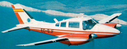
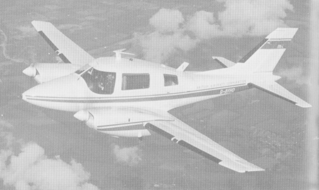
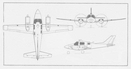
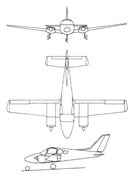
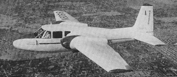
Twin-engined light transport aircraft with accommodation for five to eight persons. The first prototype flew on 15 August 1961, powered by Continental 194kW IO-470-A engines. The second prototype had increased dimensions and two 231kW Rolls-Royce/Continental GIO-470-As.
The initial commercial version was the B.206 Series I or B.206C. Early aircraft have overwing cabin door, later aircraft a passenger / cargo door aft of wings.
The B.206R was the military production version, ordered for communications and ferrying duties with the RAF under the name Basset CC.l. The B.206-S was a development of the Series I with supercharged engines and other refinements, first flying on 27 January 1966.
The B.206 Series II (B.206S) was development, with later production aircraft featuring an extended cabin, additional rear window on each side, and larger passenger / cargo door at rear on port side.
B.206 Srs II
Deliveries included two ambulance models for the Royal Flying Doctor Service of New South Wales, Australia.
By the close of 1969 40 B.206 Series I and II aircraft, 20 Bassets and two B.206Z pre-production types for the Ministry of Technology had been delivered.
The B.206 Series III developed version, seating 10 passengers, with dorsal and ventral fins, small tabs on main fin, extended tailplane trailing edge. A prototype only was built.
Beagle B.206 Srs.I / B.206C Powerplant: 2 x Rolls-Royce Continental GIO-470-A, 310 bhp take-off power (ISA SL) Propeller: McCauley two-blade constant speed fully feathering metal. Span, 45 ft 9 in Length 33 ft 8 in Height, 11 ft 4 in Gross wing area, 214 sq.ft Max. usable floor area, 44 sq.ft Max. usable cabin volume, 221 cu.ft Max. cabin length, 14 ft Max. width, 62 in Max. height, 50 in Accommodation: 6-8. Baggage space: 14 cu.ft Basic operational (gross less usable fuel and payload) wt, 4650 lb Total fuel, 1368 lb Max. take-off weight, 7500 lb Max. landing, 7125 lb Max. payload (volume limited), 1530 lb Max. zero fuel, 7050 lb Power loading (max. take-off weight), 12.1 lb/bhp Wing loading (max. take-off weight, 35.0 lb/sq.ft Wing loading (max. landing weight), 33.3 lb/sq.ft High-speed cruise, 184 kt. at 8 000 ft Long-range cruise, 160 kt. at 8 000 ft Approach speed 87 kt. EAS Take-off field length, ISA SL, 2,370 ft Landing field length, ISA at sea level; 2290 ft Range with allowances, max. fuel, 1482 lb payload, 1440 nm
Engines: 2 x RR/Cont. GIO-470, 230kW Take-off weight: 3223 kg / 7106 lb Empty weight: 1978 kg / 4361 lb Wingspan: 13.9 m / 45 ft 7 in Length: 10.3 m / 33 ft 10 in Height: 3.4 m / 11 ft 2 in Wing area: 19.9 sq.m / 214.20 sq ft Max. speed: 352 km/h / 219 mph Cruise speed: 348 km/h / 216 mph Ceiling: 6210 m / 20350 ft Range: 1500 km / 932 miles Range w/max.fuel: 3000 km / 1864 miles Range w/max.payload: 1850 km / 1150 miles Crew: 1 Passengers: 4-7
Engines: 2 x RR/Cont. GIO-470, 230kW Take-off weight: 3223 kg / 7106 lb Empty weight: 1978 kg / 4361 lb Wingspan: 13.9 m / 45 ft 7 in Length: 10.3 m / 33 ft 10 in Height: 3.4 m / 11 ft 2 in Wing area: 19.9 sq.m / 214.20 sq ft Max. speed: 352 km/h / 219 mph Cruise speed: 348 km/h / 216 mph Ceiling: 6210 m / 20350 ft Range: 1500 km / 932 miles Range w/max.fuel: 3000 km / 1864 miles Range w/max.payload: 1850 km / 1150 miles
B.206 Srs.II / B.206S Powerplant: two Rolls-Royce Continental GTSIO-520C, 340 bhp take-off power (ISA SL) Propeller: McCauley three-blade 7 ft 6 in diameter Wing span: 45 ft 9.5 in (13.96 m). Length: 33 ft 8 in (10.26 m) Height: 11 ft 3 in (3.43 m). Gross wing area, 214 sq.ft Max. usable floor area, 44 sq.ft Max. usable cabin volume, 196.5 cu.ft / 5.56 cu.m Max. cabin length, 11 ft 11 in / 3.63 m Max. width, 62 in / 1.57 m Max. height, 52 in. / 1.32 m Accommodation: 6-8. Baggage space: 21 cu.ft / 0.59 cu.m Basic empty weight, 4800 lb / 2177 kg Total fuel, 1386 lb Max. take-off weight, 7500 lb (3401 kg) Max. landing weight, 7125 lb Max. payload (volume limited), 1500 lb Max. zero fuel, 7000 1b Power loading (max. take-off weight), 11.02 lb/bhp Wing loading (max. take-off weight), 35.2 lb/sq.ft Wing loading (max. landing weight), 35.2 lb/sq.ft. Max level speed: 258 mph (415 kph). High-speed cruise 75%: 189 kt / 218 mph / 351 kph at 8000 ft Long-range cruise, 176 kt. at 8000 ft Approach speed 89 kt. EAS ROC SL MAUW 1340 fpm / 408 m/min Service ceiling: 27,100 ft / 8260 m Take-off field length, ISA SL, 2380 ft Landing field length, ISA at sea level, 2390 ft Range with allowances, max. fuel, 1060 lb payload: 1389 nm / 1600 mi / 2570 km Seats: 5-8
B.206 Srs.III Passenger capacity: 10 Prototype only
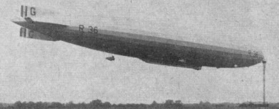
R36 was a British airship designed during World War I by the new Airship Design Department, work commencing in November 1917. She was a lengthened version of the R33 class. These had been influenced by the design of the German Zeppelin LZ 76 that had been forced to land in England. The LZ 96, which was forced down at Bourbonne-les-Bains in June 1917, provided yet more input into the design.
The R36, along with a second ship the R37 were to be a stretched version of the R33, getting more lift by adding another 33 feet (10 m) gas bag. Two of her five engines were German Maybach engines, recovered from the downed LZ 113. Construction began before the end of the war, but the design was altered to include accommodation for 50 passengers.
Unlike the R33 class, the control car was not suspended below the hull but directly attached to it, and formed the forward section of the elongated passenger compartment. The engines were housed in five engine cars, one pair (containing the Maybach engines) either side of the hull forward of the control car, a second pair either side of the passenger compartment and the fifth on the centreline in front of the tail surfaces. Unlike previous British airship designs, the fins and horizontal stabilisers were cantilevered structures, with no external bracing.
R36 was launched for her maiden flight on 1 April 1921 from the Beardmore works at Inchinnan near Glasgow. Late the following day she flew on to RNAS Pulham in Norfolk. When she first flew in 1921, it was not in her originally intended role as a patrol aircraft for the Royal Navy, but as an airliner, the first airship to carry a civil registration (G-FAAF).
On 5 April it left Pulham at 07:25am bound for London. After making its appearance over the city it proceeded to Salisbury Plain, where it climbed to 6,000 ft (1800 m) and began manoeuvring trials. Starting a fast turn of 130 degrees it encountered windshear, which overstressed the rudder, damaging the top rudder and starboard elevator. This made the ship adopt a nose down attitude and rapidly lose height, but it was brought under control at around 3,000 feet. Emergency repairs were made to the damaged control surfaces and the ship limped home on her one remaining rudder and elevator, using differential engine control to help with directional control, reaching Pulham at 9.15pm.
After repairs and strengthening work she re-emerged in June for a successful series of test flights, including an endurance trial starting on 10 June which lasted nearly 30 hours, covering 734 miles (1,174 km) over land and sea. She was also used by the Metropolitan Police for observing traffic congestion caused by the Ascot Races. Journalists and senior police representatives were entertained in great comfort on the day, and the journalists stories were dropped by parachute over Croydon airfield.
On 21 June, returning from another trial flight, she suffered damage during landing. The release of emergency ballast caused a sharp pitching up, straining the ship against the mooring line. The nearest unoccupied sheds were at Howden in Yorkshire since the Pulham sheds were holding German Zeppelins handed over as war reparations. The wind increased and it was decided that the LZ 109 (L 64) would have to be sacrificed to save the R36. Within 4 hours L 64 had been cut into pieces and cleared to give enough room for R36. Even then she was damaged by a gust of wind during the manoeuvre into the shed.
Repairs were delayed while policy on airships was reviewed because of the R38 disaster and economic conditions. In 1925 she was refurbished for an experimental flight to Egypt as part of the Imperial Airship Scheme, but calculations cast doubt on her ability to make the trip and in the light of her age and condition she was scrapped in 1926.
Engines: 3 × Sunbeam Cossack, 350 hp (260 kW) each / 2 × Maybach, 260 hp (190 kW) each Volume: 2,101,000 ft3 (59,500 m3) Length: 675 ft 0 in (206 m) Diameter: 78 ft 6 in (23.9 m) Height: 91 ft 7 in Maximum speed: 65 mph (105 km/h) Range: longest flight, 734 miles (1181 km) Endurance: 29 hours 54 min Service ceiling: highest attained, 6000 ft (1829 m) Crew: 28 Capacity: 50 passengers
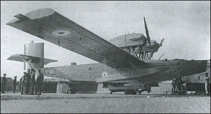
The Inverness is the Rohrbach RoIV all-metal flying boat designed by Adolf Rohrbach. The first aircraft (N183)was built in the Rohrbach factory in Denmark from parts manufactured in Berlin before being sent to Beardmore. The second aircraft (N184) was built by Beardmore.Both aircraft had short lives and were scrapped in 1925. The Inverness was equipped with two large masts and sails to get it home in the event of a forced water landing.
Paul Baumgarti was an Austrian who had worked on three helicopter designs during the war years before emigrating to Brazil. He experimented with a number of light helicopters in the 1950s and 1960s including the PB-64 which was an ultra-light single-seater with a minimal tubular fuselage structure.
The PB-64 had a pulse-jet propulsion arrangement with the two 13-kg ITA jets fitted to a transverse stabilising beam set at right angles to the rotor. The aircraft had no tail rotor but was fitted with a small, stainless steel, rudder. The blades have no taper or twist.
No production of any of these designs was undertaken.
Power: 2 x ITA pulse jet, 30 lb thrust Rotor dia: 21 ft 0 in Blade section: NACA 23012 Blade chord: 6.5 in Length: 15 ft 0 in Height: 7 ft 6 in Empty weight: 240 lb MAUW: 700 lb Max speed: 80 mph
The Bauman B-250 Brigadier prototype first flew in June 1947.
The production aircraft were designated Model 290 differed from the B-250 only in having higher power engines. Pilot production commenced in 1951 and the type certificate was received in 1952.
The Piper PA-21 factory designation was applied to a 1949 purchased Baumann B-250 Brigadier NX/N30025 c/n 1 to be used for evaluation. Piper acquired rights with a stipulation agreeing not to manufacture the design, or any variant of it, with pusher engines—Baumann retained those rights. Wings were redesigned for tractor engines in late 1949, but the project was cancelled when completion was judged as financially impractical. The plane went to a local school instead.
B-250
B-290 Engines: 2 x 145 hp Continental C145 Wingspan: 41 ft Wing area: 207 sq.ft Length: 27 ft 5 in Height: 10 ft 4 in Empty weight: 2150 lb Loaded weight: 2150 lb Max speed: 190 mph Cruise: 165 mph ROC: 1200 fpm Seats: 5
A team led by Roberto Oros di Bartini, a communist who had left fascist Italy for the USSR, presented in 1955 the project of a supersonic flying A-55 medium-range bomber boat. After the comprehensive development and improvement of this project, Bartini approached the creation of an amphibian vertical take-off and landing (SVVP in its Russian acronym).
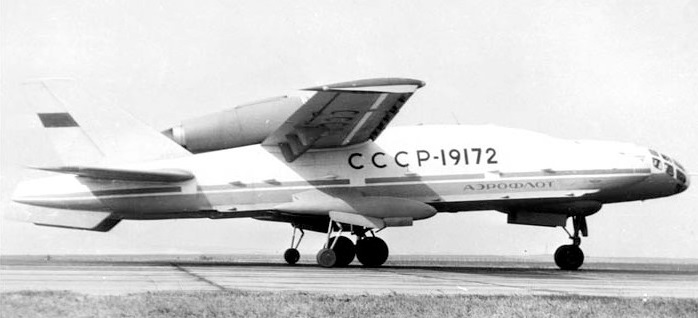
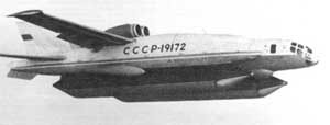
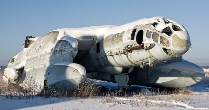
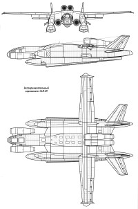
The experimental vertical take-off and landing amphibian VVA-14 (In Russian: ВВА-14) was characterized by the originality of its design and both its size and its take-off weight surpassed all VTOL aircraft built or projected at the time.
The VVA-14 antisubmarine amphibian began to be developed by government resolution in November 1965 at the UVZ helicopter factory (УВЗ – Ухтомскый Вертолетный Завод) and later transferred to Beriev’s OKB in Taganrog which was later would become the Taganrog Aviation Scientific-Technical Complex (TANTK).
In the process of development of the VVA-14 in the UVZ, together with Bartini participated the helicopter manufacturer VI Biriulin and the later general constructor MP Símonov. In the TANTK NA Pogorielov and GS Panatov were added, who would also later become general constructor. The main objective of the project was to develop new aerial means to combat missile-armed submarines, so it was decided, based on the experimental results, to create an amphibious anti-submarine device capable of detecting, tracking and destroying submarines, both on the surface and while submerged. This requirement demanded an autonomy of 4 hours of flight over an area located 500 km from the base. The development of search and rescue missions was established as a secondary objective.
After the analysis, a conceptual scheme based on the SVVP-2500 design was decided. It was a catamaran-like structure with a rectangular centroplane and a central fuselage in which 12 turbojets were located designed to achieve lift force in vertical take-off. Above the centerplane were two two-stage turbojets for horizontal flight. So-called PVPUs (пневматическое взлетно-посадочное устройство – pneumatic equipment for take-off and landing) were used for landing and take-off operations on water. This unusual composition and the great technical difficulties that arose made it necessary to incorporate researchers and engineers from TsAGI into the development., LII, TsIAM, VIAM and NIAT.
It was decided to develop two prototypes: the VVA-14-1M destined to carry out the functional tests of the selected composition in the different operating regimes and the VVA-14-2M to carry out the vertical take-off and landing tests and the processes transition to horizontal flight.
In the late 50s – early 60s, he created the SVVP-2500 vehicle with a take-off weight of 2500 tons in the form of a flying wing with a square center-section and consoles and a power plant made from lifting and cruising engines. In June 1972, the construction of the VVA-14-1M was completed, which did not include the vertical thrust engines and the floats. In July at the TANTK aerodrome, test runs of the prototype began, which was equipped with wheeled landing gear and on September 4 the first flight with pilot Yu took place. M. Kuprianov at the controls and LF Kusnietsov as a navigator. The flight tests that were carried out until June 1975 with a total of 107 flights with a total duration of 103 hours, reaching a maximum speed of 260 km / h.
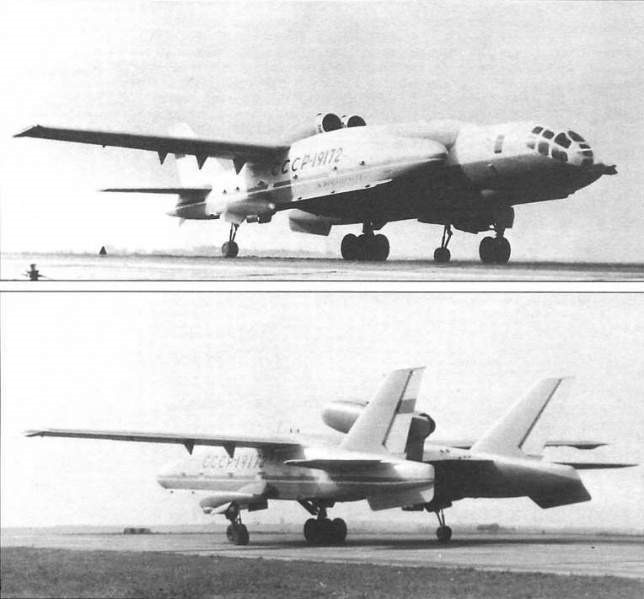
The VVA-14 was built as a cantilever high wing structure with a supporting centerplane and consoles to which the tailplanes and vertical fins were attached. These cigar-shaped gondolas were designed to contain the PVPU floats. The construction was made fundamentally of aluminum alloys and cadmium steel with anticorrosive coating in attention to the marine operation.
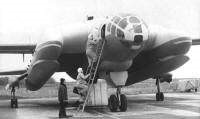
The fuselage was of semi-monocoque construction and was fused with the centroplane to achieve a supporting fuselage. In the bow was located the cockpit for a crew of three. This cabin could be detached from the fuselage in an emergency and ensured the life of the crew without the need for ejection seats.
Behind the cockpit was located the lift engine module consisting of 12 Kolosov RD-36-35PR (РД-36-35PR) turbojets and the weapons bay.
The wing was composed of the rectangular-shaped centroplane and the outer sections called OChK of trapezoidal shape with a positive dihedral of 2º. These sections featured flaps along the entire trailing edge, ailerons and flaps.
The tail planes were of the cantilever type with a sag of 40º at the leading edge and a surface area of 21.8 m². The elevator had an area of 6.33 m². The two vertical surfaces had a total area of 22.75 m² with a sag of 54º. The area of the rudders was 6.75 m².
The PVPUs (Pneumatic Takeoff and Landing Equipment) were made up of floats 14 meters long, 2.5 meters in diameter and a volume of 50 m3 made up of 12 sections. For its extension and retraction, a complex mechanical-hydro-pneumatic-electric system was used with 12 cylindrical injectors (one for each section). The air for filling was supplied by the compressors of the driving engines. A retractable tricycle landing gear was designed to transport the aircraft over land, with the front landing gear fixed to the fuselage and the main landing gear located on the inner surface of the nacelles. Each undercarriage mounted two wheels.
The combined powerplant consisted of two Soloviov D-30M double-contour turbojets with a thrust of 6800 kg for horizontal flight, located next to each other on separate consoles on the rear of the centerplane and 12 Kolosov RD-36 ascending turbojets. 35PR of 4400 kg each located in pairs with a certain forward inclination in the space of the fuselage behind the cockpit. At the top, an upward opening hatch for each pair of engines covered the air intakes. At the bottom were the nozzles with an adjustable angle of incidence. The use of an auxiliary turbocharged engine was assessed during the project.
The fuel system consisted of 14 tanks for a total capacity of 15,500 liters. A refuelling system at sea was devised.
The steering system of the aerodynamic surfaces was conventional, but in the case of vertical operations and the regime of transition to horizontal flight, 12 additional levers operated in pairs were conceived that allowed the control of the compressed air of the lift engines. The autopilot system allowed course control in all flight regimes.
The flight surfaces had a hot air anti-freeze system and the engines had a fire protection system.
The crew cabin had an oxygen and air conditioning system. An automatic stabilization system was designed to be used during vertical take-off and landing operations and horizontal flight in adverse weather conditions. In the search and rescue version, the VVA-14 was also designed with radio marking systems. The antisubmarine version had to use a Burevietnik search system capable of locating enemy submarines and coordinating the data necessary for their destruction. To detect the submarines, it was planned to equip the VVA-14 with 144 RGB-1U hydroacoustic buoys (РГБ-1У) and up to 100 noise generators, in addition to a Bor-1 magnetic anomaly detector. (Бор-1).
The armament for the antisubmarine version would be located in a hold in the fuselage with a capacity for 2000 kg, being able to incorporate two naval torpedoes or eight IGMD-500 aviation mines (ИГМД-500) or 16 PLAB-250 aviation bombs (ПЛАБ-250). The use of a survival system equipped with active and passive interference launchers was also designed.
In 1974 they settled the VVA-14-1M the PVPU developed at the Bureau of Construction Aggregates of Dolgoprudniencsky and produced in Yaroslavsk, with two large inflatable floats deployed at the bottom of the gondolas. The tests began on June 11, 1975 and included the inflation and collection of the PVPU, which showed that the operation was quite complex and the solution still had to be worked on.
Between 1974 and 1975, 106 cycles of expansion and collection of the PVPU were carried out of which 11 were carried out in flight, both from the water and from the ground.
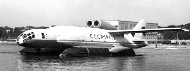
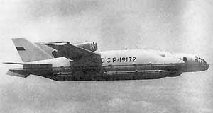
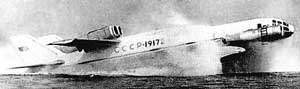
VVA-14 in flight with floats
Flight tests confirmed the calculations and showed that at the bottom of the 10.75-meter chord centroplane an effective air cushion was formed at 10 – 12 meters high during landing and at 8 meters the cushion was so dense that test pilot Yu. M. Kuprianov on more than one occasion asked to be allowed to release the controls so that the machine would settle on its own.
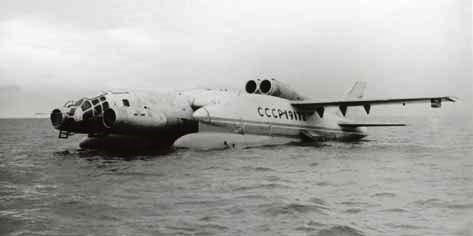
VVA-14 in flight with the floats extended.
The VVA-14 never made the vertical take-off and landing. The engines for this purpose were never ready. The VVA-14-1M was modified with the installation in the bow of two Soloviov D-30M engines destined to blow and create the air cushion under the centerplane, using the aircraft as an ekranoplane. Among the main modifications made, the inflatable floats were replaced by metallic ones. This model received the designation 14M-1P and was successfully tested in 1976 on the Taganrog peninsula in the Sea of Azov.
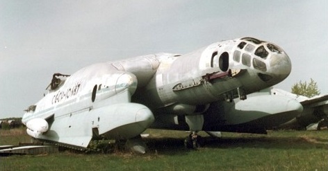
Today the remains of this project are preserved in the VVS Museum of Mónino.
VVA-14 Powerplant: two Soloviov D-30M double-contour turbojets, 6,800 kg and 12 Kolosov RD-36-35PR, 4,400 kg Wingspan: 30.00 m Wing area: 21.77 m² Length: 25.97 m Height: 6.79 m Empty weight: 35356 kg Maximum takeoff weight: 52,000 kg Fuel weight: 14000 kg Normal military load: 2000 kg Maximum military load: 4000 kg Maximum speed: 760km / h Cruising speed: 640 km / h Patrol speed: 360 km / h Practical range: 2450 km Practical ceiling: 8000-10000 m Armament: 2 x naval torpedoes / 8 x IGMD-500 aviation mines (ИГМД-500) or 16 PLAB-250 bombs (ПЛАБ-250) Accommodation: 3 crew
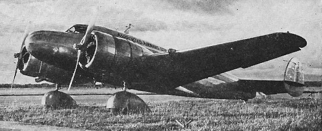
Military version by V.G.Ermolaev. First flown June 1940. 128 were built to July’41. All metal midwinger with “inverted seagull” wing, twin-tail. 3-wheel gear with tail wheel.
Versions:
Er-2 2xAM-35, april 1942.
Er-2 2xACh-30B, december 1943, 300 were built. 3 x 1000kg bombs. Max speed 446km/h. Range 5000km.
Engines: 2 x Klimov M-105, 1050hp Max speed 491 km/h. Practical ceiling 7000 m. Range 4000 km. Empty weight 6500 kg. Max takeoff weight 11920 kg. Wing span 23m. Length 16.34m. Wing area 72 sq.m. Armament One 12.7 mm machinegun “UBT” + two 7.62mm ShKAS, up to 1000kg bombs. Seats 4.
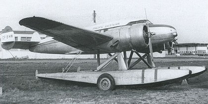
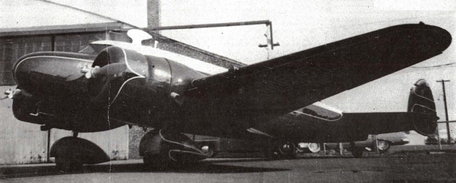
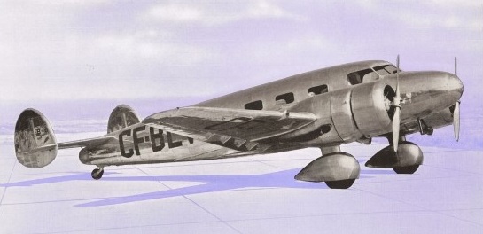
This aircraft was built in a small hanger at the Detroit City Airport, Michign, and operated in the Canadian north into the sixties. It was a flexable aircraft for the bush as it could operate on wheels, skis or floats. The pictured plane was Canadian registered and operated by Pacific Western Airlines.
Barkley-Grow NC18388 sn.1
Barkley-Grow T8P-1 CF-BLV 1938
The design incorporated a multispar stressed-skin wing with two X-spars patented by A. S. Barkley (US patent #2,122,709 to Barkley in 1938) that eliminated the need for ribs or bulkheads in the wing.
The initial example made its first flight in April 1937, piloted by Frank Cordova.
After a series of demonstration flights, the prototype went to Canada where it was registered CF-BVE.
Canadian Car & Foundry obtained the world-wide distributing rights for all but the United States.
Only 11 T8P-1s were constructed. Canadian Car demonstrated the aircraft to the Department of Defence but apart from selling only one aircraft to the RCAF, no government orders were obtained. The RCAF preferred the Beech 18.
Receiving ATC 662 and priced at $37,500, those built include prototype NX18388=CF-BVE=NC18388, NC18470, NX26400=CF-BQM, NC26496=CF-BTX, YRAHA=OB-GGK, CF-BLV, CF-BMG, CF-BMV, CF-BMW, some on twin EDO floats.
As a robust aircraft, three T8P-1 survived into the late 1960s.
Through the purchase of Yukon Southen Air Transport, Mackenzie Air Service and Prairie Airways, CPAL acquired a total of six Barkley-Grows.
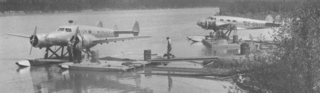
The prototype aircraft, CF-BVE, was sold in 1945 and BMG and BTX were written off. CF-BLV, BMV, BMW and BQM served until late 1949/early 1950 when replaced by more modern aircraft.
CF-BTX and CF-BMW
CF-BQM was being restored at the Aeo Space Museum in Calgary, Canada.
T8P-1 Engine: Pratt & Whitney Junior, 400 hp Wingspan: 50 ft 8 in Length: 36 ft 2 in Height: 9 ft 7.5 in Empty weight: 5880 lb Loaded weight: 8750 lb Max speed: 220 mph at 5000 ft Cruise: 185 mph at 10,000 ft ROC: 1400 fpm Cruise range: 1000 mi Crew: 2 Passengers: 8
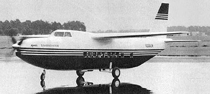
The 1996 LM200 Loadmaster was designed for Federal Express, featuring two turboshafts driving one five-bladed propeller through a combining gearbox. It was design-driven for need to carry four “demi” containers.
Engine: 2 x Allied Signal / Allison TWINPAC CTP 800-4T, 2367 shp Length: 68.996 ft / 21.03 m Height: 22.474 ft / 6.85 m Wingspan: 63.976 ft / 19.5 m Wing area: 453.487 sq.ft / 42.13 sq.m Max take off weight: 19002.7 lb / 8618.0 kg Weight empty: 9000.8 lb / 4082.0 kg Max. speed: 196 kts / 363 km/h Cruising speed: 165 kts / 306 km/h Initial climb rate: 1870.08 ft/min / 9.5 m/s Wing load: 42.03 lb/sq.ft / 205.0 kg/sq.m Maximum range: 1120 nm / 2075 km Range (max. weight): 651 nm / 1205 km Crew: 2 Payload: 19-34pax / max. 3400kg
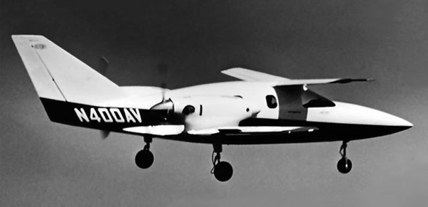
The Avtek 400 was the proof of concept aircraft of a six/nine-seat pusher turboprop-powered business aircraft, with a crew of one or two pilots. Designed by Leo J Windecker, it was the first US aircraft constructed throughout from DuPont ‘Kevlar’ advanced composite material, hence the ‘DUPONT’ logo on upper sides of the tailfin.
It featured over the wing pusher propellers, high mounted forward canard, bizarre wing shapes, all-Kevlar construction and lack of elevators.
First flown in the USA on 17 September 1984, the type never went into production, and the company went bankrupt in 1998.
The aircraft appeared in the ‘Airwolf’ TV series as the X-400, the plane used by the villain Lou Stappleford in the episode ‘Eagles’.”
400A Engines: 2 x 680hp P&W Canada PT6A-3L/R Wingspan: 35’0″ Length: 39’4″ Useful load: 2781 lb Max speed: 294 mph Stall: 96 mph Range: 2600 mi Ceiling: 41,000 Seats: 6-10