Bell / Agusta BA 609

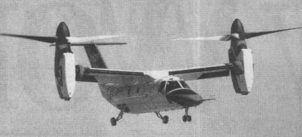
Bell and Boeing revealed in February 1996 that studies were in progress for a nine-passenger civil tiltrotor aircraft in the 6,350kg weight class, with the preliminary designation D-600. On 18 November 1996, the two companies announced that a joint venture was being established to design, develop, certify and market a six- to nine-passenger civil tiltrotor as the Bell Boeing 609. The machine has engines which pivot 90 degrees so it can take off vertically like a helicopter, then fly horizontally like a plane.
Boeing withdrew as a partner on 1 March 1998 and Bell formally announced at the Farnborough Air Show in September 1998 that they had teamed with Agusta. Agusta was investing and participating in BA609 development and was to be responsible for assembly of BA609s sold in Europe and elsewhere.
Preliminary design review completed May 1997. Manufacture of parts for the prototypes began in Philadelphia, August 1997, and a full-size mockup was exhibited at the Paris Air Show in June 1997.
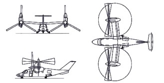
With a T-tail configuration and composite cross-shafts to keep both prop rotors turning in event of engine failure. Manual screwjack facility exists whereby the prop-rotors can be tilted into helicopter mode if the cross-shafts fail. Designed using three-dimensional CATIA digital computer design system, the airframe has design life of 20,000 flight hours.
The aluminium fuselage structure has composites skinning and composites wings. The undercarriage is a retractable tricycle type, with twin nosewheels and single wheel on each-main unit.
Control is by a BAB Systems triplex digital fly-by-wire flight control system, with Dowty Aerospace actuators. The T tail has conventional elevators and no rudder. Two-segment trailing-edge flaperons are fitted.
Two 1,447kW Pratt & Whitney Canada PT6C-G7A turboshaft enginesc are installed in tilting nacelles at the wingtips, each driving a three-blade proprotor. Nacelle transition is achieved in 20 seconds. Fuel is in integral wing tanks with a usable capacity of 1,401 litres, and provision for auxiliary fuel tanks.
The airframe carries a crew of two, side by side on flight deck, with dual controls, and a maximum of nine passengers in the standard aircraft. A crew and passenger door is on the starboard side, forward of wing. The cockpit is pressurised and air conditioned; pressurisation differential 0.38 bar.
Ground-running trials began on 6 December 2002 and the first flight of the prototype (N609TR) took place (in the vertical mode only) on 7 March 2003 in Arlington, Texas, rescheduled from late 2002. The Bell/Augusta Aerospace Co said its BA 609 tilt-rotor aircraft flew at an altitude of about 15m in its first test flight.
Four prototypes were produced for a 36-month flight test programme leading to certification in January 2007 under FAR Pt 25 (fixed-wing aircraft) and Pt 29 (helicopters), plus Pt 21.17(b) Special Conditions for unique components. The first prototype were used primarily for expansion of flight envelope, while the second, third and fourth airframes were dedicated to systems certification, avionics and icing approval, and FAA function and reliability, respectively.

Leonardo AW609

The order book opened on the 2nd of February 1997 at Heli Expo, with the first order placed soon after by an unspecified customer. A total of 70 were ordered by 40 customers in 18 countries by March 2003. A briefing was given to the US Coast Guard, late 1997, followed by a demonstration by the XV-15 tiltrotor concept demonstrator aboard the Coast Guard cutter Mohawk off Key West, Florida, in May 1999.
In 1998 Bell Helicopter Textron acquired Boeing’s 49% interest in the Bell-Boeing 609 civil tiltrotor and has assumed full ownership.

Bell 609
Engine: 2 x Pratt & Whitney PT6C-67A, 1360kW / 1850hp
Empty weight: 6300kg
Max speed: 510km/h
Range: 1390km
Crew: 2
Passengers: 6-9

Bell X-14

The Bell X-14 was produced as a vertical take-off prototype and achieved its first hovering flight on 17 February l957. The X-14 was originally created to explore the feasibility of operating a VTOL aircraft from a normal pilot station using standard flight instruments and references. Of equal importance, the X-14 was to demonstrate various VTOL systems and engine technologies—the aircraft was the first to demonstrate the concept of using vectored jet thrust as the only power system.
The airframe was as simple and light as possible, and was characterized by an open cockpit and fixed tailwheel landing gear. In its original form the aeroplane was powered by a pair of Bristol Siddeley Viper turbojets located side-by-side in the extreme nose of the aeroplane exhausting via nozzles on the sides of the aeroplane on the centre of gravity. For vertical take-off the nozzles were vectored directly downward, and for transition into forward flight were vectored gradually aft. The first successful transition was accomplished in May 1958, and the aeroplane was later re-engined with General Electric J85 turbojets. The X-14 made its last flight on 29 May 1981.
The X-14 successfully demonstrated that the concept of vectored jet thrust was viable, as subsequently used on the BAe/McDonnell Douglas Harrier. Flight tests using the X-14’s variable stability control system resulted in major contributions to the understanding of V/STOL handling characteristics. The X-14 also proved useful as a testbed for various unique V/STOL concepts, such as NASA’s direct side-force maneuvering system.
Over 25 pilots from around the world “previewed” V/STOL handling qualities in the X-14 prior to making test flights in other V/STOL designs. The single X-14 continued flying for nearly a quarter century before being retired to the Army Aviation Museum at Fort Rucker, Alabama. It is currently in storage at a private collection in Indiana.

Fastest Flight: 172 mph
Highest Flight: 18,000 feet (approx)

Bell 65 VTOL

The Bell 65 VTOL was built to test the practicability of rotatable turbojets providing thrust for both lift and forward propulsion. Two turbojets, which raised it off the ground for take-off, could be turned 90 degrees in the air to provide forward thrust, leaving the fixed wing to provide lift.

Bell 65 VTOL Article

Constructed largely from existing parts, power was provided by two 1000 lb thrust Fairchild J44 turbojets and one Continental-Turbomeca Palouste compressor.

Control at low-speed being obtained from compressed-air jets at the tail and wingtips fed by the Palouste.

Engines: two x 1000 lb thrust Fairchild J44 turbojet
Wingspan: 26 ft
Wing area: 130 sq.ft approx.
Length: 21 ft
Loaded weight: 2200 lb approx.

Bell XP-83

Bell’s last fighter, designed to replace the P-51, was the long range single seat XP-83.
On 24 March 1944 the USAAF tasked Bell to build a larger, longer-range jet fighter to superceed the P-51 Mustang. Bell assigned engineer Charles Rhodes to develop the XP-83, powered by two 1633kg thrust General Electric 1-40 (later J33-GE-5) turbojets, and to be armed with six 12.7mm Browning nose machine-guns.
First flown on 25 February 1945, the first XP-83 proved underpowered and unstable. The close proximity of the two low-slung powerplants caused hot exhaust gases to buckle the tail-plane unless, during run-ups, fire trucks were used to play streams of water over the rear fuselage.

The second XP-83 was completed with a slightly different bubble canopy and extended nose to accommodate six 15.2mm guns, the increase in barrel diameter being based on anticipated firepower needs for the planned amphibious invasion of Japan. This airframe was used in gunnery tests at Wright Field, Ohio.
Modified tailpipes, angled outwards, resolved the heat/buckling problem. Wind tunnel tests showed than a 45.7mm extension of the vertical tail would assure stability, though it is not clear whether this modification was actually made.
Except range, which was 3540km with underwing drop-tanks, the Bell XP-83 offered no improvement over the Lockheed F-80 Shooting Star then in production. For the post-war fighter-escort role, the newly independent USAF turned to the North American F-82 Twin Mustang. The redesignated XF-83 operated as a flying testbed for new technology.
The first XP-83 was assigned to a ramjet engine test programme. A hatch was cut in the belly to provide entry into the aft fuselage and an engineer’s station with a small port-side window, was created behind the pilot. Experimental ramjets were slung under the wings. The intent was for the XF-83 to serve as a proving vehicle for ramjet power, once aloft flying with the ramjets alone.
On 4 September 1947, just as this test programme had begun, a ramjet caught fire and flames spread to the wing. Pilot Chalmers ‘Slick’ Goodlin and engineer Charles Fay, without benefit of ejection seats, bailed out safely and the XF-83 was destroyed.

XF-83
Engines: 2 x General Electric J33-GE-5, 1814kg
Max take-off weight: 10927 kg / 24090 lb
Empty weight: 6398 kg / 14105 lb
Wingspan: 16.15 m / 52 ft 12 in
Length: 13.66 m / 44 ft 10 in
Height: 4.65 m / 15 ft 3 in
Wing area: 40.04 sq.m / 430.99 sq ft
Max. speed: 840 km/h / 522 mph
Ceiling: 13715 m / 45000 ft
Range w/max.fuel: 2784 km / 1730 miles
Crew: 1
Armament: 6 x 12.7mm machine-guns

Bell P-59 Airacomet

The XP59 Airacomet project was launched by USAF Major General Henry (Hap), Arnold on the 5th September 1941 began when he approached Bell Aircraft and asked them to build a new fighter based around the GE-1, a license made Whittle W2/B engine. The contract was signed on the 30th September with a deadline of eight months to produce the first of three prototypes designated XP-59A’s.

The Bell designers adopted a conventional approach which resulted in a preliminary design in just two months. This was approved and construction of the first prototype started which was shipped to Muroc Dry Lake (Now Edwards Air Force base) on the 12th September 1942 for ground tests. The engines called GE-1’s were built at the same time by General Electric and had an initial thrust of 1,250 lbs. This meant that two engines were required and in the Airacomet these were mounted side by side in the fuselage.

Bell P-59 Article

XP-59A Airacomet

After being trucked out to Muroc Dry Lake, California, draped in tarpaulin with a fake propeller attached, the
Airacomet was first flown on the 1st October 1942 by Robert M. Stanley, chief test pilot for Bell aircraft, although the official first flight was recorded as the 2nd of October.

The Airacomet was kept secret and it was only announced to the public in 1943.

XP-59

Named Airacomet, 13 development YP-59A aircraft followed during 1943-4 with the more powerful General Electric 1-16 (131) turbojet, and these were used primarily to provide basic flight data on turbojets. Production orders for 20 P-59A aircraft with J31-GE-3 engines and 80 P-59B aircralt with J31-GE-5 engines were awarded but, as a result of successful development of the Lockheed P-80 Shooting Star the last 50 of the latter were cancelled as superfluous, All production had been completed by the end of the war and many of the aircraft were issued to a special USAAF unit, the 412th Fighter Group, for use as drones or drone controllers, some aircraft having a second open cockpit in the nose for an observer. No P-59 ever achieved operational status, being found to lack adequate performance.

One XP-59A, a trade for a Gloster Meteor flown by the USAAF, was evaluated briefly by the RAF at Farnborough and wore British markings. Three more were flown by the US Navy under the designation XF2L-1.

Gallery

Bell XP-59 Airacomet
Span: 45ft 6in (13.87m)
Length: 38ft 2in (11.63 m)
Height: 12ft 4in (3.76 m)
Powerplant: Two General Electric I-A’s (each 1,250lb (567kg) thrust)
Maximum speed: 404 mph
Weight: Empty 7,320lb (3,320 kg), Loaded 12,562lb (5,698 kg)
Armament: 2x 37mm cannons
Range: 400 miles

Bell P-59A Airacomet
Engines: 2 x General Electric I-A turbojet engines generating 2,800lbs of thrust each.
Length: 38.16ft (11.63m)
Width: 45.51ft (13.87m)
Height: 12.34ft (3.76m)
Maximum Speed: 413mph (664kmh; 359kts)
Maximum Range: 240miles (386km)
Rate-of-Climb: 3,200ft/min (975m/min)
Service Ceiling: 46,194ft (14,080m)
Armament: 1 x 37mm cannon, 3 x 12.7mm machine guns
Bombload: 2,000lbs.
Accommodation: 1
Hardpoints: 2
Empty Weight: 7,937lbs (3,600kg)
Maximum Take-Off Weight: 12,699lbs (5,760kg)

P-59B Airacomet
Type: single-seat interceptor fighter
Powerplant: two 907-kg (2,000-1b) thrust General Electric J31-GE-5 turbojets
Span 13.87 m (45 ft 6 in)
Length 11.62 m (38 ft 1.5 in)
Height 3.66 m (12 ft 0 in)
Wing area 35.84 sq.m (385.8 sq ft)
Maximum speed 658 km/h (409 mph) at 10670 m (35,000 ft)
Cruise speed: 560 km/h / 348 mph
Climb to 3050 m (10,000 ft) in 3 minutes 20 seconds
Service ceiling 14040 m (46,200 ft)
Range 644 km (400 miles)
Empty weight 3704 kg (8,165 lb)
Maximum take-off 6214 kg (13.700 lb)
Crew: 1
Armament: one 20-mm M4 cannon and three 12.7-mrn (0.5-in) machine-guns in the nose

Bell FM-1 Airacuda          

Designed by Robert J Woods, the FM-1 Airacuda was a five-seat long-range bomber destroyer powered by two engines mounted as pushers. The Airacuda accommodated two gunners in forward extensions of the engine nacelles, with access along wing crawlways to the fuselage in the event that it proved necessary to evacuate the nacelle gun positions.

Airacuda with Larry Bell (3rd from right)

Initially, Larry Bell envisioned his aircraft to fly 300 miles per hour at about 20,000 feet with turbosupercharged Allison engines. This was drastically cut when the Air Corps ordered a scaled-down Allison to be used instead with the reason being that the turbosupercharger proved quite volatile and explosive in the YFM-1 when tested. This effectively destroyed any performance the Airacuda could achieve, bring the ceiling down to 12,000 feet and a top speed barely reaching 270 miles per hour.

The Airacuda was built around the ability carry a 37mm cannon in each nacelle position, manned by a crewmember. Additional weaponry consisted of 2 x 12.7mm heavy caliber air-cooled machine guns and 2 x 7.62mm general purpose machine guns.

It was found that a considerable amount of smoke filled the nacelle crewmembers position when the 37mm cannon armament was fired.

The prototype, the XFM-1 powered by two 1150hp Allison V-1710-13 12-cylinder liquid-cooled engines driving three-blade propellers via 1.62m extension shafts, was flown on 1 September 1937. Twelve evaluation models were ordered, nine as YFM-1s and three as YFM-1As which differed in having tricycle undercarriages. Power was provided by 1,150hp Allison V-1710-23s, but three YFM-1s were completed with V-1710-41s of 1,090hp as YFM-1Bs. The 12 YFMs were delivered to the USAAC between February and October 1940, and their armament was one 37mm T-9 cannon with 110 rounds in each engine nacelle, one 7.62mm M-2 machine gun with 500 rounds in each of the retractable dorsal turret and ventral tunnel positions, and one 12.7mm M-2 gun firing from each of the port and starboard beam positions. Twenty 13.6kg bombs could be accommodated internally.

Despite the shortcomings – and at least two being lost to accidents – the Airacuda fielded one entire operational squadron though only operating in 1938 through 1940 and were eventually removed from service in 1942 – used as ground crew trainers. Beyond several photo opportunities across the country, the Airacuda never fulfilled its purpose of bomber-interceptor and destroyer and never would see combat action in the Second World War. All were eventually scrapped with only 1 prototype and 12 production models ever existing.

XFM-1 Airacuda
Engines: 2 x Allison V-1710-41, 1,150hp each.
Length: 44.85ft (13.67m)
Width: 69.85ft (21.29m)
Height: 13.58ft (4.14m)
Empty Weight: 13,375lbs (6,067kg)
Maximum Take-Off Weight: 17,333lbs (7,862kg)
Maximum Speed: 277mph (446kmh; 241kts)
Maximum Range: 2,600miles (4,184km)
Service Ceiling: 30,512ft (9,300m)
Armament:
2 x 12.7mm machine guns
2 x 7.62mm machine guns
2 x 37mm cannon
Bombload: 2 x 300lb
Crew: 5
Hardpoints: 2

YFM-1B
Take-off weight: 8618 kg / 19000 lb
Wingspan: 21.33 m / 69 ft 12 in
Length: 14.00 m / 45 ft 11 in
Height: 3.78 m / 12 ft 5 in
Wing area: 55.74 sq.m / 599.98 sq ft
Max. speed: 431 km/h / 268 mph
Range: 2687 km / 1670 miles
Crew: 5

Bellamy-Hilborne BH.1 Halcyon

The Bellamy Hillborne B.H.1 Halcyon was an all-wood four-seater with retractable nose wheel undercarriage, powered by two 105 h.p Walter Minor engines. Designed by R.J.Hillborne and built at Eastleigh by the Hampshire Aero Club under the direction of Vivian H.Bellamy 1960-61.

One aircraft only built: G-ARIO. C/n HAC.5., registered (C of R R7117/1) to Vivian H. Bellamy 30.1.61. Construction well advanced by May 1961 and engines run September 1961, but the project was abandoned when the aircraft was damaged during taxiing trials at Eastleigh Airport, Southampton, Hampshire 17.2.1962. Reportedly G-ARIO collided with Hampshire Aeroplane Club’s hangar and was wrecked.

The damage suffered in taxiing trials was severe, namely a fracture of the centre section rear spar which rendered the Halcyon beyond economic repair and thus the project was abandoned, the aeroplane was put into storage and eventually its remains were burned.

Despite this, the registration was not cancelled until eleven years later – on 13.9.73 – as P.W.F.U. (“Permanently Withdrawn From Use”)

Wingspan: 30.05 ft
Length: 23.0 ft

Beechcraft-SFERMA PD-146 Marquis

In 1962, the SFERMA (French Society for Maintenance and Repair of Aeronautical Equipment) modified a Model 95 Travel Air by fitting it with the swept tail units of the Model 55 “Baron” and by replacing the piston engines with two Astazou IIA turboprop of 440hp.

Seventeen Model 55 “Baron” cells are also re-engineered, including three for Beechcraft, and an eighteenth is not completed.

Beech-Sferma PD-146 60A Marquis F-BLLR

The PD-146 “Marquis” n°2 (F-BJSI) is re-engined with Astazou X 600hp turbines and established several world speed records in its category (C-1-d, Group 2):

On February 21, 1964, 1,000km at 502.12km / h (piloted by Maurice Oppeneau and Jacques Boisbeau).

On June 19, 1964, 2,000km at 446.92km / h (piloted by Maurice Oppeneau and Jacques Boisbeau).

SFERMA 60A Marquis