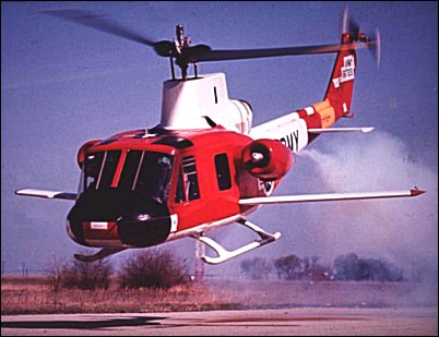
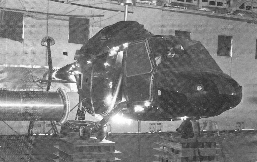
In 1959, the TRECOM (United States Army’s Transportation Research Command) set up a programme in order to determine various rotor systems and methods of drag reduction for helicopters. For this programme, Bell modified the first YH-40-BF service test model (s/n 56-6723) as a research test-bed which was known at Bell as the Model 533. Reworking was done on the airframe in order to reduce drag, including a cambered vertical tail surface to unload the tail rotor, streamlined fairing for the rotor head, flush air intakes located on each side of the new rotor fairing, redesigned cross-tubes for landing skids, and new hinges for the doors. The stabilising bar was removed and replaced by a variable-tilt rotor mast in order to maintain the fuselage in low-drag attitude. The 1400shp Lycoming T53-L-13 turboshaft was retained. Tests in NASA’s Ames wind tunnel showed that the aerodynamics of the airframe had been improved to such an extent that the equivalent flatplane area of the Huey had been reduced from 2.3sq.m to 1sq.m. Still with its original US Army serial number, the Model 533 made its maiden flight on Friday 10 August, 1962, and flight tests were conducted at Fort Worth in late 1962. In March 1963, the Model 533 flew at 278km/h and 302km/h was attained in a shallow dive. Several rotor types were tested (two-blade UH-1B-like rotor and rigid three-blade rotors) and two 765-kg Continental J69-T-9 turbojets were installed on each side of the fuselage. Take-off weight of the aircraft was now 3880kg. On 17 January, 1964, the helicopter achieved a speed of 338km/h in level flight using only 780shp from the 1100shp Lycoming T53-L-9A shaft-turbine, plus 568kg from the J69s. The next modification consisted of fitting two small sweptback fixed wings to convert the aircraft into a compound helicopter. On 11 May, 1964, it flew at 357km/h. The aircraft was then flown to San Antonio to have its J69-T-9s replaced by 765-kg J69-T-29s, and, on 15 October, 1964, the Model 533 was the first helicopter to break the 200 knots (370km/h) barrier by attaining 380km/h. On 6 April, 1965, the Model 533 flew at 402km/h in level flight and 409km/h in a shallow dive. It showed also its outstanding manoeuvrability in performing 2g turns and 60deg banks at speeds around 320km/h, and a Mach number of 0.985 was recorded by the advancing blades of the rotor. Early in 1968, a subsequent phase of the programme was the installation of two 1490-kg Pratt & Whitney JT12A-3 turbojets at the end of short stub wings. The first flight in this configuration was made in 1968, the machine gradually recording still higher speeds and, in May 1969, Bell announced that 508km/h had been attained.
Model 533 Rotor diameter: 13.41m Length of fuselage: 12.98m Normal take-off weight: 4173kg Maximum speed: 508km/h
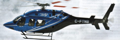
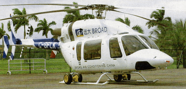
The Bell 429 was the first model designed from scratch, since the Bell 222. A light-medium twin helicopter which received certification from Transport Canada Civil Aviation and the FAA on 1 July 2009. Five prototypes were used during certification. The first delivery was on July 7, in Iowa.
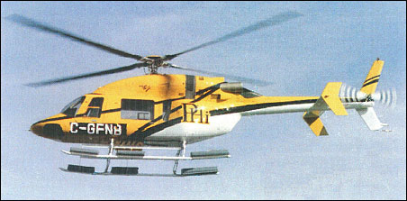
Launched as the New Light Twin (NLT) in February 1996 on signature of collaborative agreement with Samsung Aerospace Industries of South Korea. The Bell 427 prototype assembly began early 1997. An enlarged and lengthened by 13 inches version of Model 407 with wider cabin, centre-section fuel tank, OH-58D composite four-blade main rotor, and 2705kg TOGW, powered is from two 600shp Pratt & Whitney PW206D turboshafts. The first flight of the first prototype (C-GBLL) was on 11 December 1997 at Mirabel, Quebec. The second prototype (C-FCSS) was completed in February 1998 and the two prototypes undertook flight test programme, gaining Transport Canada certification on 19 November 1999, FAA VFR certification achieved in 24 January 2000, followed by Dual Pilot IFR (DPIFR) Category A certification on 24 May 2000. The first production aircraft (C-GDEJ) was flown in June 1998. Compared with prototypes, the production 427 has longer exhausts and revised upper surface contours. Similar in appearance to the Bell 407, with a cabin stretch of 33cm, the 427 is all-new design, incorporating twin-engine safety margins. Flight dynamics are based on the four-blade rotor system of Bell OH-58D Kiowa, allied to tail rotor of Bell 407, and folding main blades. A purpose-designed ‘flat pack’ main transmission, with direct input from both engines, has only four gear meshes to simplify design and operation. The transmission is attached to the airframe by four liquid-inertia vibration eliminators. It was the first Bell helicopter designed entirely with use of computer (Dassault CATIA programme).
The structure is generally as for the Bell 206, but extensive use of carbon/epoxy composites reduces airframe parts count by some 33%. Cabin floor and roof are flat panels for ease of manufacture; minimal use of curved panels elsewhere. Composites main and tail rotors; main blades have nickel-plated stainless steel leading-edges. Soft-in-plane hub of main rotor employs a composites flexbeam yoke and elastomeric joints, eliminating lubrication and maintenance requirements. Brake and main rotor blade folding optional. Composites cabins and rolled aluminium tailbooms built by Samsung; assembly in Canada, except for sales to Korea and China; Hexcel honeycomb as stiffener. The landing gear is twin skids with dynamically tuned cross tubes to reduce ground resonance. Low skids standard; optional high skids and emergency floats. Fuel is contained in three crash-resistant tanks; two forward, one aft, with a total usable capacity of 770 litres. One forward fuel tank can be removed in EMS configurations to provide additional stretcher space in cabin or to permit stretcher to extend into port side of cockpit. Oil capacity (total, both engines) 10.2 litres. Standard accommodation is for two crew in cockpit, on 20g energy-attenuating seats, and six passengers in cabin on two rows of three, seats in club configuration (all-forward-facing scats optional); all scats equipped with inertia-reel shoulder harnesses. Optional EMS interiors provide for carriage of one or two stretchers with up to two medical attendants, affording either full patient or head-only in-flight access, with single- or two-person crew. In cargo configuration, with all passenger seats removed, an optional removable flat cargo floor can be installed, equipped with integral tie-downs. Two forward-hinged doors each side; cabin doors, both sides, are forward-hinged, but port unit can be replaced by optional rearward-sliding door for cargo handling. External door on starboard side to rear baggage hold.
Orders for 22 were placed during the mockup’s first public display at Farnborough Air Show 1996, and 85 were on order by May 2000 from 50 customers. Deliveries began 2000 five delivered that year, 15 in 2001 and five in 2002.
Engines: Two Pratt & Whitney Canada PW207D turboshafts with FADEC, each 529kW for T-O (5 min) or 466kW max continuous OEI ratings: 611kW for 30 sec, 582kW for 2 min, 559kW for 30 min or 529kW max continuous. Twin-engine transmission rating: T-O & max continuous: 597kW. OEI transmission rating: 485kW for 30 sec: 451kW for 2 min; 343kW max continuous. Main rotor rpm: 395 Tail rotor rpm: 2,375 Main rotor diameter: 11.28m Fuselage length: 10.9m Take-off weight: 2722kg Empty weight: 1581kg Max speed at sea level: 252km/h Cruising speed at sea level: 240km/h Hovering ceiling, OGE: 4235m Hovering ceiling, IGE: 4940m Range at sea level: 663km Crew: 1 Passengers: 6-7
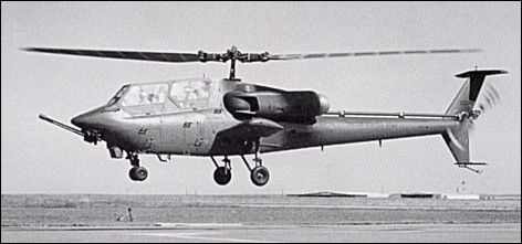
In November 1972 the Army called for design proposals for a new Advanced Attack Helicopter (AAH) intended for the all-weather anti-armor role. The Army’s specifications required that the aircraft be powered by twin General Electric T700 turboshaft engines and armed with up to sixteen Hellfire or TOW anti-tank missiles in addition to a single 30mm cannon. Preliminary design proposals were submitted by Boeing-Vertol, Bell, Hughes, Lockheed, and Sikorsky, and in June 1973 Bell and Hughes were selected as finalists and were each awarded contracts for the construction of two prototype aircraft. The contract was awarded to Bell on 22 June, 1973, for design, construction and qualification (Phase 1) of two flying prototypes (YAH-63A-BF) and a ground test vehicle (GTV). Bell’s 409, military designation YAH-63, was based largely on the earlier 309 King Cobra. The YAH-63 seated its two man crew in tandem within a narrow fuselage, though Bell put the pilot in front in order to improve the aircraft’s low-level ‘nap-of-the-earth’ (NOE) flight capabilities. In accordance with the Army’s specifications the YAH-63 was powered two widely separated 1536shp GE T700-GE-700 engines and was intended to carry its anti-tank ordnance load on short stub wings fixed to either side of the fuselage below the engine air intakes. The engines driving wide-chord, two-bladed semi-rigid main and tail rotors. Main rotor blade chord was 1.08m and an FX-69-H-083 aerofoil was used. The wide-chord had been selected mainly because it met performance requirements, permitted the spar separation required for 23mm survivability and was less complex by a factor of two. The ‘flat-pack’ transmission had large slow turning herringbone gears for increased survivability, reduced noise and a 30-minute fly-dry capability. The main rotor mast quickly retracted into the transmission for air transport. The YAH-63 had wheeled tricycle landing gear and a distinctive T-tail. The YAH-63 had a high flotation tricycle wheeled undercarriage with oleo struts equipped with ‘strut cutter’ crash energy absorber to meet the design impact velocity of 12.8m/sec. The weapon ‘systems consisted of a chin turret-mounted triple-barrel 30mm XM-188 rotary cannon (fire rate 600 to 1800rpm) mounted ahead of the stabilised sight to minimize damaging muzzle blast effects, and up to sixteen Rockwell AGM-114A Hellfire air-to-ground missiles or seventy-six 70mm FFAR rockets could be carried on the four wing stores. The first proroype YAH-63 (s/n 73-22246) first flew on 1 October, 1975, and the second prototype (s/n 73-22247) followed it into the air two months later. On 4 June, 1976, the first prototype experienced a heavy emergency landing and suffered minor damage. It was repaired in time to take part in the evaluation of the two contenders which was made at the Army Engineering Flight Activity (AEFA) from June to September 1976. The comparative tests between YAH-63 and YAH-64 led eventually to the selection of the Hughes design on 10 December, 1976. All flight testing with the YAH-63 then ceased and plans were made to continue work with the T700 powerplant. One Bell YAH-63 (s/n 73-22247) survives and is preserved by the US Army Aviation Museum, at Fort Rucker, Alabama.
AH-63 Engine: 2 x General Electric T700-GE-700 turboshaft, 1145kW Main rotor diameter: 15.54m Length with rotors turning: 18.51m Height: 3.73m Take-off weight: 7237kg Max speed: 325km/h Hovering ceiling: 1980m Crew: 2
In February 1981 the US Army’s Applied Technology Laboratory announced that Bell Helicopter and the Sikorsky Aircraft Division of United Technologies had both been awarded contracts for the design, construction, and initial flight testing of composite airframe research helicopters as part of the Advanced Composite Airframe Programme (ACAP). The programme is the development of an all-composite helicopter fuselage lighter and cheaper to build, per production airframe, than conventional machines. Bell and Sikorsky were each awarded contracts for the production of three machines; a tool-proof vehicle, a static test vehicle, and a flight test vehicle. Bell’s ACAP machine, which carries the company model number D292, made its first hover flight on 30 August, 1985. By mid-January 1986 the aircraft had completed twelve of its projected fifty flight test hours.
The D292 was based on Bell’s commercial Model 222 twin- turbine light helicopter and used that machine’s Avco Lycoming engines, transmission, and two-bladed main and tail rotors. The ACAP’s tailboom, vertical fin, and rotor pylon are almost identical in appearance to those of the 222, though the D292’s entire elongated pod-and-boom airframe is constructed of glass-reinforced plastic (GRP), graphite, and Kevlar. The use of a particular composite material for a specific aircraft component is determined by the strength, flexibility or other primary characteristic required of that component. The D292’s basic load-bearing structure is thus constructed primarily of graphite or graphite/epoxy, while the flooring and most of the craft’s exterior ‘skin’ is made of a more ballistically-tolerant Kevlar/ epoxy or glassfiber/epoxy blend. The seats for the helicopter’s two crew members and two passengers are of Kevlar/epoxy and are designed to absorb the high vertical loads of a forty-foot- per-second crash landing, as are the legs of the craft’s non-retracting tailwheel landing gear. In addition to 15 hours of ground running and 50 hours of flight testing, which were completed in October 1985, the D-292 was used for shake testing and controls proof loading. A five-phase militarisation test and evaluation programme (MT&E) began in 1985 and was completed in 1988, following evaluation of undercarriage crashworthiness, lightning protection system, internal acoustics and additional repairability demonstrations. This programme included dropping the helicopter airframe from 12m in September 1987 at the NASA Langley Research Centre to demonstrate the capability of meeting stringent military crash survivability requirements. This included a 15m/s impact velocity at an aircraft attitude of ten degrees roll and ten degrees nose up pitch without any apparent serious injuries to the four dummy occupants (this impact velocity was comparable to a free fall from a three-storey building). Another major advancement demonstrated by the Bell ACAP design during these tests was the fuel system which totally contained the fuel during the drop test, thus reducing the risk of post-crash fires. But the main purpose of the ACAP programme was to achieve the US Army’s goal of reducing weight and cost, as well as improving military helicopter characteristics, by demonstrating the application of advanced composite materials. In this sphere, the Bell D-292 featured a weight reduction of 22% in the airframe structure, a 17% saving in cost, survivability in a vertical crash, and reduced radar signature. These comparisons were made possible because Bell and Sikorsky each also designed a duplicate aircraft of current conventional metal construction.
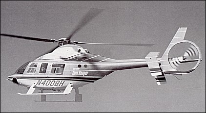
In February 1983, Bell announced the both commercial and military, single and twin-engined, Model 400 TwinRanger. This seven-seat aircraft was in the 1800-2700kg gross weight class. The Model 400 was powered by two 443shp Allison 250-C20R turboshaft engines, had a four-blade soft-in-plane main rotor, an advanced technology transmission and drive system with ‘run-dry’ capability. The aircraft entered development in 1983 with wind-tunnel testing with a one-quarter scale model and flight testing of the dynamic components on a specially modified Model 206LM LongRanger (c/n 45003, N206N) which served as test-bed and flew in March 1983. This aircraft had the four-bladed OH-58D AHIP rotor, a strengthened tail boom, a ring guard tail rotor and a deepened fuselage to increase fuel capacity. The first prototype Model 400 (c/n 48001, N3185K) flew on 30 June, 1984, powered by Allison engines. Three pre-production Model 400 TwinRangers (c/n 48002/ 48004) were built, the first of which (N3185L) flew for the first time on 4 July, 1985, the second (N3185U) in May and the third (N400BH) in June 1985. The first aircraft was later used as a ground test vehicle. It was expected that the Canadian factory, at Mirabel, Montreal, would undertake production of the Model 400 and develop the Model 400A, a variant of the Model 400 powered by a single 1000shp Pratt & Whitney Canada PW209T turboshaft engine, and employing major composites components. The programme was suspended indefinitely pending a market situation that would support an annual sales rate of about 120 aircraft. The four existing aircraft have been cancelled from the register and put in storage by Bell Helicopter Textron Canada, at Mirabel.
Model 400 Rotor diameter: 11.30m Overall length: 13.39m Length of fuselage: 11.02m Height overall: 3.56m Maximum take-off weight: 2495kg Empty weight: 1427kg Maximum speed: 278km/h Maximum cruising speed at 1525m: 244km/h Initial rate of climb: 464m/min Service ceiling: 6100m Hover ceiling outside ground effect: 3110m Hover ceiling in ground effect: 4360m Maximum range: 834km
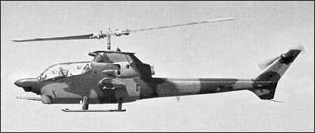
Bell announced the development of a new combat helicopter on 28 September 1971, derived from the Model 209 and 211, with company funds, with a 1.10m longer fuselage supporting a larger diameter rotor measuring 14.63m. Both the main and tail rotors had wider chord blades and the main rotor blades had double swept tips to reduce noise levels and improve performance at high speed. The nose was also modified to accept new apparatus, the available space for ammunition was increased, and the wing span was taken to 3.96m. A redesigned tail assembly was used with a lower fin for improved longitudinal stability. It also had the transmission, wide-chord two-blade main rotor and drive train of the Model 211 HueyTug. Design work was begun by a team led by Joe Tilley and construction started in January 1971. Two prototypes of the Model 309 Kingcobra were built. The first (c/n 2503, registered N309J), which flew on 10 September 1971 at Fort Worth with Gene Colvin at the controls, was offered to the Marines with Turbo Twin Pack T400-CP-400 engines, while the second prototype (which flew in January 1972) was offered to the Army with a 2890shp Lycoming T55-L7C turbine of the Model 211, derated to 2050 on take-off. The KingCobra incorporated new avionics and systems to fulfill its anti-tank mission (inertial navigation system, APN-198 radar altimeter, fire-control computer, multi-sensor sight, head-up display, helmet sighting system, FL-33 FLIR, low-light level television and, of course TOW guidance system). Armament included provision for sixteen TOW missiles under extended stub wings and a General Electric chin-turret housing a three-barelled 20mm Gatling gun with 1345 rounds. On 11 April 1972, the first prototype was damaged in an accident. To meet future Army needs it was decided to convert the twin-engined 309 into single-engined configuration. As expected, on 9 August, 1972, the Army finally cancelled the Cheyenne programme and in due course two helicopter manufacturers, Sikorsky and Bell, submitted proposals for a less sophisticated aircraft, the Model S-67 and the Model 309 respectively. Tests and demonstrations were successfully conducted with both aircraft, but the Army set up new requirements and opened a new contest within the Advanced Attack Helicopter programme (AAH) which would eventually lead to the selection of the MDD/Hughes AH-64 Apache. The Bell Model 309 (N309J) is now preserved by the US Army Aviation Museum in Fort Rucker, Alabama.
Bell 309 Kingcobra Engine: 1 x Lycoming T55-L7C turboshaft, 2155kW Main rotor diameter: 14.63m Length: 14.63m Height: 4.11m Take-off weight: 4510kg Empty weight: 2890kg Gross weight: 6350kg Max speed: 330km/h
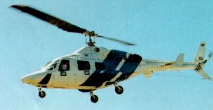
At the 1989 NBAA Convention, Bell announced its intention to develop an improved variant of its Bell 222. Powered by two 700shp Allison 250-C30-G2 turbines driving an advanced design two-blade rotor, the Model 230 could carry up to ten people in a 3.8cu.m passenger compartment. Internal fuel capacity had been increased to 930 litres with a maximum of 1359 litres with optional fuel tanks. A fixed skid undercarriage is also available and, from the 51st production aircraft, Bell will offer a variant powered by Lycoming LTS101-750 turbo-shafts. This helicopter is to be built at the company’s facility in Canada.
Two prototypes were converted from Bell 222s at the Mirabel factory near Montreal and the first of these (registered C-GEXP) accomplished its maiden flight on 12 August, 1991. The type received Transport Canada type approval on 12 March 1992 and the production aircraft (C-GAHJ) first flew on 23 May 1992. Deliveries began on 16 November 1992. A total of 37 were delivered by January 1998. The second prototype (C-GBLL) flew on 3 October 1991. An initial order for twenty was placed by Bell’s Japanese representative Mitsui & Co, in Tokyo, with first deliveries due in August 1992.
A Military demonstrator (N230CN) was leased for six months by Chilean Navy 1993-94, equipped for shipboard evaluation with Indal ASIST deck recovery system, auxiliary fuel tanks, Breeze Eastern BL 1600 rescue hoist, AlliedSignal RDR 1500B radar, Teledyne AN/APX-101 transponder, AlliedSignal KHF-950 SSB transceiver, Magnavox AN/ARC-164 UHF, Rockwell AN/ARC-186 VHF, Spectrolab SX-5 Starburst searchlight, Agema thermal imager in Heli-Dyne turret, Honeywell EDZ-705 EFIS with SPZ-7000 AFCS, Trimble TNL 7880 GPS/Omega and Flight Visions FV2000 HUD.
The first 50 aircraft were powered by two Allison 250-C30G2 turboshafts, each rated at 522kW for 5 minutes for T-O, 464kW maximum continuous, 581kW OEI for 2.5 minutes and 553kW OEI for 30 minutes. Main transmission rated at 690kW for T-O, 652.5kW maximum continuous and 548kW for single-engined operation. Usable fuel capacity 935 litres in skid gear version, 710 litres in wheeled version. Optional 182 litres of auxiliary fuel for both versions. Equipped with a two-blade main rotor with stainless steel spars and leading-edges, Nomex honeycomb trailing-edge with glass fibre skin, and glass fibre safety straps; tail rotor blades stainless steel. Aluminium alloy fuselage with integral tailboom and some honeycomb panels. The landing gear is a tubular skid type on Utility version. Executive version to have hydraulically retractable tricycle gear, single mainwheels retracting forward into sponsons; forward-retracting nosewheel fully castoring and self-centring; hydraulic disc brakes on main units. Controls are fully powered hydraulic, with elastomeric pitch change and flapping bearings; fixed tailplane with leading-edge slats and endplate fins; strakes under sponsons; single-pilot IFR system without autostabilisation. Standard layout has forward-facing seats for nine persons (2-2-2-3) including pilot(s). Options include eight-seat executive (rear six in club layout), six-seat executive (rear four in club layout with console between each pair), or 10-seat utility (2-2-3-3, all forward-facing). Customised Emergency Medical Service (EMS) versions also available, configured for pilot-only operation plus one or two pivotable stretchers and four or three medical attendants/sitting casualties respectively. Two forward-opening doors each side. Entire interior ram air ventilated and soundproofed. Dual controls optional. The main and tail rotors substantially same as Bell 222, former having Wortmann 090 blade section with 8 per cent thickness/chord ratio and swept tips. Independent (hydraulic) rotor brake. Short span sponson each side of fuselage houses mainwheel units and fuel tanks, and serves as work platform.
Bell 430 Preliminary design began in 1991 for a four-blade rotor, higher-powered and stretched variant of Bell 230, The programme was launched in February 1992 and two prototypes were modified from Bell 230 airframes: first prototype (C-GBLL; wheel-equipped) flown 25 October 1994; second prototype (C-GEXP; skid-equipped, with complete avionics suite) flown 19 December 1994. The first flight of a production 430 (C-GRND) was in 1995 and deliveries began on 25 June 1996 after Canadian type approval on 23 February. The second production aircraft, N4300 circumnavigated the world in a record time of 17 days 6 hours 14 minutes, landing back at Fairoaks, UK, on 3 September 1996. Neiman Marcus Special Edition was introduced in 2001 for Neiman Marcus store’s 75th Christmas catalogue, featuring three-colour custom metallic exterior paint scheme with NM signature. Italian leather and rosewood interior, sculpted carpets with NM logo, passenger refreshment centre, Blaupunkt AM/FM/CD entertainment centre. JetMap cabin information system with moving map displays on two ceiling-mounied monitors. Motorola cellphone and two computer ports. The first delivery, on 25 June 1996, was the sixth production aircraft (N6282X) handed over to IPTN (now Dirgantara) of Indonesia in eight-seat executive configuration. Thirteen were delivered in 1996; followed by eight, 15 and 18 in 1997-99, 11 in 2000, 14 in 2001 and seven in 2002.
430
Optimised for high cruising speed with (retractable) wheel landing gear, although traditional skids optional; inclined towards executive transport market. Bell 230 fuselage lengthened by 0.46m plug; Bell 680 all-composites four-blade bearingless, hingeless main rotor; approximately 10% power increase over Bell 230; uprated transmission; and optional EFIS. Short-span sponson each side of fuselage houses mainwheel units and fuel tanks, and serves as work platform. Fully powered hydraulic, with elastomeric pitch change and flapping bearings; fixed tailplane with leading-edge slats and endplate fins; strakes under sponsons; single-pilot IFR system without auto-stabilisation. Semi-monocoque fuselage of light alloy, with limited use of light alloy honeycomb panels. Fail-safe structure in critical areas. One-piece nosecone tilts forward and down for access to avionics and equipment bay. Short span cantilever sponson set low on each side of fuselage, serving as main landing gear housings, fuel tanks and work platforms. Section NACA 0035. Dihedral 3deg 12min. Incidence 5deg. Sweepback at quarter-chord 3deg 30min. Fixed vertical fin in sweptback upper and lower sections. Tailplane, with slotted leading-edge and endplate fins, mounted midway along rear fuselage. Small skid below ventral fin for protection in tail-down landing. Four-blade main rotor with stainless steel spars and leading-edges. Nomex honeycomb trailing-edge with glass fibre skin, and glass fibre safety straps; tail rotor blades stainless steel. Rotors shaft-driven through gearbox with rwo spiral bevel reductions and one planetary reduction. Main blade and hub life, 10.000 hours. Tubular skid type on Utility version. Executive version has hydraulically retractable tricycle gear, single mainwheels retracting forward into sponsons; forward-retracting nosewheel fully castoring and self-centring; hydraulic disc brakes on main units. Mainwheel tyre size 18×5.5, nosewheel 5.00-5. Emergency floats optional. Two Rolls-Royce 250-C40B turboshafts, each rated at 603kW for T-O and 518kW maximum continuous. OEI ratings 701kW for 30 seconds, 656kW for 2 minutes, 623kW for 30 minutes and 602kW continuous. Chandler Evans FADEC. Transmission rating 779kW for 5 minutes for T-O, 737kW maximum continuous. Power train TBO, 5,000 hours. Usable fuel capacity 935 litres in skid version, 710 litres in wheeled version; provision in both versions for 182 litre auxiliary tank. Fuel system is rupture resistant, with self-sealing breakaway fittings. Standard layout has forward-facing seats for nine persons (two-two-two-three) including pilot. Options include 10-seat layout (two-two-three-three); eight-scat executive (rear six in club layout), six-seat executive (rear four in club layout with console between each pair); and five- and four-seat executive with one or two refreshment cabinets; seat pitches vary between 86cm and 91cm. Pilots on crashworthy (energy attenuating) seats, which are optional for passengers. Customised emergency medical service (EMS) versions also available, configured for pilot-only operation plus one or two pivotable stretchers and four or three medical attendants/sitting casualties respectively. Two forward-opening doors each side; EMS version has optional stretcher door between forward and rear doors on port side. Entire interior ram air ventilated and soundproofed. Dual controls optional. Standard equipment includes rotor and cargo tiedowns, ground handling wheels for skid version, retractable 450W search/landing light. Options include dual controls, auxiliary fuel tankage, force/feel trim system, more comprehensive nav/com avionics, 272kg capacity rescue hoist, 1587kg capacity cargo hook, emergency flotation gear, heated windscreen, particle separator and snow baffles. The programme cost US$18 million, 35% financed by Canadian Defence Industry Productivity Program (DIPP) and repayable as royalty on each sale.
Bell 230 Engine: 2 x Allison 250-C30G/2, 720 shp each, dual max: 690 kW. Instant pwr: 520 kW. Rotor dia: 13.8 m. Empty wt: 2270 kg. MTOW: 3813 kg. Payload: 1472 kg. Useful load: 1270 kg. Max speed: 140 kts. Vne: 150 kts. Max cruise: 135 kts. Max range: 705 km. HIGE (@MAUW): 12,400 ft. HOGE (@MAUW): 7300 ft. Service ceiling: 14,100 ft. Opt fuel cap: 1359 lt Crew: 1/2. Seats: 8/10. Rescue hoist capacity: 136kg Cargo hook capacity: 1,270kg
Bell 430 Engine: Allison 250-C40. Instant pwr: 582 kW. Rotor dia: 13.8 m. MTOW: 5443 kg. Max cruise: 135 kts. Vne: 150 kts. Max range: 705 km. Seats: 8/10.
In March 1974 Bell decided to commit its own resources to the development of a new twin-turbine, ten-seat helicopter. This helicopter was evolved from studies begun in the late 1960s which had led, in 1973, to the Design D-306, a twin-turboshaft helicopter. The engines were to be either the 500shp Allison 250-C28, the 590shp Lycoming LTS-101 or the 650shp Pratt & Whitney Canada PT7B driving the Bell classic two-blade main rotor. The D-306 could accommodate two pilots and eight passengers (four passengers in executive configuration). In January 1974, a full-scale mock-up of the D-306 was displayed at the Helicopter Association of America (HAA) convention in order to study the market potential and to gather the would-be customers remarks in order to upgrade the project. The reactions were so promising that, on 20 April, 1974, Bell announced its decision to go ahead with the Model 222, five prototypes of which were to be built and which were quite similar to the D-306 (the windscreen was improved and the fuselage lengthened by a few inches). The Model 222 was the first completely new Bell design to reach production status since the JetRanger and the Model 222 was described then as ‘the first American made light twin-turbine helicopter’. It had a semi-monocoque light alloy fuselage with a hydraulically retractable tricycle undercarriage. The two Avco Lycoming turboshafts drove a two-blade main rotor through a gearbox with two spiral bevel reductions and one planetary reduction. The maiden flight of the prototype was expected by the end of 1975 but, in fact, the first prototype (c/n 47001, N9988K) got into the air on Friday 13 August, 1976, with Donald Bloom at the controls. Certification by the FAA under FAR Part 29 was received on 16 August, 1979, followed by approval for VFR operation on 20 December of the same year. On 15 May, 1980, the Model 222 received FAA approval for single-pilot IFR operation. The Bell 222 has a light alloy structure, and a fuselage built around a large cabin which can seat two pilots and five or six passengers in the executive trim. In all configurations, there is a bench seat at the back for three, which fits into the L-shape of the fuel tank behind it. The executive Bell 222 is sold with full IFR capability. One alternative is the offshore configuration for ferrying eight passengers to offshore oil platforms. The large main rotor with two wide blades is of steel with a honeycomb core. The blades are held to the rotor hub by standard Bell elastomeric bearings. The tail rotor is also metal with two blades. The twin Lycoming LTS-101-650 engines are mounted side-by-side above the fuselage and have integral particle separators. The fuel is contained in three tanks, one in the fuselage and two in the sponsons into which the main landing gear members retract. During flight tests several improvements were introduced on the prototypes, the most obvious being a completely new tail configuration. With the fourth prototype (c/n 47004, N680L) a new tail layout was adopted: the T tail was replaced by tailplanes and end-plate fins fixed forward of the rear fuselage. The main rotor diameter has been increased by 12 in (30,5 cm) and a slightly more powerful version of the Lycoming turboshaft engine has been adopted, to off-set some weight growth attributable to the new tailplane and larger rotor. The fifth prototype (c/n 47005, N2228X), representative of the production aircraft, was presented at the Paris Air Show in June 1978. In fourteen months, the five prototypes logged more than 600 flying hours and by December, 1977, the figure of 700 hours was reached. The first for Petroleum Helicopters were delivered in January 1980.
Bell 222 ZK-HFQ
Production was launched with a backlog of orders for some 140 aircraft and Bell had to boost its planned production from 125 machines the first year to 137. On 16 January 1980, Petroleum Helicopters Inc (New Orleans) received the first of its sixteen machines soon followed by Schiavone Construction which received an aircraft in executive configuration. Heliflight Systems (Houston), Aerogulf Sales Co (Dubai), Bemor Agencies (Bermudas), CSE Aviation Ltd (UK) and Astra Helicopters (South Africa) were among the main customers. On 18 January 1981, Bell Helicopters delivered its 25,000th helicopter, a Model 222, to Omniflight Helicopters. The Model 222 and 222A, first production variants were powered by two 592shp Avco-Lycoming LTS 101-650C-3 engines, their dry weight of only 110kg each providing a maximum power/ weight ratio of 4.58kW/kg at maximum rating. The Model 222B was the second main production variant with accommodation for seven to nine passengers. The Model 222B incorporates numerous improvements such as a taller main rotor mast, increased diameter narrow-chord blades, larger tail rotor and lengthened tail boom. The powerplant consists of two 684shp Textron Lycoming LTS 101-750C-1 turboshafts. The fuel is contained in five crash resistant tanks located in the fuselage as well as in the sponsons, with a total capacity of 710 litres. The Model 222B Executive is the luxury variant for five or six people with complete systems and avionics such as IFR, Sperry coupled automatic flight control system and VOR/LOC. Luxury equipment includes automatic temperature control, fluorescent and reading lights and window curtains. A stereo system and refreshment cabinet are optional. In 1982, the Model 222B became the first transport category helicopter to be certificated by the FAA for single-pilot IFR flight without stability augmentation. Model 222U and 222UT: the Model 222UT (UT for Utility Twin) variant is externally recognisible by its tubular skid undercarriage in place of the usual retractable wheels. It can accommodate up to eight passengers and could have a fuselage mounted flotation system. The powerplant is the same as for the Model 222B but fuel capacity has been increased to 930 litres. This variant received VFR and single-pilot IFR certification during the spring of 1983. The basic Model 222B feature include: ROTOR SYSTEM: Two-blade main rotor. Blade section Wortmann 090. Thickness chord ratio 8 per cent. Each blade has a stainless steel spar with bonded glass fibre safety straps to retard crack propagation and offer secondary load path; replaceable stainless steel leading-edge; and afterbody of Nomex honeycomb covered with glass fibre skin. Each blade is attached to the rotor head by two chordwise bolts. Small trim tab on each blade. Completely dry titanium main rotor hub has conical elastomeric bearings. Two-blade tail rotor of stainless steel construction, with preconing, underslung feathering axis and skewed flapping axis. Rotor blades do not fold. A rotor brake is standard. ROTOR DRIVE: Rotors shaft driven through gearbox with two spiral bevel reductions and one planetary reduction. Transmission rating (two engines) 690kW. Single-engine rating 548kW. Main rotor engine rpm ratio 1:27.4; tail rotor engine rpm ratio 1:5.08. SPONSONS: Short-span cantilever sponson set low on each side of fuselage, serving as main landing gear housings, fuel tanks and work platforms. Section NACA 0035. Dihedral 3deg 12min. Incidence 5deg. Sweepback at quarter-chord 3deg 30min. All-metal structure of light-alloy sheet and honeycomb. No movable surfaces. FUSELAGE: Semi-monocoque structure of light alloy, with limited use of light-alloy honeycomb panels. Fail-safe structure in critical areas. One-piece nosecone tilts forward and down for access to avionics and equipment bay. TAIL UNIT: Cantilever structure of light alloy. Fixed vertical fin in sweptback upper and lower sections. Tailplane, with slotted leading-edge and endplate fins, mounted midway along rear fuselage. Small skid below ventral fin for protection in tail-down landing. LANDING GEAR: Hydraulically retractable tricycle type. All units retract forward, mainwheels into sponsons. Free-fall extension in emergency. Oleo-pneumatic shock-absorbers, with scissored yoke. Self-centring nosewheel, swivelling through 360degrees. Single wheel and tyre on each unit. Mainwheel tyres size 6.00-6, pressure 5.18 bars. Nosewheel tyre size 5.00-5, pressure 4.14 bars. Hydraulic disc brakes. New-type water-activated emergency pop-out floats optional. Model 222UT has skid-type landing gear and lock-on ground handling wheels, with fuselage-mounted flotation system optional. POWER PLANT: Two Textron Lycoming LTS 101-750C-1 turboshafts, each rated at 510kW for take-off, mounted in a streamline housing above the cabin and aft of the rotor pylon. Bell focused pylon with nodalisation. Fuel contained in five crash-resistant internal bladders, in fuselage and sponsons, with total capacity of 710 litres in Model 222B. Model 222UT has maximum fuel capacity of 931 litres. Rear seat fuel tank, capacity 246 litres, and parcel shelf fuel tank, capacity 181 litres, optional on both models. Single-point refuelling on starboard side of fuselage. Oil capacity 6.5 litres per engine. ACCOMMODATION: Pilot and seven passengers in standard 2-3-3 layout, alternatively pilot, co-pilot and six passengers. Two additional passengers can be accommodated in a high-density 2-2-3-3 arrangement. Energy attenuating seats, all with shoulder harness in Model 222B. Crew door at forward end of cabin on each side; cabin door on each side immediately forward of wing. Space for 1.05cu.m of baggage aft of cabin, with external door on starboard side. Ventilation standard; air conditioning and heating optional. First deliveries of the Model 222UT were in September 1983. Among the main operators are the New York City Police Department, the Port Authority of New York, Michigan State Police, West Virginia State Police and Lloyd Helicopters. From 1982, the fourth prototype (N680L) served as test bed for the Model 680 four-blade composite bearingless rotor system, designed to improve performance and reduce noise. On 10 November, 1987, this Model 222 flew with a digital control system developed by Bell and Lucas Aerospace which gave the engine the ability to adapt its characteristics in flight. To 1992, one hundred and fifty-six Model 222Bs and seventy-two 222UTs have been delivered, mainly on the civil market. Only two aircraft are known to have been taken on charge by military customers: one by the Uruguayan Air Force and the other by the Uruguayan Navy. Production ceased in 1989.
Versions:
222A Initial production model powered by twin 462kW Lycoming LTS 101 650C-3 turboshaft engines. Replaced from late 1982 by the Model 222B. Total 82 built.
222B Standard production model from late 1982. More powerful, 510kW Lycoming LTS 101 750C-1 engines; fuselage increased by 0.43m and main rotor diameter 0.69m larger. Strakes added to sponsons. First flight 1 August 1981; FAA certification 30 June 1982. On 29 July 1982, the 222B became the first transport category helicopter to be certified by the FAA for single-pilot IFR flight without stability augmentation. Total of 26 produced between 1982 and 1987.
222B Executive Fully equipped for both single- and dual-pilot IFR flight. Honeywell coupled automatic flight control system to provide stability augmentation and automatic hold for attitude, altitude, heading and airspeed, plus VOR/LOC course and glide slope hold during approach. Collins Pro Line avionics include dual VHF com, dual VOR nav with glide slope. ADF, marker beacon receiver, transponder, DME and area navigation. Luxury accommodation for five or six passengers, with automatic temperature control, fluorescent and reading lights, window curtains and ceiling speakers. Optional stereo system and refreshment cabinet.
222UT (Utility Twin) Utility version, incorporating the improvements and power plant detailed for the Model 222B. Retractable tricycle landing gear replaced by tubular skid gear with lock-on ground handling wheels. Fuselage-mounted flotation system optional. Standard seating for a pilot and six or seven passengers. Optional layout for a pilot and eight passengers. First flight 7 September 1982. VFR and single-pilot IFR certification received in Spring 1983; customer deliveries began in September 1983. Total of 80 built up to 1989.
Specifications:
Bell 222 Power Plant: Two Lycoming LTS 101-650C2 turboshafts each with a contingency rating of 675 shp, take-off rating of 615 shp and continuous rating of 590 shp. TBO: 2400 hr Max continuous speed, 173 mph (278 km/h) at sea level Normal cruise @ 3000 ft: 135 kts. Long-range cruising speed, 150 mph (241 km/h) at sea level Hovering ceiling (OGE), 8,200 ft (2500 m) in ISA and 4,000 ft (1 220 m) in ISA plus 20 deg C Hovering ceiling (IGE), 13,000 ft (3962 m) in ISA and 10,000 ft (3050 m) in ISA plus 20 deg C Single-engine ceiling, 9,000 ft (2743 m) in ISA and 5,100 ft (1555 m) in ISA plus 20 deg C Range with 20-mm reserve, 400 mls (644 km) at 8,000 ft (2440 m) Max rate of climb: 1580 fpm. Service ceiling: 12,800 ft. FAA empty weight, 4,250 lb (1930 kg) Standard empty weight: 4860 lb Useful load, 2,950 lb (1 340 kg) Take-off gross weight, 7,200 lb (3270 kg) Fuel flow @ normal cruise: 482 pph. Endurance @ normal cruise: 2.5 hr. Max ramp weight: 7850 lb Max useful load: 2990 lbs. Max landing weight: 7850 lbs. Max sling load: 2100 lbs. Disc loading: 6.3 lbs/sq.ft. Power loading: 6.4 lbs/hp. Max usable fuel: 1287 lbs. Main rotor diameter, 40 ft 0 in (12,19 m) Overall length, 47 ft 9 in (14,55 m) Overall height, 11 ft l .5 in (3,39 m) Fuselage length: 10.98m Undercarriage ¬track, 9ft (2,74 m) Wheelbase, 11 ft 9 12 in (3,59 in) Span over sponsons, 14 ft (4,27 m). Accommodation: Up to 10 including pilot. Baggage capacity, 43 cu ft (1,22 cu.m) in aft cabin and fuselage baggage compartment.
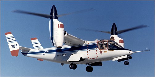
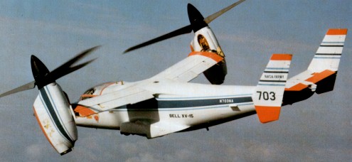
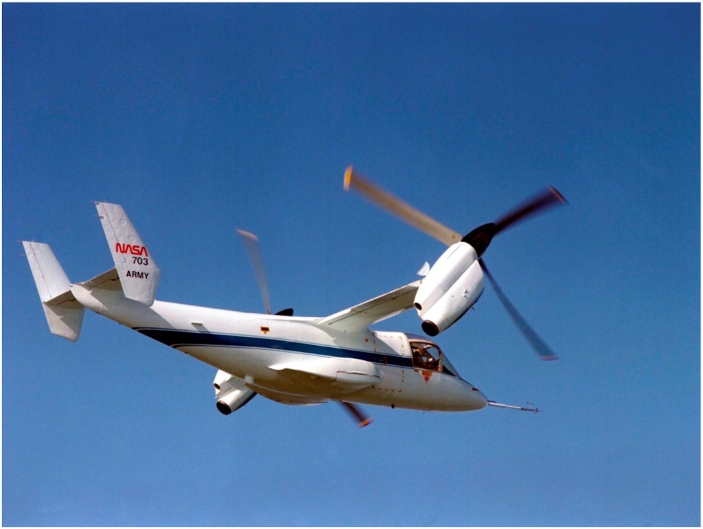
In 1965, the U.S. Army issued a Request for Proposal for what it called the Composite Aircraft Program. Composite, in this case, was for a vehicle that would have both helicopter and airplane characteristics, specifically, looking for a single aircraft to replace both the CH-47 helicopter and the C-7 “Caribou”. Three contractors were selected to perform design studies in 1966 and Lockheed and Bell were chosen to perform further exploratory definition studies, which were completed in September 1967. However, the Army dropped the development due to limited funds. Bell decided in 1968 to continue development for a proposed civil tilt-rotor aircraft, designated the Model 300. Initial work led to the design for a 4285kg aircraft powered by two Pratt & Whitney PT-6 engines powering 7.6m diameter rotors. One-fifth scale aerodynamic and aeroelastic models were built and tested extensively from 1969 through 1973. Full size rotor and rotating mechanisms were whirl tested to determine their hover performance and then tested in 1970 at the NASA Ames 12m x 24m wind tunnel at various rotation speeds, angles, and airspeeds up to the maximum tunnel speed of 370km/h. The rotor met or exceeded all performance and stability predictions. Then, in 1972, NASA and the U.S.Army Air Mobility Research and Development Laboratory jointly started the Tiltrotor Research Aircraft Program. Since the Tiltrotor Research Aircraft Program was to be strictly a research program and would not lead to the production of an operational aircraft, costs were to be kept under control by not making weight minimization a major factor and encouraging the use of off the shelf components. Advanced technologies like fly-by-wire and composite structures were to be avoided. Weight growth and performance shortfalls would be tolerated in order to minimize cost and schedule impacts. Even the number of aircraft to be built was a factor. The two aircraft option was selected because of the high accident rate experienced by most other VTOL research programs. Bell’s proposal started with the Model 300’s design and evolved it into Model 301. Bell kept the rotor and transmission, but replaced the engines with the more powerful Lycoming T-53 because of the requirement to hover with only one engine and the greater empty weight and useful loads required. Another benefit of the engine switch was that the T-53 already had an oil system that could operate with the engine pointed vertically, which had been developed for the CL-84 program. Bell’s proposal was submitted on January 22, 1973, and comprised 300 volumes weighing 350kg. Bell’s proposal was selected in April 1973. NASA awarded contract NAS2-7800 for $28 million for the final design, fabrication, and preliminary testing of two XV-15s on July 31. The total estimated cost of the six-year program was $45 million. The 12.8m long fuselage design was of a conventional aircraft, semi-monocoque, , and using light alloy material. There was no fuselage pressurization, and the structure was stressed from +3 to -0.5 G. The airframes were designed for minimum service lives of 1000 flight hours over five years. The tricycle landing gear came from the Canadair CL-84. It utilized Goodyear magnesium main and nose wheels, and Goodyear hydraulically operated magnesium/steel disc brakes. The full-swiveling nose wheel incorporated shimmy dampers and a centering device. It retracted into a bay forward of the cockpit. The main wheels retracted into external pods on each side of the fuselage. A switch on the main gear strut prevented inadvertent gear retraction and tilting of the pylons more than 30 degrees from vertical when the aircraft was on the ground. The landing gear was structurally designed to withstand a touchdown sink rate of 3m per second at full gross weight. A 14500kg/sq.m nitrogen gas system provided for emergency extension in the event of a hydraulic failure. The H-tail consists of a horizontal stabilizer with a vertical stabilizer on each tip. This configuration was selected to provide improved directional stability at and near zero yaw angles. Rockwell International’s Tulsa Division built the fuselage and tail units under subcontract. Two pilots sat side-by-side in Rockwell-Columbus LW-3B ejection seats, entering through a door on the right side of the cargo compartment. The flight deck was heated, ventilated, and air conditioned, but not the cargo compartment. The cabin could accommodate nine personnel if not filled with test equipment. The wing measures 9.75m across, has a constant chord measuring 1.6m, and a area of 15.7sq.m (one of the design requirements was that the XV-15 be able to fit in NASA Ames’ 12m x 24m wind tunnel, which influenced the wingspan and rotor size). It is swept forward 6.5 degrees, not for any futuristic aerodynamic reasons, but to insure there would be adequate clearance when the rotor blades flex in airplane mode. Wing dihedral is 2 degrees. Along the trailing edge, a flap measuring 1sq.m occupies the inboard third, and a flaperon measuring 1.85sq.m occupies the outer two thirds. The flaps can be deflected down to 75 degrees to help provide additional lift at low speeds. In hover, the flaps and flaperons deflect downward to reduce slipstream interference by the wing. The problems with the wing/rotor/pylon stability that plagued the XV-3 were eliminated by designing a very stiff wing and nacelle/wing attachment, and by placing the rotor hub as close to the wing as possible. Each wing holds two fuel bladders that form a single crashworthy fuel tank in each wing. Together they hold a total of 830 litres. The pump in each wing tank is powered from a different electrical system. In the event of a pump failure, both engines can feed from the same tank, or in the case of an engine failure, one engine can feed from both tanks. Cross feeds activate automatically in the event of a pump failure to assure uninterrupted fuel flow to both engines. In the event of a complete loss of electrical power to both pumps, the engine driven pumps still can maintain adequate fuel flow. An Avco Lycoming LTC1K-4K engine, a modified version of the standard T53-L-13B engine, is mounted at each wing tip. They are rated at 1250shp for continuous operation, 1401shp for 30 minutes, 1550shp for 10 minutes for take-off, and 1802shp for two minutes for emergency power. Power is transmitted from the engines to the rotors using a coupling gearbox and transmission, which reduce the engine speed of approximately 20000 revolutions per minute down to a rotor speed of about 565 revolutions per minute in hover. The three-bladed, semi-rigid rotors measure 7.6m in diameter and have a 36cm chord. They were made of stainless steel and have a large amount of twist. (In July 1979, Bell received a contract from Ames for preliminary design of a composite rotor blade that would offer improved performance and increased life expectancy, compared to the existing metal blades. A set eventually was tested, but did not work well.) There are no flapping hinges, but the rotors can flap forward or aft as much as 6 degrees. To assure power to both rotors in the event of an engine failure, a shaft that runs through the wing interconnects the two transmissions. As a result of the interconnect, both rotors turn when the first engine starts. In the event of a double engine failure, both rotors will autorotate at the same speed. The nacelle tilt can be varied from horizontal to 5 degrees aft of vertical. Interconnected double ballscrew actuators operate the tilt mechanism in each nacelle. This assures that both nacelles always will be at the same position. The interconnected drive shafts and redundant tilting mechanisms permit single engine operation and fail-operate tilt capability. The cockpit has dual controls and resembles a helicopter cockpit, including a collective stick. The flight controls are designed to permit single pilot operation from either seat. In airplane mode, the control columns and rudder pedals work conventionally. In hover mode, the stick functions as a cyclic pitch controller. The mechanical mixing unit does everything needed to convert the controls from the helicopter mode to the fixed wing mode. Control authority between helicopter and airplane mode is phased in as a function of the nacelle tilt angle. This includes changing the rotors from cyclic pitch control in vertical flight to constant speed control for fixed wing flight. In airplane mode, the collective lever can still be used as a power lever. Moving the collective lever causes the throttles on the center console to move. Two switches, mounted on the collective lever and operated by the pilot’s thumb, control the nacelle tilt angle. One pivots the nacelles from end to end in about 12 seconds and allows them to be stopped at any position. The other switch moves the nacelles between pre-selected angles of 0, 60, 75, and 90 degrees (relative to horizontal). To rotate the nacelles, electrical valves activate hydraulic motors. In the event of a complete electrical system failure, the pilot can manually open the valves using T-handles in the cockpit. This will drive the nacelles to the helicopter position. Sperry Rand built the original navigation/guidance system. A digital computer provides navigation and control information to the pilot using advanced mechanical and electronic displays. The Calspan Corporation of Buffalo NY designed the Stabilization Control Augmentation System to improve its flight characteristics. The XV-15 does not incorporate fly-by-wire. Ailerons, elevator, and rudder are hydraulically boosted with a triple hydraulic system. They remain active in all flight modes.
The XV-15’s empty weight is 4315kg with a vertical take off weight of 5865kg. This allows 495kg for instrumentation, 180kg for pilots, and 630kg of fuel, while leaving a few left over for growth. Original estimated performance included a maximum level speed of 610km/h, service ceiling of 8845m, and a range of 800km. None of these goals ever were achieved, but the XV-15 did achieve its primary objective of proving the practicality of the tilt rotor concept.
In April 1974, Rockwell International (Tulsa Division) received a contract for the construction of the fuselage and the tail assembly of the two XV-15 airframes. On 2 October, 1975, components of the first prototype were delivered to Bell Helicopter in Fort Worth where final assembly would be undertaken. Aircraft No.1 (c/n 00001, N702NA) was rolled out, at Arlington, on 22 October, 1976. Before tiedown dynamic tests simulating all flight modes, the XV-15 No.1 underwent an extensive integration checkout. Ground runs began in January 1977, and included 100 hours of system qualification tests on an elevated test stand in both the helicopter and airplane modes to demonstrate that the aircraft met final flight qualification requirements. The first hovering flight was performed on May 3, 1977, followed by hover and low speed evaluations. This short test effort consisted of only three hours of hovering during May. No problems that warranted corrections were uncovered. Following these flight tests, the transmissions and rotors were torn down, inspected and reassembled. Because of NASA’s insistence on full-scale wind tunnel tests before attempting a conversion, aircraft #1 was shipped by C-5A to NASA’s Ames Research Center in March 1978 for wind tunnel tests. These tests were conducted in the Ames 12m x 24m foot wind tunnel in May and June 1978. Twenty hours of tunnel tests were performed at airspeeds between 110 and 330km/h. Configurations consisted of the rotors in helicopter and airplane positions, and numerous intermediate positions that would be encountered during transition. No unusual characteristics were noted in any of the tests conducted. Following the wind tunnel tests, the #1 aircraft was torn down and refurbished at NASA Ames.
The second XV-15, #N703NA, was nearing completion. Since the program lacked funds to keep two aircraft on flight status, testing resumed with the #2 aircraft, beginning ground tests in August 1978 at Arlington. Numerous minor problems plagued the aircraft during these tests, including a stress corrosion crack in the left engine gearbox, a clutch misengagement, and foreign object damage within the transmission. It made its first hovering flight on April 23, 1979, with Ron Erhart and Dorman Cannon, Bell’s XV-15 project pilot, at the controls. Conversion tests soon began, starting by rotating the nacelles 5 degrees forward on 5 May 1979. Successive tests gradually rotated the nacelles closer to horizontal, until the first complete conversion was made on July 24, 1979. The XV-15 also achieved a forward speed of 295km/h on this 40 minute flight. On 21 April, 1980, No.2 prototype reached 485km/h at 2530m. In one year of testing, aircraft No.2 logged 40 hours flying.
The Navy became interested in the XV-15 and because of continuous funding shortfalls, the Naval Air Systems Command began providing funding in 1979 and 1980 to insure the XV-15 flight testing would proceed up through the completion of envelope expansion flights. In exchange, the Navy would be allowed to perform flight evaluations.
During the contractor test program, all potential failures were simulated in actual flight or on the ground. On December 5, 1979. an actual engine failure occurred when the turbine seized. The transmission interconnect system worked properly, and both rotors continued to turn as designed. The predicted speed of 555km/h true airspeed was demonstrated with maximum rated power at a 4880m density altitude in June 1980. The contractor flight test phase was completed in August 1980. The basic conversion corridor and airspeed/altitude envelope up to 16,000 feet was demonstrated. About 100 full conversions were made. Some resonance problems were uncovered, as is normal in any helicopter development, but they were fixed quickly. Upon completion of the contractor flights, XV-15 #2 was shipped to NASA’s Dryden Flight Research Center for continued testing, where it was joined by aircraft #1. Both XV-15s then operated at Dryden for a short period. XV-15 #1 returned to Bell in September 1981. Flight testing by both NASA and Bell continued into the 1980s, and the two XV-15s proved to be virtually free of any significant problems. Additional accomplishments that were demonstrated included:
1.7 hour cruise endurance in airplane mode.
Cruise speed of 425km/h.
Take off as helicopter, fly twice as fast as a helicopter, and deliver payloads on half the amount of fuel when traveling distances of greater than 185km.
Autorotation descents in helicopter mode, but never to a full touchdown.
STOL take-offs with the nacelles tilted between 60 and 70 degrees, at the maximum gross weight of 6765kg. For taxiing on wheels, it was found that tilting the nacelles forward of vertical only 1 degree was enough to start the XV-15 moving forward. Tilting the nacelles aft of vertical brings the aircraft to a quick stop. The XV-15 tends to rock a bit more than other aircraft because of the weight of the engines and props all the way out at the wing tips. In hover, roll control is provided by differential rotor collective pitch, pitch control by cyclic pitch, and yaw by differential cyclic pitch. For maneuvering in the hover mode, many of the maneuvers normally performed by moving the cyclic control are done by tilting the nacelles. A combination of rotor angle and cyclic pitch also is used to vary the pitch attitude without moving forward. By tilting the rotors forward and simultaneously putting in aft cyclic control, the nose will pitch down, giving improved visibility over the nose. Vertical liftoff is very easy, as the XV-15 holds attitude on liftoff. Lateral movement is accomplished by banking slightly so that the thrust has a small side component. The XV-15 can travel sideways at 65km/h with no tendency to turn into the wind. It can hover backwards up to 65km/h. Touchdown surfaces can have an uphill or downhill slant of up to 15 degrees. Single engine performance is relatively poor, with single engine hover possible under only a very few conditions. During conversion from hover to conventional flight, there is a tendency to lose lift and sink, requiring the pilot to add power, but this is normal on all VTOL aircraft. With the nose up and full aft stick, level stalls in the clean configuration give a slight vibration at 205km/h. The aircraft will begin to sink, but there is no wing drop or other bad effects. In helicopter autorotation mode, the best descent rate of 11m/s is achieved at 140km/h. At 165km/h, the descent rate increases to 20m/s. For final approaches, pilots use nacelle tilt angle instead of pitch inputs to control airspeed. The 630kg of fuel contained in the wings proved to allow for only about a 280km range. An auxiliary tank holding an additional 405kg eventually was added to the fuselage, which increased the range to about 520km. In March 1982, aircraft #1 made a demonstration tour of East Coast facilities, which included seven flight demonstrations at six different locations in eight days. One flight included a stop at the helipad at the Pentagon. While on the tour, the XV-15 flew 4815km and needed only routine daily preflight maintenance. Following this East Coast tour, #1 was modified at Bell’s Arlington facility to perform an electronics mission evaluation. Items added included an APR-39 radar warning system and chaff dispenser system. The aircraft departed for NAS China Lake in California in May, then on to Ft. Huachuca in Arizona in June, and finally on to San Diego for sea trials. Shipboard evaluations were performed aboard the amphibious assault ship USS “Tripoli” off the San Diego coast in July 1982. Fifty-four vertical landings and take-offs (of which five were STOL take-offs) were performed. Other mission related evaluations included over-water rescue and simulated cargo lifting, which were demonstrated in May 1983, and simulated air-to-air refueling, which was performed in September 1984. By 1986, both aircraft had accumulated a total of 530 flight hours, made 1500 transitions, and reached an altitude of 6860m (while still maintaining an 4m/s climb capability). In March 1990, #1 set numerous time to climb and sustained altitude records for this class of aircraft. These included a climb to 3000m in 4.4 minutes and to 6000m in 8.46 minutes, without even performing extensive climb tests to develop an optimal climb profile. It also sustained an altitude of 6860m with a dummy payload of 990kg in addition to more than 450kg of test instrumentation. Under the new JVX programme Joint Services Advanced Vertical Lift Aircraft Program) the XV-15 served as test-bed. In direct relation to the JVX programme, XV-15 No.1 was tested in Fort Huachuca to evaluate its ability to accomplish SEMA missions (Special Electronics Mission Aircraft); the aircraft was sent to China Lake to measure its radar signature and, on 2-5 August, 1982, off San Diego, Lieut-Cdr John Ball and Dorman Cannon conducted the initial shipboard evaluation on board the amphibious assault ship USS Tripoli (LPH-10). This evaluation included vertical and short rolling take-offs, hovering flights and vertical landings. On this occasion, one of the 54 XV-15 landings was the ship’s 60.000th. The aircraft was then sent back to Fort Worth to undergo a complete overhaul and to receive several modifications. By the end of August 1982, the two prototypes had logged 289 hours of flight testing. The two XV-15s were then used in a research programme to explore the limits of the operational flight envelope and assess its application to military and civil transport needs. Late in 1987, the XV-15, piloted by Dorman Cannon and Don Borge, demonstrated its capabilities in the civil transport role at Washington and Chicago. The Chicago demonstration was conducted from Miegs Field in the very heart of the city. As of June 1990, XV-15 #1 was based at Bell Helicopter’s Flight Research Center in Arlington, TX, for continuing engineering development. XV-15 #2 was based at Ames for continuing tilt-rotor research. The two aircraft had accumulated 825 hours. By 1990 the XV-15 was flown by over 185 pilots with widely varying experience and capability levels, including several low-time private pilots. Numerous admirals, generals, and at least one U.S. senator and one service secretary flew as guest pilots. Each flight consisted of a brief demonstration of helicopter, conversion, and airplane modes by a Bell test pilot. The guest pilot then took over the controls. After a few minutes of familiarization, he was talked through an airplane stall, single engine operation, and conversion/ reconversion at altitude. They then return to the airport for several take-offs and landings, usually converting to airplane mode and back to helicopter mode each trip around the pattern. Guest pilots rated the XV-15 as easy or easier than a helicopter to hover. Conversion was unanimously said to be straightforward, and with a low workload. Handling qualities in airplane mode were excellent. Most also noted the low interior noise and smooth ride. FAA test pilots also flew the XV-15 in order to evaluate its potential for certification of a civil tilt rotor aircraft. While they saw no technical reasons for not being effective in the civil role, they determined that a review of Part 25, which sets standards for large transport aircraft, and Part 29, which sets standards for helicopters, would be needed in order to establish appropriate certification criteria. XV-15 #1 remained in service at Bell’s flight research center, where it was used as a concept demonstrator and marketing tool for the V-22 Osprey that was by then being developed. It was flown regularly until August 1992, when it was damaged beyond economical repair. A mechanical failure in the control system caused the aircraft to roll over while it was hovering. The crew was not injured, but the wing and one nacelle sustained extensive damage. At the time of the incident, #1 had flown nearly 841 hours. The forward fuselage was salvaged and put to use as a simulator to help develop Bell’s upcoming civil tilt rotor aircraft. XV-15 #2 remained at Ames through the 1980s. In 1986, it was fitted with composite rotor blades built by Boeing Helicopter. Sporadic testing was accomplished through 1991, when it was stopped due to a problem with the blade cuff that resulted in an emergency landing. While the blade cuff was being re-designed, NASA decided to put the airframe down for a major airframe inspection that would be due soon, anyway. Program funds again ran out before the inspection could be completed. #2 would remain partially disassembled until mid 1994. It had accumulated just over 281 hours. With Bell anxious to resume tilt rotor development, they established a Memorandum of Agreement with NASA and the Army in 1994 which transferred XV-15 #2 to Bell and allowed them to return it to service at no cost to the government. The disassembled aircraft was shipped to Arlington, Texas, and the refurbishment and inspection began in mid 1994. The original metal rotor blades were put back on, and the aircraft resumed flight testing in March 1995. Much of Bell’s recent research has focused on reducing noise in order to make civil tilt rotor more acceptable for operating in crowded urban areas. Tests were being conducted to determine the major sources of noise. As of the end of 1998, the remaining XV-15 had accumulated a total of 530 flight hours and remained in service at Bell’s Arlington facility to continue developing and refining Tilt Rotor technologies.