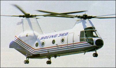
First flown on 10 June 1987, the Model 360 is a privately developed advanced technology rotorcraft, designed to research the company’s other rotorcraft programs. The helicopter features advanced aerodynamics and extensive use of composite materials including the fuselage, rotor shafts, blades and hubs. Powered by twin Avco-Lycoming AL5512 engines (4200shp) the Model 360 has a 370km/h cruise speed. The aircraft’s advanced cockpit features cathode ray tube displays, multi-function callouts, digital automatic flight control system and other improvements to reduce pilot workload. Only one model 360 was built (N360BV).
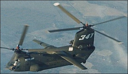
First flown on May 27, 1970, the Boeing Vertol 347 was a CH-47A modified for research with wings, four-blade rotors, retractable u/c, and fly-by-wire controls. The aft was pylon taller. The CH-47A was Boeing c/n 164 / US Army Serial number 65-7992.
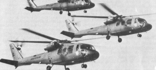
In 1971 the US Department of Defense issued a requirement for a new UTTAS (Utility Tactical Transport Aircraft System) helicopter to replace the Bell UH-1 in service with the US Army. The specification called for an aircraft capable of lifting an entire eleven-man infantry squad, or an equivalent weight in cargo, to medium altitudes at a minimum cruising speed of 323kph, and at considerably higher ambient temperatures. All designs proposed in response to the specification were required to use two General Electric T700-GE-700 turboshaft engines, and were to have wheeled landing gear, duplicate or heavily armored critical mechanical components, manual rotor blade folding, and only minimal avionics. In August 1972 the two leading contenders for UTTAS hardware were Sikorsky, with its S-70 ordered for evaluation as the YUH-60A, and Boeing Vertol, with the Boeing Vertol Model 179 (YUH-61A).
Boeing Vertol 179
The Model 179 was the first Boeing Vertol design with a single main rotor, designed round a similar type of hingeless semi-rigid main rotor of composite construction from the company’s licence-produced MBB BO.105. Powerplant was a pair of the specified General Electric YT700 turboshafts, located in two pods on the sides of the fuselage beside the transmission unit, above the rear of the cabin. The cabin could accommodate 11 troops (in addition to the three crew), or its area of 8.3sq.m could accommodate freight. Alternatively, a slung load of 3175kg could be lifted. The fuselage was of frame-and-stringer construction, with glassfibre and honeycomb being used for strength and to reduce maintenance. The conventional pod-and-boom fuselage had a four-blade glassfibre tail rotor and a large tail-plane with incidence varied automatically with airspeed for improved control. The landing gear was fixed tricycle, with single main wheels and a twin-wheel nose unit. Three model number 237 military prototypes were completed (serials 73-21656 through -21658), the first (73-21656) flying on 29 November 1974.
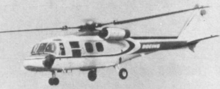
A competitive evaluation of the YUH-60A and YUH-61A was conducted from 1975, and the Sikorsky entrant was judged the winner in December 1976. All three YUH-61A prototypes were returned to Boeing-Vertol shortly after. Of the three prototypes built, one was modified for the LAMPS III programme as a ‘navalized’ version of the Model 237 in the Navy’s LAMPS II competition for a ship-based multi-purpose helicopter, but again lost out to the Sikorsky H-60. It had a four-blade rotor of composite material. Boeing Vertol completed a fourth prototype as the Model 179 civil demonstrator, with accommodation for between 14 and 20 passengers. A 14/20 passenger civil transport (N179BV), it failed to gain commercial interest. Failure to win the Army contract made its production uneconomic, and as a result only the prototype was built. Development of both types was later abandoned. YUH 61A prototypes 73-21656 & 58 were on display at Army Aviation Museum, Ft. Rucker, AL.
Boeing-Vertol Model 179 Engine: 2 x General Electric YT700-GE-700 turboshaft, 1146kW ain rotor diameter: 14.93m Length with rotors turning: 18.13m Height: 4.63m Max take-off weight: 8481kg Empty weight: 4302kg Max speed: 290km/h Cruising speed: 216km/h Hovering ceiling: 1722m Range: 964km
Following the evaluation of submissions by five US helicopter manufacturers, the US Army selected the Boeing Vertol Model 114 as most nearly meeting its requirements for a battlefield mobility helicopter. An initial contract for five YHC-1B pre-production examples was placed in June 1959, but soon after entering service these were redesignated YCH-47A and given the name Chinook.
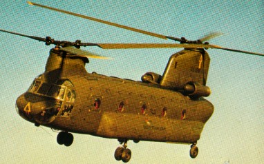
The Model 114 was a larger and more powerful version of the same company’s Model 107 (CH-46 Sea Knight). The non-retractable landing gear is of quadricycle configuratio, with twin wheels on each front unit and single wheels on each rear unit. Oleo-pneumatic shock-absorbers in all units. Rear units fully castoring; power steering on starboard rear unit. All wheels are size 24 x 7.7-VII, with tyres size 8.50-10-III, pressure 4.62 bars. Two single-disc hydraulic brakes each.
The Chinook’s fuselage is built around a cargo bay, in front of which is the flight deck and above it, at either end, the pylons holding the transmission for the two rotors. The two turbine engines are installed on either side of the aft pylon. The fuselage has sealed and compartmented fairing pods on each side of the lower fuselage, extending for almost three-quarters of the fuselage length to supplement the buoyancy of the sealed lower fuselage for water operations.
Self-sealing pressure refuelled crashworthy fuel tanks are in the external fairings on sides of fuselage with a total fixed fuel capacity of 3,899 litres. Provision for up to three additional long-range tanks in cargo area, each of 3,028 litres give a maximum fuel capacity (fixed and auxiliary) of 6,927 litres.
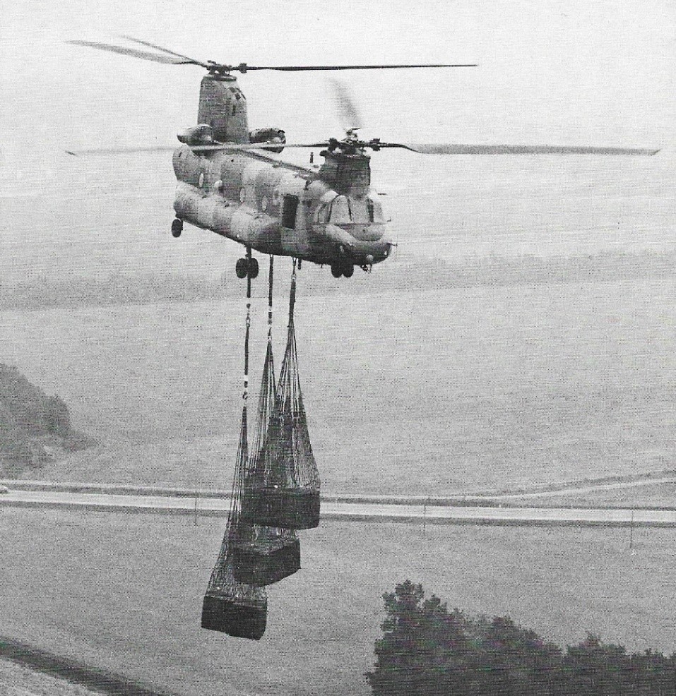
The constant cross-section cabin with side door at front and rear-loading ramp that can be opened in flight. Access to flight deck is from the cabin. Behind the cargo bay is a hydraulically-actuated ramp which greatly facilitates loading and unloading operations. On either side of the fuselage are two large fairings, housing the fuel tanks, landing gear shock absorbers and battery for the electrical system. The cargo bay has a volume of circa 42cu.m and can carry either 44 troops, 24 stretcher cases plus two medical attendants, or a weight of between eight and 11 tonnes. A hoist at the front of the bay can be used for lifting loads vertically through a hatch in the middle of the floor or for lowering items to the ground. The Chinook also has a cargo hook at the center of gravity for carrying slung loads (covered by removable floor panel so that load can be observed in flight), enabling it to operate as a flying crane.
Three cargo hooks are fitted. The centre is capable of lifting 12 tons and the other two 9 tons each.
Two three-blade intermeshing contrarotating tandem rotors, the front rotor turning anti-clockwise, has rotor transmissions driven by connecting shafts from a combiner gearbox. Classic rotor heads with flapping and drag hinges are fitted with 225 rotor rpm. The manually foldable blades, usse Boeing Helicopters VR7 and VR8 aerofoils with cambered leading-edges, and the blades can survive hits from 23mm HEI and API rounds. A rotor brake is optional. To minimize the vibrations transmitted to the fuselage by the rotors, the helicopter has five vibration absorbers, one in the nose, two under the cockpit floor and two inside the aft pylon. Differential fore and aft cyclic is for pitch attitude control, and differential lateral cyclic pitch (from rudder pedals) for directional control. Automatic control to keep fuselage aligned with line of flight. Dual hydraulic rotor pitch-change actuators: secondary hydraulic actuators in control linkage behind flight deck for autopilot/autostabiliser input; autopilot provides stabilisation, attitude hold and outer-loop holds. A 67shp Solar turbine at the base of the aft pylon drives the electric generators and hydraulic pumps. The hydraulic system comprises a utility system, a No.1 flight control system and a No.2 flight control system. Electrical system includes two 40kVA air-cooled alternators driven by transmission drive system. Solar T62-T-2B APU drives a 20kVA generator and hydraulic motor pump, providing electrical and hydraulic power for main engine start and system operation on the ground. Two pilots on the flight deck, with dual controls have a jettisonable door on each side of flight deck. Depending on seating arrangement, 33 to 55 troops can be accommodated in main cabin, or 24 litters plus two attendants, or vehicles and freight. Rear-loading ramp can be left completely or partially open, or can be removed to permit transport of extra-long cargo and in-flight parachute or free-drop delivery of cargo and equipment. Main cabin door, at front on starboard side, comprises upper hinged section which can be opened in flight, and lower section with integral steps. Lower section is jettisonable. Triple external cargo hook system, with centre hook rated to carry maximum load of 11,793kg and the forward and rear hooks 7,711kg each, or 10,433kg in unison. Provisions are installed for a power-down ramp and water dam to permit ramp operation on water, for forward and rear cargo hooks, internal ferry fuel tanks, external rescue hoist, and windscreen washers.
The first YHC-1B made its initial flight on 21 September 1961, by which time the first production contract for CH-47A aircraft had been placed. These were powered initially by 1641kW Lycoming T55-L-5 turboshafts (subsequently by 1976kW T55-L-7 turboshafts), and deliveries of CH-47As began in December 1972. The CH-47B replaced the original model, and was chosen by the US Army as the standard troop transport for the First Cavalry Division (Airmobile). The CH-47B is recognisable by the two thin fins at the base of the rear ramp, and has more powerful 2125kW T55-L-7C turboshafts, redesigned rotor blades and other detail refinements, the first of two prototypes making its first flight during October 1966, with deliveries beginning on 10 May 1967. The CH-47B was followed by the CH-47C (Model 234) which had new 3802shp / 2,796kW T55-L-11A engines, strengthened transmission and new, larger 3,944 litres capacity fuel tanks. The first CH-47C flew on 14 October 1967 and deliveries began in spring 1968. Nine aircraft similar to the CH-47C have been built for the Canadian Armed Forces, under the designation CH-147; deliveries began in September 1974. The CH-147 has the latest safety features and an advanced flight-control system, with a maximum land take-off weight of 22680kg and emergency water take-off weight of 20865kg.
Licence production of the CH-47C has also been undertaken by Ellicotteri Meridionali in Italy since 1970. Agusta, SIAI-Marchetti, and other Italian manufacturers are also involved in this programme. After a number of setbacks, an order was confirmed for 26 CH-47Cs for the Italian Army and the first wholly Italian aircraft were delivered in 1974. The Italian order was followed first by an order for the Iranian Army (initially 20 aircraft) and then for Libya, Morocco, Egypt, Tanzania and Greece.
Under a US Army development programme, one each of the models CH-47A, CH-47B, and CH-47C were stripped down to the basic airframe, and rebuilt to an improved standard to serve as CH-47D prototypes. These upgraded CH-47Ds have more-powerful turboshaft engines and higher-rated transmissions; a redesigned avionics; and many design refinements. They also introduce an auxiliary power unit and a triple hook cargo-suspension system. Following a successful conclusion to flight testing of these prototypes by the US Army, Boeing Vertol started a programme of remanufacturing CH-47As to CH-47D standard, and the first of these was delivered in 1982.
The modernised CH-47D Chinook has been operational with the US Army since February 1984, and offers a payload more than twice that of the original CH-47A. Plans called for the eventual update of 436 CH-47A/B/Cs to D standard. Conversion rate was four per month, and the programme was scheduled to continue until 1993. Changes incorporated include uprated T55-L-712 engines and rotor transmission system, the latter with integral lubrication and cooling. Composite rotor blades are fitted, and avionics and other systems are upgraded. A CH-47D equipped with a retractable 11.6m (38ft) probe successfully completed in-flight refuelling trials with a USAF HC-130 tanker in 1985. Improvements developed for the CH-47D have been built into the current military export version, the CH-47D International Chinook (formerly the Model 414). Spain received six of these between July 1986 and April The 1987, with Bendix RDR-1400 weather radar mounted in the nose.
Under the designation Chinook HC. Mk 1, the Royal Air Force ordered 33 examples similar to the Canadian CH-147. They have British avionics and equipment, and a number of special provisions. The first was handed over in August 1980, and delivery of all 33 was completed during early 1982.
Ultimately, the CH-47 Chinook appeared in a D model with an export variant designated as the CH-47 “International Chinook”.
Boeing 308 Chinook of III Escuadron of Grupo Aereo 7, Argentina
Production by Boeing Vertol of new military Chinooks became limited to orders for the Model 414, which is an international export version and the MH-47E, a Special Forces variant of the CH-47D with night/low flying avionics and an inflight-refuelling probe.
Kawasaki license-produced the CH-47 “D” model as the CH-47J and CH-47JA models. The CH-47J is essen¬tially a CH-47D International Chinook, and a total of 54 were required by the JASDF/JGSDF. Australia signed an order for 12 CH-47C Chinooks in March 1972 and these aircraft went into service with 12 Squadron, RAAF, based at Amberley.
From January 1991, 100 CH-47Ds fitted with engine air particle separator (also available for RAF variant). Standard in MH-47E and optional in International Chinook are two AlliedSignal T55-L-714 turboshafts, each with a standard power rating of 3,108kW continuous and emergency rating of 3,629kW. CH-47SD has T55-L-714A turboshafts with maximum continuous rating of 3,039kW. FADEC installed on late production CH-47Ds and CH-47SD. Normal fuel capacity in CH-47DS and MH-47E is 7,828 litres, but MH-47E can also operate with three long-range tanks in cargo area, each containing 3,028 litres, bringing total fuel capacity to 16,913 litres. CH-47D SOA and MH-47E have 8.97m refuelling probe on starboard side of forward fuselage. US Army modernized some 300 of their 431 D-models to CH-47F standard with more powerful engines, as well as vibration reduction, improved avionics and digital mission systems and map display. The CH-47F first flew early in July 2001.
In late 1965, the first Armed/Armoured Chinook (ACH-47) was officially rolled out and testing was begun. The Armed/Armoured Chinook mounts an array of armament, as well as armor to protect the crew and vital parts of the aircraft against heavy calibre ground fire. Mounted on the nose was an M-5 40mm Automatic Grenade Launcher. This turret-mounted weapon was controlled by the copilot, who was able to cover an extensive area on either side of the flight path. Complementing this nose turret, pylons on each side of the aircraft carried fixed forward-firing weapons including a 22mm gun and either a 19-round 2.75 inch rocket pod, or a 7.62mm high-rate-of-fire Gatling machine-gun. The sides of the aircraft were protected by four gunners stationed two to either side of the cabin. Each of these gunners was provided with either a 7.62mm or 12.7mm calibre machine-gun on flexible mounts. Another gunner was stationed aft with the same type weapons mounted on the rear loading ramp. From this vantage point, the gunner could protect the aircraft from ground fire after the aircraft had passed. This aircraft carried a ton of expendable munitions. The Armed/Armoured Chinook was provided with a new type of steel armour plate which was built into the crew seats and protected their torsos. Similar in configuration to the CH-47A, three of these were evaluated in Vietnam, but no further examples were built.
Despite their design capability, on one memorable occasion in Vietnam a Chinook evacuated 147 refugees and their possessions in a single flight.
CH-47 Chinook
After the CH-47D, Boeing Vertol completed a project in summer 1978 for a commercial version of the same aircraft, primarily intended for operators of oil platforms but also suitable for the prospecting of remote areas. The airframe of the Model 234 is based on that of the military Chinooks, but has many new features such as fiberglass blades of larger chord in place of metal ones, different-sized fairings along the sides of the fuselage containing fuel, a longer nose to house the weather radar and front landing gearwheels shifted farther forward.
Two versions of the Model 234 were available: Model 234LR – a long-range version with lateral fairings almost twice the size of the original Chinook ones, which have 6360kg fuel capacity, and Model 234UT – a utility version in which the fuel tanks of 1826kg are contained in four smaller fairings level with each wheel. The helicopter can be converted from one version to the other. The three rotor blades are interchangeable and maintenance has been reduced to a minimum, with considerable savings in running costs. The service life of the engines has also been increased to 1800 hours TBO. The rotors of the civil Chinook are powered by two Textron Lycoming AL 5512 turboshafts, pod-mounted on sides of rear rotor pylon, via a combining gearbox and interconnecting shafts which enable both rotors to be driven in emergency by either engine. Each engine has maximum T-O rating of 3,039kW, maximum continuous rating of 2,218.5kW, and 30 minutes contingency rating of 3,247kW.
The passenger compartment of the long-range version has 44 seats arranged in four rows with a central corridor and there is a baggage compartment at the rear of the fuselage; it has a crew of three. The 234LR is fitted with cabin windows similar to those of the Boeing 727 airliner, airliner seats at 84cm pitch, overhead baggage lockers, and a number of other ‘airliner’ features. In all-passenger versions of the 234, a galley and toilet are fitted. A typical mixed combination in the utility version consists of 11 passengers and 7250kg of freight. This version also has a cargo hook at the center of the fuselage capable of lifting up to 12700kg, and external cargoes slung from as many as four separate hooks. Long-range model has two fuel tanks, one in each fuselage side fairing, with total capacity of 7,949 litres. Utility model has two drum-shape internal tanks, with total capacity of 3,702 litres. Extended-range model has both fuselage side and internal drum tanks. Single-point pressure refuelling. The 234LR has more power and greater take-off weight (23133kg with an external load compared with 20865kg of the military model). The helicopter can carry an internal load of 9526kg in the cabin, which is 9.19m long, 2.51m wide, and 1.98m high. The first Commercial Chinook made its maiden flight on 19 August 1980, and FAA and CAA certification came on 19 and 26 June 1981 respectively. The FAA and CAA certificated the 234 LR Combi in the Summer of 1982. In the 10 months since the first flight, two BV 234s completed 425 hrs of testing in 361 flights. It had been certificated at a weight of 48,500 lb / 22,000 kg and a range of 565 nm / 1047 km. The first order for the Boeing Vertol 234 came from British Airways Helicopters in 1978 for three (later increased to six), to meet a requirement for offshore work in the North Sea accepting the first in December 1980. Since then Helicopter Service in Norway and ARCO in Alaska have also put the type in service for offshore support.
The BV.234UT conversion for fire fighting and can carry a 3000 USG bucket as an underslung load. There are two 500 USG fuel tanks installed inside the fuselage, but 20 seats are retained.
Total 735 CH-47A/B/C built and 479 CH-47D/MH-47E conversions authorised for US Army. Another 166 built by Boeing for export customers together with 45 kits. Agusta (Meridionali) production totals 136, with Kawasaki having built 54 by January 1999. Total Chinook orders, including civil, amount to 1,155. As well as for the US Army, the Chinook has been built for the Royal Australian Air Force (12) and the Spanish Ejercito del Aire (12), and others have been sold to Argentina, and Thailand.
CH-47A: Initial production version, powered by two 1,640kW Lycoming T55-L-5 or 1,976kW T55-L-7 turboshaft engines. Total 354 built for US Army.
CH-47B: Developed version with 2,125kW T55-L-7C turboshaft engines, redesigned rotor blades with cambered leading-edge, blunted rear rotor pylon, and strakes along ramp and fuselage for improved flying qualities. First of two prototypes flew for the first time early October 1966. Deliveries began 10 May 1967. Total 108 built for US Army.
CH-47C: Developed version with uprated transmissions and 2,796kW T55-L-11A; integral fuel capacity increased to 3,944 litres; first flight 14 October 1967; 270 delivered to US Army from Spring 1968; 182 US Army CH-47Cs retrofitted with composite rotor blades; integral spar inspection system (ISIS) introduced 1973 together with crashworthy fuel system retrofit kit. Transmissions of some As and Bs upgraded to CH-47C standard. Agusta (Meridionali) built 136 by 31 December 1995.
CH-47D: US Army contract to modify one each of CH-47A, B and C to prototype Ds placed 1976; first flight 11 May 1979; first production contract October 1980; first flight 26 February 1982; first delivery 31 March 1982; initial operational capability (IOC) achieved 28 February 1984. First multiyear production contract awarded 8 April 1985 for 240 aircraft; second multiyear production contract for 144 CH-47Ds awarded 13 January 1989, bringing total CH-47D (and MH-47E) ordered to 472; further two Gulf War attrition replacements authorised August 1992 (these new-build); seven ex-Australian rebuilds funded June 1993 for delivery January to November 1995. CH-47D update included strip down to bare airframe, repair and refurbish, fit AlliedSignal T55-L-712 turboshafts, uprated transmissions with integral lubrication and cooling, composite rotor blades, new flight deck compatible with night vision goggles (NVG), new redundant electrical system, modular hydraulic system, advanced automatic flight control system, improved avionics and survivability equipment, Solar T62-T-2B APU operating hydraulic and electrical systems through accessory gear drive, single-point pressure refuelling, and triple external cargo hooks. Principal external change is large, rectangular air intake in leading-edge of rear sail. Composites account for 10 to 15 per cent of structure. About 300 suppliers involved. Test programme began late 1995 of Chinook with vibration-reducing dynamically tuned fuselage.
MH-47D Special Operations Aircraft: Two battalions equipped with 11 CH-47D SOA fitted with refuelling probes (first refuelling July 1988), thermal imagers, AlliedSignal RDR-1300 weather radar, improved communications and navigation equipment, and two pintle-mounted 7.62mm machine guns. Navigator/commander’s station also fitted.
GCH-47D: At least 12 Chinooks grounded for engineer training.
JCH-47D: Two CH-47Ds modified for special testing.
MH-47E: Special Forces variant; planned procurement 51, deducted from total 472 CH-47D conversions but only 25 received, including 14 not covered by multiyear production contract; prototype development contract 2 December 1987. Prototype (88-0267) flew 1 June 1990; delivered 10 May 1991; initial production aircraft flown 1992. Following mission software problems, deliveries began January 1994; last of 26 (including prototype) received April 1995.
MH-47E has nose of Commercial Chinook to allow for weather radar, if needed; forward landing gear moved 1.02 m (3 ft 4 in) forward to allow for all-composite external fuel pods (also from Commercial Chinook) that double fuel capacity; Brooks & Perkins internal cargo handling system. Chinook HC. Mk 2/2A: RAF version; Mk 1 designation CH47-352; all survivors of original 41 HC. Mk 1s upgraded to HC. Mk 1B; UK MoD authorised Boeing to update 33 (later reduced to 32) Mk 1Bs to Mk 2, equivalent to CH-47D, October 1989; changes include new automatic flight control system, updated modular hydraulics, T55-L-712F power plants with FADEC, stronger transmission, improved Solar 71 kW (95 shp) T62-T-2B APU, airframe reinforcements, low IR paint scheme, long-range fuel system and standardisation of defensive aids package (IR jammers, chaff/flare dispensers, missile approach warning and machine gun mountings). Smiths Industries HUMS being installed. Requirement exists for FLIR. Conversion continued from 1991 to July 1995. Chinook HC. Mk 1B ZA718 began flight testing Chandler Evans/Hawker Siddeley dual-channel FADEC system for Mk 2 in October 1989. Same helicopter to Boeing, March 1991; rolled out as first Mk 2 19 January 1993; arrived RAF Odiham 20 May 1993; C(A) clearance November 1993. Final Mk 1 withdrawn from service, May 1994, at which time 11 Mk 2s received. Further three new-build Mk 2s ordered 1993, for delivery from mid-1995; decision to order further 14 Mks 2A/3 announced March 1995. Mk 2A has dynamically tuned fuselage. Total RAF procurement 58 CH-47C/D/Es. First HC. Mk 2A handed over in USA 6 December 1997; arrived UK for clearance trials 18 December; remainder delivered by end of 1998.
Chinook HC. Mk 3: Eight of 14 additional RAF Chinooks announced March 1995 assigned to Special Forces; configuration similar to MH-47E, including large fuel panniers, weather radar and refuelling probes. First flight mid October 1998; deliveries from March 2000.
HT.17 Chinook: Spanish Army version.
Boeing 414: Export military version; superseded by CH-47D International Chinook.
CH-47D International Chinook: Boeing 414-100 first sold to Japan; Japan Defence Agency ordered two for JGSDF and one for JASDF Spring 1984; first flight (N7425H) January 1986 and, with second machine, delivered to Kawasaki April 1986 for fitting out; co-production arrangement (see under Kawasaki). International Chinook available in four versions with combinations of standard or long-range (MH-47E type) fuel tanks and T55-L-712 SSB or T55-L-714.
CH-47SD ‘Super D’: Latest variant on offer for export; embodies some improvements first installed on the MH-47E for US special operations forces. AlliedSignal T55-L-714A turboshaft with FADEC chosen as standard power plant; single-point pressure refuelling and jettison capability on both sides of aircraft, with fuel contained in two ballistic and crash-resistant tanks; total usable capacity is 7,828 litres (2,068 US gallons; 1,722 Imp gallons); CH-47SD also has Smiths digital fuel quantity gauging system in place of Ragen analogue system. Simplified structure offers benefits in maintainability and reliability. CH-47SD also incorporates modernised NVG-compatible cockpit with avionics control management system (ACMS), utilising proven military and commercial off-the-shelf equipment on single console to reduce pilot workload and with provisions for growth. Avionics suite is comparable to that of baseline CH-47D, but features two embedded INS/GPS units as well as AN/ARN-147 VOR/ILS and AN/ARN-149 ADF, plus space and power provisions for Tacan. Rollout scheduled for 31 October 1999.
CH-47F Improved Cargo Helicopter (ICH): Boeing programme for improved Chinook configuration for US Army involving the development and production of a new version that will remain operational and cost-effective until a new cargo helicopter is developed between 2015 and 2020 under the current Army Aviation Modernisation Plan.
234 LR Long Range: About twice CH-47 fuel load in composites tanks attached to fuselage flanks with anti-vibration mounts; flight deck floor on shockmounts; 44-passenger interior (on shockmounts), with toilet and galley, based on Boeing airliners; walk-on baggage bins on rear ramp; alternative mixed passenger/cargo or all-cargo layouts.
234 ER Extended Range: Typical configurations are 17 passengers and two tanks for additional 1,621km or 32 passengers and single cabin fuel tank; FAA certificated May 1983.
234 UT Utility: External fuel cells replaced by two cylindrical tanks in forward fuselage: FAA supplemental-type certificate October 1981 at maximum gross weight 23,133kg with external loads up to 12,700kg on single hook; approved for 24 passengers and operation at up to 3,660m at full gross weight. No known orders, but several converted to this configuration.
234 MLR Multipurpose Long Range: Similar to 234 LR but with utility interior; can be reconfigured in 8 hours; four men can handle cabin cylindrical fuel tanks and ramp baggage bins.
234-100: Commercial equivalent of CH-47D Chinook, proposed to be built in China under co-production agreement between Boeing and Harbin Aircraft Manufacturing Company (HAMC). Minimum launch commitment set at 10 units, with at least 50 required over a five-year period to make it economically viable.
234 Combi: Firefighting modification by Columbia Helicopters equipped to carry 19 firefighters and equipment, capable of dropping 11,370 litres of water. Also carries 9,854 litre Bambi bucket.
Specifications:
Boeing Vertol Model 114
YHC-1B / YCH-47A Chinook Engines: 2 x 1641kW Lycoming T55-L-5 turboshafts – subsequently 1976kW T55-L-7 turboshafts Fixed fuel capacity: 3,899 lt Long-range fuel: 2 x 3,028 lt Maximum fuel capacity (fixed and auxiliary): 6,927 lt. External cargo hook capacity centre: 11,793kg External cargo hook capacity forward/rear: 7,711kg each Max external load: 10,433kg
CH-47A: Engines: 2 x 1,640kW Lycoming T55-L-5 or 1,976kW T55-L-7 turboshaft engines.
CH-47B Engines: 2 x T55-L-7C turboshafts, 2125kW / 2850 shp Rotor dia: 60 ft 0 in (18.29 m) Length: 99 ft 0 in (30.18 m) Height: 18 ft 7 in (5.67 m) Max TO wt: 40,000 lb (18,144 kg) Max level speed: 144 mph (232 kph)
Model 234 / CH-47C Engines: 2 x 3802shp / 2,796kW T55-L-11A Fuel capacity: 3,944 litres Length: 51 ft. Length with rotors turning: 30.18m Height: 5.68m Rotor dia: 18.29m, 60 ft. Max speed: 286km/h Cruise Speed: 257km/h, 120 knots Ceiling: 15,000 ft. Service ceiling: 3290m Radius of Action internal fuel: 240km Max ROA: 750km Range: 1,420 miles. Seating: 33 fully equipped soldiers Empty weight: 9736kg Max take-off weight: 17463kg Internal load cap: 22,000 lb External load cap: 25,000 lb Crew: 2 pilots, 1 Loadmaster, 1 aircrew
CH-147 Maximum land take-off weight: 22680kg Emergency water take-off weight: 20865kg.
CH-47D Engines: 2 x AlliedSignal T55-L-712 turboshafts, 4431shp APU: Solar T62-T-2B Rotor dia: 18.3 m. Fuselage length: 15.5 m. No. Blades: 2 x 3. Length: 51.02ft (15.55m) Height: 18.93ft (5.77m) Maximum Speed: 180mph (290kmh; 157kts) Maximum Range: 264miles (425km) Rate-of-Climb: 1,522ft/min (464m/min) Service Ceiling: 8,448ft (2,575m) HIGE: 8200 ft. HOGE: 4950 ft Accommodation: 3 + 35 (up to 55) Empty Weight:23,402lbs (10,615kg) Maximum Take-Off Weight: 50,001lbs (22,680kg) Payload: 12,065 kg. Fuel cap: 3900 lt. Crew: 3. Pax: 33.
Model 414 / CH-47D International Chinook Engine: 2 x Textron Lycoming T55-712 SSB, 4431shp. Instant pwr: 2237 kW. MTOW: 24,494 kg. Payload: 10,670 kg. Max speed: 156 kts. HOGE: 10,100 ft. Crew: 2. Pax: 44
CH-47F Chinook Engine: 2 x Honeywell T55-GA-14A-714
Chinook HC. Mk 1
Chinook HC. Mk 1B
Chinook HC. Mk 2 Engines: 2 x T55-L-712F APU: Solar 71 kW (95 shp) T62-T-2B
Chinook Mk 2A
Chinook HC. Mk 2/2A
Chinook Mks 2A/3
Chinook HC. Mk 3
HT.17 Chinook
CH-47 “International Chinook” Engines: 2 x T55-L-712 SSB or T55-L-714
GCH-47D
JCH-47D
MH-47D Special Operations Aircraft
MH-47E Engines: 2 x AlliedSignal T55-L-714 turboshafts, standard power rating of 3,108kW continuous and emergency rating 3,629kW MTOW: 24,494 kg. Payload: 12,284 kg. Normal fuel capacity: 7,828 litres Long-range fuel capacity: 16,913 litres Max speed: 154 kts. Max range: 1136 km. HIGE: 9800 ft. HOGE: 5500 ft. Crew: 2. Pax: 44
CH-47J
CH-47JA
CH-47SD ‘Super D’ Engines: 2 x T55-L-714A turboshafts, maximum continuous rating 3,039kW Normal fuel capacity: 7,828 lt (2,068 US gallons; 1,722 Imp gallons)
Armed/Armoured Chinook / ACH-47 Armament: 1 x M-5 40mm Automatic Grenade Launcher 1 x 22mm gun 1 x 19-round 2.75 inch rocket pod, or 1 x 7.62mm Gatling machine-gun. 5 x 7.62mm or 12.7mm calibre machine-gun
Model 234LR Engines: 2 x Textron Lycoming AL 5512 turboshafts T-O rating of 3,039kW, maximum continuous rating of 2,218.5kW, and 30 minutes contingency rating of 3,247kW. TBO: 4000 hrs. Main rotor: 60 ft. Length: 99 ft. Height: 18.7 ft. Max ramp weight: 48,500 lbs. Max takeoff weight: 48,500 lbs. Standard empty weight: 25,200 lbs. Max useful load: 23,300 lbs. Zero fuel weight: 26,403 lbs. Max landing weight: 48,500 lbs. Max sling load: 28,000 lbs. Max internal load: 9526kg Disc loading: 8.6 lbs/sq.ft. Power loading: 7.2 lbs/hp. Max rate of climb: 1180 fpm. Service ceiling: 8500 ft. Hover in ground effect: 8500 ft. Hover out of ground effect: 2700 ft. Max speed: 145 kts. Normal cruise @ 5000 ft: 135 kts. Fuel flow @ normal cruise: 2650 pph. Endurance @ normal cruise: 5.1 hr. Cabin: 9.19m x 2.51m x 1.98m Max usable fuel: 14,091 lbs / 7,949 lt / 6360kg Passenger capacity; 44
234UT Engines: 2 x Textron Lycoming AL 5512 turboshafts T-O rating of 3,039kW, maximum continuous rating of 2,218.5kW, and 30 minutes contingency rating of 3,247kW. Engine TBO: 1800 hr Rotor diameter: 18.29m Length with rotors turning: 30.18m Height: 5.68m Maximum gross weight: 23,133kg Empty weight: 9576kg Max speed: 269km/h Hovering ceiling: 3155m Service ceiling: 4570m Range: 1010km Fuel capacity: 1826kg / 3,702 lt Cabin: 9.19m x 2.51m x 1.98m Max external load: 12,700kg Passenger: 24 Ceiling: 3,660m
In 1956, Vertol began preliminary design and engineering of a twin-turbine transport helicopter for commercial and military applications. The main objective was to take full advantage of the high power, small size and light weight of the shaft-turbine engines then becoming available. To achieve the best possible hovering performance, the traditional Vertol tandem-rotor layout was retained, and the turbines were mounted above the rear of the cabin, on each side of the aft rotor pylon. This results in maximum unobstructed cabin area and permits the use of a large rear ramp for straight-in loading of vehicles and bulky freight.
Construction of a prototype, designated Model 107, was started in May 1957, and this aircraft flew for the first time on 22 April 1958, powered by two 641kW Lycoming T53 turboshaft engines. It was designed for water landing capability, without the addition of special flotation gear or boat hull design, and was intended to carry 23 to 25 passengers in normal airline standard accommodation.
Vertol 107 No.1
The new Model 107 prototype N74060 with two 877shp Lycoming T53 turbines flew on 12 August 1958.
In July 1958, the US Army ordered 10 Model 107s, designated YHC-1A; seven with the uprated 1065shp General Electric YT58 turbine and three with the Lycoming T53, and a rotor diameter increased by 0.6m.
YHC-1A
The first YHC-1A flew on 27 August 1959, but in the meantime, the US Army had ordered five YHC-1Bs (Model 114 later known as the CH-47 Chinook), a scaled-up variant which was better suited to meet its need for a tactical transport helicopter, and consequently the order for the Model 107 was reduced to only three machines (serials 58-5514 through -5516). These machines were used primarily to familiarize Army flight crews with the capabilities of turbine-powered helicopters, and all three were eventually returned to the manufacturer.
The third of these was later returned to the company which equipped it with 783kW General Electric T58-GE-6 turboshaft engines and rotors of increased diameter, and this derivative was fitted out with a commercial interior as the Model 107-II prototype. This first flew on 25 October 1960. By that time Vertol had become a division of The Boeing Company. The first production model of the airliner spec 107 II followed on 19 May 1961 and FAA certification was received on 26 January 1962, entering scheduled service with New York Airways 1 July that year. Eight helicopters were delivered and began scheduled services between mid town Manhatten and Kennedy and La Guardia aoirports. Following this initial order remaining commercial variants were built by Kawasaki.
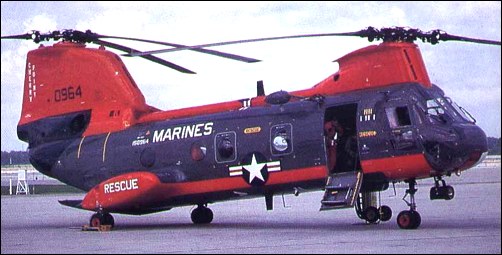
When the US Navy set up a new design competition for a medium-lift transport helicopter in 1960, this was won by the Boeing-Vertol 107M, a modified version of the YHC-1A powered by T58-GE-8 engines in February 1961. A batch of 50 was initially ordered, the first of which was tested in October 1962. Ordered into production under the designation HRB-1 (changed to CH-46A Sea Knight in 1962), the 107M was used for troop transport. The first order for the CH-46A assault transport version for the US Marine Corps was placed in February 1991, with first flight on 16 October 1962. This basic model accommodates a typical total of 26 troops or 15 casualty litters.
In 1963 Sweden bought four more Boeing Vertol 107, bringing to 13 the total ordered for its Air Force and Navy, designated HKP-4.
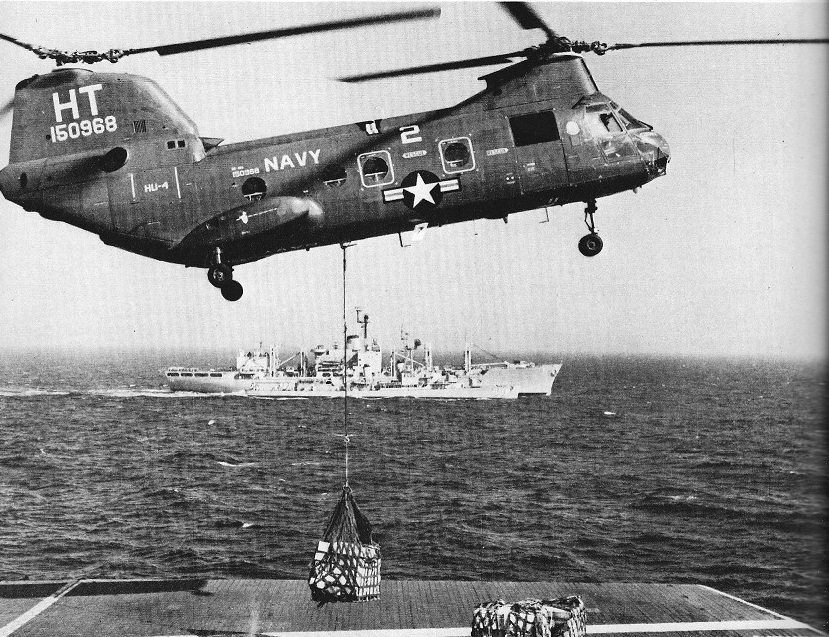
Testing continued into late 1964, with the first US Marine squadrons taking these aircraft into service in early 1965. Four squadrons were operating CH-46As by June 1965 and the type entered service in Vietnam in March 1966, replacing the Sikorsky H-34.During the V ietnam War the Marines also installed a 7.62mm machine gun, which was fired through the cabin door. A total of 498 have been ordered by the Marine Corps and 24 by the US Navy. Several variants have been produced including the CH-46A for the Marines (160); the UH-46A Sea Knight for the US Navy (24) with first deliveries to Utility Helicopter Squadron 1 in July 1964) the CH-46D for the USMC, generally similar to the CH-46A, but with 1044kW T58-GE-10 turboshaft engines (266); the UH-46D for the US Navy (10); the UH-46B for evaluation by the USAF; the RH-46E minehunters for the US Navy, and the CH-46F for the Marines , generally similar to the CH-46D, but with additional avionics (174). The US Navy UH 46 model accommodated a typical total of 26 troops or 15 casualty litters but also able to carry 3175 kg (7,000 lb) of cargo, including vehicles loaded through the full section rear ramp door, for use in the vertrep (vertical replenishment) of ships at sea. Both Sea Knight families can have rescue hoists and are equipped for limited amphibious operation, though they are not intended for sustained alighting on rough seas. Some 669 Sea Knights were built; US Navy and Marine Corps models serving in Operation Desert Storm. A total of 624 models were delivered by 1971, and most surviving examples have been subjected to major update programmes which include fitting glassfibre rotor blades. The best 273 Sea Knights in US Marine Corps service were progressively being rebuilt as CH 46E helicopters with the more powerful 1394kW General Electric T58-GE-16 turboshaft engines, replacing the 1,250 or 1,400 shp (932 or 1044 kW) T58 engines origi¬nally fitted, as well as numerous improvements to improve reliability, res¬cue capability and ability to survive a crash on land or on water. Since 1981, 368 kits were supplied to provide further modifications to im¬prove safety and reduce costs. The CH/UH-46 carries a crew of three, 25 troops and troop commander. Door at front of troop compartment on starboard side. Door is split type; upper half rolls on tracks to stowed position in fuselage crown, lower half is hinged at the bottom and opens outward, with built-in steps. Loading ramp and hatch at rear of fuselage can be opened in flight or on the water. Floor has centre panel stressed for 1,464kg/sq.m. A row of rollers on each side for handling standard military pallets or wire baskets. Outer portion of floor is vehicle treadway stressed for 454kg rubber-tyred wheel loads. Cargo and personnel hoist system includes a variable-speed winch capable of 907kg cable pull at 9m/min for cargo loading or 272kg cable pull at 30m/min for personnel hoisting; it can be operated by one man. A 4,535kg capacity hook for external loads is installed in a cargo hatch in the floor. The cabin is heated by a Janitrol combustion heater and hydraulic system provides 105kg/sq.cm pressure for flying control boost, 210kg/sq.cm for other services. Electrical system includes two 40kVA AC generators and a Leland 200A DC generator. Solar APU provides power for starting and systems check-out. CH-46 has dual stability augmentation systems and automatic trim system. Featuring two three-blade rotors in tandem, rotating in opposite directions. The CH/UH-46 has power-operated blade folding. Power is transmitted from each engine through individually overrunning clutches into the aft transmission, which combines the engine outputs, thereby providing a single power output to the interconnecting shaft which enables both rotors to be driven by either engine. The structure is square-section stressed-skin semi-monocoque structure built primarily of high-strength bare and alclad aluminium alloy. Transverse bulkheads and built-up frames support transmission, power plant and landing gear. Loading ramp forms undersurface of upswept rear fuselage on utility and military models. Baggage container replaces ramp on airliner version. Fuselage is sealed to permit operation from water. Non-retractable tricycle landing gear has twin-wheels on all three units. Oleo-pneumatic shock-absorbers manufactured by Loud (main gear) and Jarry (nose gear). Goodyear tubeless tyres size 8 x 5.5, pressure 10.55kg/sq.cm, on all wheels. Goodyear disc brakes.
Six utility models, almost identical to the CH-46A, were delivered to the RCAF in 1963-4 under the designation CH-113 Labrador, and 12 similar aircraft were built for the Canadian Army during 1964-5, these being designated CH-113A Voyageur. The CH 113 Labrador had a range of over 650 miles (1,050 km). Under a Canadian Armed Forces’ Search And Rescue Capability Upgrade Project (SARCUP), Boeing of Canada was contracted to modify six CH-113s and five CH-113As to an improved SAR standard by mid-1984, with extra fuel, weather radar, a water dam for use of the rear ramp at sea and an APU (auxiliary power unit).
CH-113 Labrador of 103rd Rescue Sqn, Gander
In 1962-3 Boeing Vertol supplied 14 Model 107-IIs to Sweden for service with the air force in the search and rescue role, and with the navy for ASW and minesweeping duties: both of these versions have the designation HKP-4. Sweden uses the Gnome engined HKP 7 version for ASW and mines¬weeping duties.
Kawasaki Heavy Industries obtained a licence in December 1965 to build the Model 107 in Japan in civil and military versions resulting in 12 new versions: the KV-107/11-2 commercial version for passenger transport adopted by Kawasaki, the Thai government and New York Airways; the KV-107/11-3 minehunters; the KV-107/11-4 for tactical transport, 59 of which have been built for the Japanese Ground Self-Defense Force; the KV-107/11-5 rescue version for the Japanese Air Self-Defense Force and the Swedish Navy (38 built); the KV-107/11-7 six-eleven-seat VIP transport version, only one of which has been built for the Thai government; and the KV-107/IIA version for hot climates and high altitudes. Kawasaki obtained in 1965 exclusive rights to manufacture this tandem rotor helicopter and sell it worldwide. The first KV107II obtained Japanese and US type approval in Spring 1968. The 107 Model II standard accommodation is for two pilots, stewardess and 25 passengers in airliner. Seats in eight rows, in pairs on port side and single seats on starboard side (two pairs at rear of cabin) with central aisle. Airliner fitted with parcel rack and a roll-out baggage container, with capacity of approximately 680kg, located in underside of rear fuselage. Ramp of utility model is power-operated on the ground or in flight and can be removed or left open to permit carriage of extra long cargo. The naval KV 107II 3 is a specialized MCM (mine countermeasures) helicopter, of which nine serve with the JMSDF’s 111th Air Wing. This version has up¬rated engines (1,400 shp/1044 kW) in¬stead of 1, 50 shp/932 kW) and com¬prehensive equipment for mine¬sweeping and retrieval, as well as long range tanks, cargo hook and towing gear.
Variants:
107 Model II: Standard commercial version, with two 932kW (1,250 shp) General Electric CT58 turboshaft. Available as an airliner with roll-out rear baggage container or utility model with rear-loading ramp.
CH-46A (formerly HRB-1) Sea Knight: US Marine Corps assault transport version of the 107 Model II powered by two 932kW General Electric T58-GE-8B turboshafts.
CH-46D Sea Knight: Generally similar to CH-46A, but with 1,044kW General Electric T58-GE-10 turboshaft and cambered rotor blades.
CH-46E Sea Knight: Upgraded CH-46A with 1,394kW General Electric T58-GE-16 turboshafts and other modifications including provision of crash attenuating seats for pilot and co-pilot, a crash and combat resistant fuel system and improved rescue system. Initial fleet modifications began in 1977, and the first CH-46E modified at Cherry Point NV, Naval Rework Facility was rolled out 3 August 1977.
CH-46F Sea Knight: Generally similar to CH-46D, with the same engines and rotor blades. Contains additional electronics equipment. All CH-46s delivered since July 1968 were of this version.
UH-46A Sea Knight: Similar to CH-46A. Ordered by US Navy for operation from AFS or AOE combat supply ships to transport supplies, ammunition and missiles as well as aviation spares to combatant vessels under way at sea. Secondary tasks include transfer of personnel and SAR. First deliveries in July 1964.
UH-46D Sea Knight: Generally similar to UH-46A, but with 1,044kW General Electric T58-GE-10 shaft turbine engines and cambered rotor blades. UH-46s delivered since September 1966 were of this version.
CH-113 Labrador: Six utility models delivered to RCAF in 1963-64 for SAR duties. Generally similar to CH-46A. Two 932kW General Electric T58-GE-8B turboshafts. Larger capacity fuel tanks (total 3,408 litres) giving a range of over 1,050km. All six upgraded under Search and Rescue Capability Upgrading Programme (SARCUP).
CH-113A Voyageur: Twelve aircraft in a similar configuration to that of CH-46A, delivered to Canadian Army in 1964-65 as troop and cargo carriers in logistical and tactical missions. Eight upgraded to SARCUP configuration.
Hkp 4C: Built for Royal Swedish Navy (45) and Air Force (10) in 1962-63, with Bristol Siddeley Gnome H.1200 turboshaft engines and fuel tanks of 3,786 litres capacity. Naval version has equipment for anti-submarine and mine countermeasures operations. Since upgraded with Gnome H.1400 turboshafts and new avionics.
HH-46D: Rescue version in service with the US Navy.
UH-46D: Base utility and rescue helicopter. In service with the US Navy.
KV-107/II-2: airline version, with accommodation for two flight crew, a stewardess and 25 passengers; 11 built; improved KV-107/IIA-2 available
KV-107/11-3: mine counter-measures (MCM) version for JMSDF (two), plus seven of the uprated KV-107/11A-3 model
KV-107/II-4: tactical cargo/troop transport for JGSDF with strengthened cabin flooring; 42 supplied as such, with the last of 18 uprated KV-107/ IIA-4 versions delivered in late 1981
KV-107/II-5: designation of 13 long-range SAR helicopters for JASDF; 19 uprated, but otherwise similar aircraft, are designated KV-107/IIA-5, the last three being delivered during 1981; eight KV-107/II-5s supplied to Swedish navy without powerplant, these having Rolls-Royce Gnome H.1200 turboshafts installed in Sweden; Swedish navy designation HKP-4C
KV-107/II-7: designation of one six/eleven-seat VIP transport
KV-107/11A-17: designation of single long-range transport for Tokyo Metropolitan Police Department; has a forward passenger compartment and aft cargo hold
KV-107/II-SM-1: designation of four helicopters equipped as firefighters
YHC-1 Chinook Engines: 2 x GE T58 gas turbines Main rotor: 48’4″ Length: 52’8″ Speed: 155 mph
Model 107 Engines: 2 x Lycoming T53 turboshaft Rotor diameter: 50 ft / 15.24 m Fuselage length: 44 ft 7 in / 13.59 m Overall length: 25.4o m / 83 ft 4 in Height: 5.09 m / 16 ft 9 in Cruise: 120 kt / 222 kph Endurance: 2.2 hr Passenger capacity: 25
Model 107 Engines: 2 x Lycoming T53 turboshaft, 641kW, 877shp Rotor diameter : 60.007 ft / 18.29 m Length : 99.016 ft / 30.18 m Max take off weight : 50406.3 lb / 22860.0 kg Max. speed : 161 kt / 298 km/h Range : 100 nm / 185 km Crew : 2+44
Model 107-II prototype Engines: 2 x General Electric T58-GE-6 turboshaft, 783kW
107 Model II Engines: 2 x General Electric CT58 turboshaft, 932kW (1,250 shp)
YHC-1A Engines: 2 x General Electric YT58 turbine, 1065shp
107M / CH-46A / HRB-1 Sea Knight Engines: 2 x General Electric T58-GE-8B turboshafts, 932kW accommo¬dates 26 troops or 15 casualty litters.
CH-46D Sea Knight: Engines: 2 x General Electric T58-GE-10 turboshaft, 1,044kW External hook capacity: 4,535kg
CH-46E Sea Knight: Engines: two 1,870 shp (1394 kW) General Electric T58 16 turboshafts. Main rotor diameter: 15.24 m (50 ft 0 in) Length overall: 25.70 m (84 ft 4 in) Height: 5.09 m (16 ft 8.5 in) Rotor disc. Area: 364.8 sq.m (3,927.0 sq ft) Fuselage length: 44.82ft (13.66m) Empty weights: 5240kg (11,5851b) Maximum take off: 9706 kg (21,400 lb) External hook capacity: 4,535kg Maximum speed: 267 km/h (166 mph / 144kts) Cruising speed: 193 km/h (120 mph) Range (3000 kg/6,614 1b payload): 175 km (109 miles) Maximum Range: 690miles (1,110km) Rate-of-Climb: 1,715ft/min (523m/min) Service Ceiling: 9,498ft (2,895m; 1.8miles) Accommodation: 3 + 25
CH-46F Sea Knight External hook capacity: 4,535kg
RH-46E
UH-46A Sea Knight External hook capacity: 4,535kg
UH-46B External hook capacity: 4,535kg
UH-46D Sea Knight: Engines: 2 x General Electric T58-GE-10 turboshafts, 1,044kW External hook capacity: 4,535kg
CH-113 Labrador Engines: 2 x General Electric T58-GE-8B turboshafts, 932kW, 1250 shp Rotor dia: 50 ft 0 in (15.24 m) Length: 83 ft 4 in (25.4 m) Height: 16 ft 8.5 in (5.09 m) Max TO wt: 21,400 lb (9707 kg) Max level speed: 157 mph (253 kph) Fuel capacity: 3,408 lt Range: 1,050+km
CH-113A Voyageur
Hkp 4C Engines: 2 x Bristol Siddeley Gnome H.1200 turboshaft (upgraded with Gnome H.1400) Fuel capacity: 3,786 lt
KV-107/IIA-2 Engine: 2 x General Electric CT58-140-1 turboshaft, 1044kW / 1,400 shp Rotor diameter: 15.24m Length with rotors turning: 25.4m Height: 5.09m Max take-off weight: 9707kg Max speed: 254km/h Cruising speed: 241km/h Service ceiling: 5180m Range with max fuel: 1097km Accommodation: 1 stewardess, 25 passengers
KV-107/11-3 Engines: 2 x 1,400 shp/1044 kW
KV-107/IIA-3 Engine: 2 x 1,400 shp General Electric CT58 40 I, or 1,250 shp Ishikawajima Harima CT58 IHI 140 1 turbo¬shaft
KV-107/II-4 Engines: 2 x 1,250 shp/932 kW
KV-107/II-5 Engines: 2 x 1,250 shp/932 kW
KV-107/II-7 Engines: 2 x 1,250 shp/932 kW Seats: six/eleven-seat VIP transport
KV-107/11A-17 Engine: 2 x 1,400 shp General Electric CT58 40 I, or 1,250 shp Ishikawajima Harima CT58 IHI 140 1 turbo¬shaft
KV-107/II-SM-1
KV-107/IIA-SM-2 Engine: 2 x 1,400 shp General Electric CT58 40 I, or 1,250 shp Ishikawajima Harima CT58 IHI 140 1 turbo¬shaft
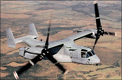
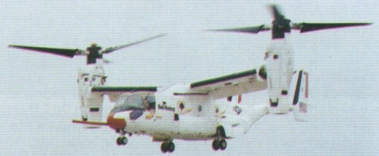
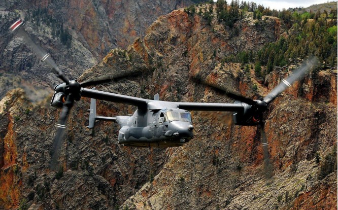
The Bell company brought a history of vertical-lift Tilt-Engine system development to this program when it combined with Boeing in the early 1980s. The company had demonstrated such a system with the XV-3, proving that it was possible to turn wingtip rotors from a vertical position to horizontal, thus providing the thrust to lift the vehicle off the ground and then transition to horizontal flight. The XV-3 was followed by the XV-15, which would closely resemble the V-22, with the XV-15 initially serving as the test vehicle for the V-22. During the early 1980s, the Bell-Boeing competed for the Joint Services Advanced Vertical Lift Aircraft (JVX). Then, on April 26, 1983, the joint team was awarded the contract to begin the preliminary design stage. Initially called the Bell/Boeing-Vertol JVX, the plane would later be given the V-22 Osprey designation, and later, special mission variations carrying the designations of MV-22, HV-22, and CV-22. The 1983 plan called for 1086 of the tri-service VTOLs to be produced with a total procurement cost of $25 billion, with the funding to be shared by the three services. The Navy was to assume the bulk of the obligation with 50 percent contribution. The initial requirement called for the craft to be capable of carrying 24 troops. Power for the Osprey comes from a pair of General Electric T64-GE-717 turboshaft engines, each rated at 6150hp, and the V-22 weighs about 24800kg at maximum take-off weight in a STOL configuration, and about 19840kg in a pure VTOL mode. Its empty weight is just over 14880kg. The rotor diameter is 11.6m, with an overall fuselage length of about 17.4m. With the rotors in the take-off position, the height of the vehicle is just over 6m. The width of the vehicle, with the rotors turning, is almost 26m. Those rotors are capable of rotating through 97 degrees and are constructed of graphite/glassfibre. 33 percent of the weight of the Osprey is fabricated of graphite/glassfibre. The rotors also possess separate cyclic control swashplates for sideways flight and fore-and-aft control during hover. Lateral attitude is maintained by differential rotor thrust. Once the V-22 achieves horizontal flight, the engines have assumed a position parallel to the fuselage.
The V-22 can fly backwards by tilting the rotors back past the 90-degree vertical position. Initial performance requirements for the Osprey were a cruising speed of 480km/h with a range with a full payload of over 1450km. Even though the V-22 carries a cargo designation, it does carry a nose-mounted 12.7mm multi-barrel machine gun. There are redundant systems, along with armor, in critical areas. The composite materials also provide protection, and one engine can power both rotors if required with a cross-coupling capability.
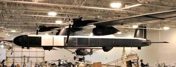
The full-scale development program began in May 1986 with the order for six prototypes. Numbers 1, 3, and 6 were constructed by Bell at Arlington, Texas, and numbers 2, 4, and 5 by Boeing at Wilmington, Delaware.
The first V-22 first flew on 19 March 1989.
The V-22 completed its first transition from propeller to wingborne flight on 14 September 1989.
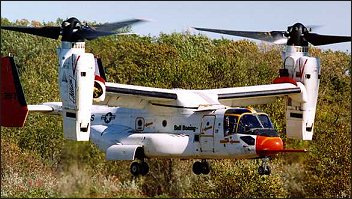
The world’s first operational tilt-rotor transport, the Bell/Boeing’s V 22 Osprey tilt rotor made a successful first flight on 19 March 1989 with “near perfect performance” reported during a series of vertical take offs and landings at Arlington, Texas. The full-scale development program began in May 1986 with the order for six prototypes. Numbers 1, 3, and 6 were constructed by Bell at Arlington, Texas, and numbers 2, 4, and 5 by Boeing at Wilmington, Delaware. The world’s first operational tilt-rotor transport, the Bell/Boeing’s V 22 Osprey tilt rotor made a successful first flight on 19 March 1989 with “near perfect performance” reported during a series of vertical take offs and landings at Arlington, Texas. Wearing grey/green US Marine Corps camouflage, the fourth Bell Boeing V-22 Osprey flew for the first time from Boeing Helicopters flight test centre on 21 December 1989. The flight marked the beginning of V-22 flight test activities at Boeing’s facility in the Delaware Valley. The first flights for the last test vehicle occured in 1991. In 1995, the production of test vehicles resumed with numbers 7 through 10 for vibration, propulsion, USMC, and mating evaluations. Final assembly of the first production V-22 was completed in late 1998. In early 1998, the V-22 accomplished its first night test flight. During the test, the V-22 flew with a neutral density filter which covered the cockpit displays. This allowed the pilots, which were using night vision goggles, to operate the displays in the day mode. Also included in the flight test program was to investigate its capabilities for carry external loads. In one test, the number eight prototype carried a five-ton sling load through the transition phase with a top speed of 425km/h. The test pilot indicated that even though he could feel the load oscillating beneath him, it didn’t affect the craft’s performance. The testing showed that certain loads caused dramatic shifts in the center of gravity of the V-22, which in turn required a change in the attitude of the aircraft. It was determined that that requirement could be accomplished by changing the angle of the engine nacelles. Other tests planned at the time included a sling weight of 6765kg and a Humvee jeep. Early crashes of two prototypes, both in 2000 and resulting in fatalities, nearly did the system in. With pressure mounting to produce, and the general kinks reportedly ironed out, the system was passed for full scale service in 2006. In 1997 low-rate initial production was undertaken for 23 V-22s (called MV-22s) for the USMC. The first MV 22B Osprey tilt-rotor was delivered to the Marines in May 1999. The US Navy has ordered the HV-22 version for SAR duties and fleet logistic support, but cancelled its interest in the Osprey program (HV-22 Combat SAR) in 2001. The projected cost of these first operational V-22s had a unit cost of $32.2 million each, a figure that was down considerably than the $41.8 million projected during the full-scale development program. The plane has attracted international interest, with both Israel and Australia both showing interest in the unique VTOL. Bell is building the wing section, empennage, and powerplant nacelles, while Boeing has the responsibility for the fuselage and landing gear. Bell is also responsible for the final assembly and initial flight tests.
The Boeing Condor was a high-tech test bed reconnaissance aircraft built in the late 1980s. With a wing span of over 200 feet, the Condor is larger than either the Boeing 747 or the Boeing B-52 bomber. The Condor had an un-refuelled flight duration of 80 hours. It was powered by two 175 hp, six-cylinder opposed, twin supercharged, liquid cooled, Continental TSOL-300-2 engines. The aircraft is totally robotic with no pilot. On board computers communicate with computers on the ground via satellite to control all facets of the Condor’s mission.
The Condor set an altitude record for a piston powered aircraft of 67,000 feet, over twelve and a half miles high. The Condor logged over 300 hours of secret missions before its retirement. All of its test flying took place at Moses Lake, Washington.
Very light for its size, the Condor was built of state-of -the-art carbon fiber composite materials, giving the Condor stealth qualities. With a very low radar and heat signature footprint, the Condor was nearly electronically invisible.
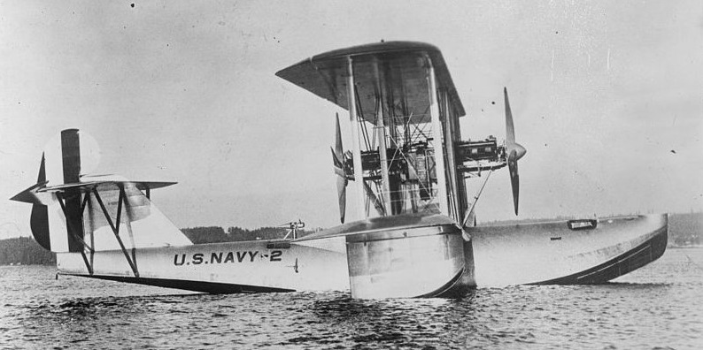
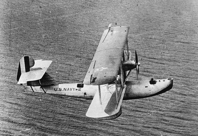
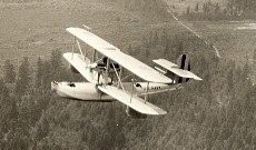
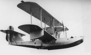
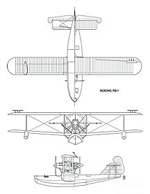
In September 1924, the Naval Aircraft Factory was tasked with designing a long-range twin-engined flying boat, capable of flying the 2,400 mi (3,860 km) between San Francisco and Hawaii. The initial design was carried out by Isaac Laddon, an employee of Consolidated Aircraft, and then passed to Boeing for detailed design and construction. The new flying boat, the Boeing Model 50, was a two-bay biplane of very streamlined design for flying boats of the time. The wings were of metal construction, with wooden wingtips and leading edges. The fuselage had a metal lower part, with the upper half made of laminated wooden frames with a wood veneer covering. Two 800 hp (600 kW) Packard 2A-2500 V12 engines driving four-bladed propellers were mounted in tandem between the wings above the fuselage.
The Boeing Model 50, designated PB-1 by the US Navy, made its maiden flight in August 1925 as A6881. It was intended to use it to lead a pair of Naval Aircraft Factory PN-9s in an attempt to fly to Hawaii on 31 August 1925, but engine trouble led to its participation in the flight being cancelled.
PB-1
In 1928, the aircraft was modified by the Naval Aircraft Factory, its Packard engines were replaced by two 500 hp (370 kW) geared Pratt & Whitney R-1690 Hornet radial engines, leading to the new designation PB-2.
Although the aircraft was a prototype the U. S. Navy did not distinguish between experimental and operational aircraft at that time so the aircraft was never designated XPB-1 or XPB-2.
XPB-1 Engines: 2 × Packard 2A-2500, 800 hp (600 kW) each Length: 59 ft 4.5 in (18.098 m) Wingspan: 87 ft 6 in (26.67 m) Wing area: 1,801 sq ft (167.3 m2) Airfoil: Clark Y Height: 20 ft 10 in (6.35 m) Empty weight: 11,551 lb (5,239 kg) Gross weight: 26,882 lb (12,193 kg) Maximum speed: 97 kn; 180 km/h (112 mph) Cruise speed: 82 kn; 151 km/h (94 mph) Service ceiling: 9,000 ft (2,700 m) Range: 2,172 nmi; 4,023 km (2,500 mi) Rate of climb: 4,000 ft/min (20 m/s) Armament: none fitted Crew: 5
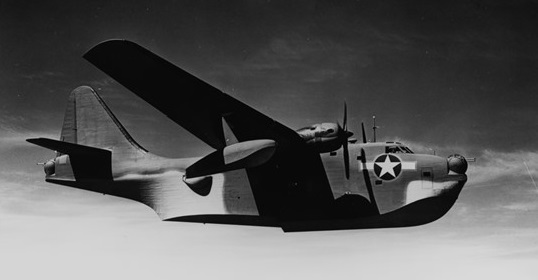
Well before the United States entered World War II, the Navy started a program to develop a long-range flying boat, able to cover the vast expanse of the Pacific Ocean. The Model 344 design offered by Boeing was chosen, and a contract for 57 aircraft was awarded on 29 June 1940.
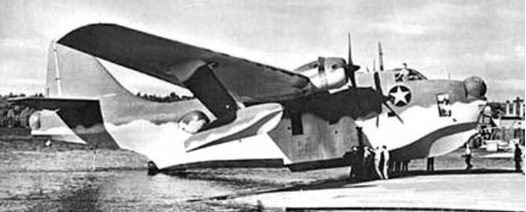
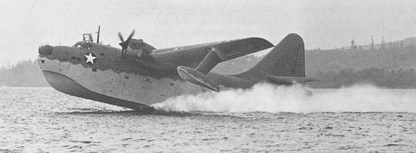
To build the large twin-engined XPBB-1 Sea Ranger (Boeing 344) flying boat Patrol Bomber prototype, Boeing started construction of a new lakeside factory in Renton, Washington, that was owned by the US Navy. The Navy owned 95 acres (38 hectares) on the south shore of Lake Washington in Renton, Wash. The waterfront site provided natural protection from prevailing winds, so it was easier to launch seaplanes directly from the plant. However, the prototype was constructed mostly in Seattle, and was moved to Renton only to be completed.
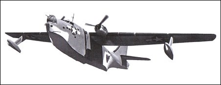
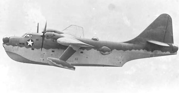
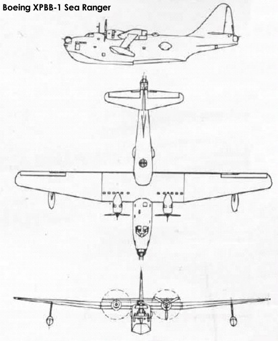
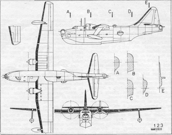
To achieve the desired long range, the PBB became a large aircraft, with a wing span of 139 feet 8½ inches (42.59 m) and a crew of 10. Despite this size, it was powered by just two Wright R-3350 Duplex Cyclone radial engines, driving three-bladed Curtiss Electric propellers. It was the largest twin-engined flying boat flown during World War II. For a flying boat, the PBB was aerodynamically clean, with a cantilever wing set high on the fuselage. The planing bottom had a single step, and the non-retractable outrigger floats were attached to streamlined, cantilever struts. The lower hull was divided in seven watertight compartments, and a short upper deck provided seating for the cockpit crew. The wing of the PBB was constructed in a centre section and two outer panels. The centre section carried the engine nacelles and contained the internal bomb bays, as well as fuel and oil tanks. The outer wing panels contained main and auxiliary, integral fuel tanks.
The defensive armament of the PBB consisted of five powered turrets equipped with Browning .50 M2 machine guns. They were installed in the nose, in the tail, on the upper fuselage just aft of the trailing edge of the wing, and in two waist positions on the rear fuselage. Except for the waist guns, the turrets had two guns each. Offensive armament could consist of up to 20,000 lb of bombs in internal bomb bays in the wing centre section (five bays on each side) or of two Mk.13 or Mk.15 torpedoes slung under the wing centre section.
The 1710 US gallon auxiliary outer and 1565 US gallon inner fuel tanks were intended to be used only in an overload condition, in which the PBB would use catapult-assisted take off to achieve a theoretical range of 11000 miles (17700 km). Normal range using the main fuel tanks was 4245 miles (6830 km).
The PBB was the first aircraft of the Patrol Bomber category built by Boeing for the Navy.
In March 1941 the Navy’s Bureau of Aeronautics asked the Naval Aircraft Factory for a catapult able to launch a PBB-1. The NAF duly prepared a design for a Mark VII catapult that would be able to launch a fifty-ton PBB-1 at a speed of 130 miles per hour. The catapult would be installed on a lighter, so that the flying boat could be lifted onto it with a large crane or hydraulic jacks. However, in the summer of 1942, while development of the Mk.VII catapult was still ongoing, the Navy cancelled the project because it considered JATO assistance at take-off more practical.
The prototype, designated XPBB-1 (hull number 3144), made its first flight on 9 July 1942 from Lake Washington. The aircraft handled very well and was considered technically successful.
The Boeing 25-year tradition of building seaplanes came to an end when the Lone Ranger flew out of Renton for the last time on Oct. 25, 1943, heading for the Navy base in San Diego, Calif.
However, already in 1942 the PBB programme had been cancelled: The need for a long-range flying boat had been reduced by the ability of land planes such as the Consolidated PB4Y to fly long-range missions over the ocean, and construction of a small number of PBB-1s would have a negative impact on the production rate of the B-29. The Navy allowed the Army to use the Renton factory for the production of B-29 bombers, in return for the use of another factory in Kansas.
The single XPBB-1 was handed over to US Navy in 1943, and was used in trials programmes at the naval base in San Diego until 1947, when it was finally retired to the Norfolk Naval Air Station in Virginia. It remained the single example of the type, and was accordingly nicknamed “Lone Ranger”.
The Navy traded the Renton site with the U.S. Army for a plant in Kansas City, Mo., and the Army took over the Renton plant, where Boeing workers subsequently produced 1,119 B-29 bombers. After the war, the Renton plant eventually became a manufacturing facility for Boeing commercial jet transports.
XPBB-1 Sea Ranger Engines: 2 × Wright R-3350-8 Double Cyclone, 2,300 hp (1,716 kW) Wingspan: 139 ft 8½ in (42.59 m) Wing area: 1,826 ft² (169.7 m²) Length: 94 ft 9 in (28.89 m) Height: 34 ft 2 in (10.42 m) Empty weight: 41,531 lb (18,878 kg) Loaded weight: 62,006 lb (28,185 kg) Max. takeoff weight: 101,130 lb (45,968 kg) Maximum speed: 186 knots (214 mph, 345 km/h) at sea level Cruising speed: 158 mph / 254 km / h Range: 6,300 mi (5,500 nm, 10,000 km) (maximum) Normal range: 3,691 NM, (4,245 mi, 6,834 km) Service ceiling: 22,400 ft (6,830 m) Rate of climb: 980 ft/min (4.98 m/s) Endurance: 72 hr Wing loading: 34.0 lb/ft² (166 kg/m²) Power/mass: 0.15 hp/lb (0.24 kW/kg) Armament: 8 × .50 in (12.7 mm) machine guns in bow and tail turrets and waist positions Bombload: 20,000 lb (9,100 kg) Crew: 10
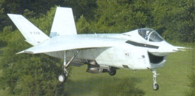
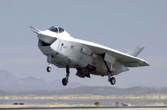
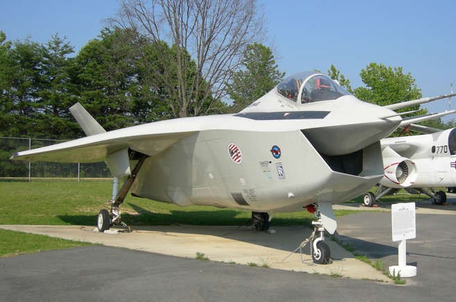
The X-32 STOVL (Short Take-Off and Vertical Landing) technology demonstrator was the Boeing Company’s response to the Department of Defense’s “Joint Strike Fighter Program” beginning in 1994. Boeing’s Joint Strike Fighter (JSF) demonstrator, the X-32A carries its weapons internally in side bays.
The X-32B achieving the first vertical landings following transition from conventional to STOVL flight. The X-32 competed – and failed – against the Lockheed submission, which went on to become the F-35.
Boeing X 32 Joint Strike Fighter Engine: General Electric YF 120 FX, 176580 N Length: 46.916 ft / 14.3 m Height: 13.123 ft / 4.0 m Wingspan: 36.089 ft / 11.0 m Wing area: 538.2 sq.ft / 50.0 sq.m Weight empty: 19999.4 lb / 9070.0 kg Crew: 1 Armament: 1x MG 27mm Mauser, max. 7700kg
Boeing X-32A Engine(s): 2 x Pratt & Whitney F135 turbofan, up to 35,000lbs thrust. Length: 50.75ft (15.47m) Width: 35.99ft (10.97m) Height: 17.32ft (5.28m) Maximum Take-Off Weight:37,920lbs (17,200kg) Maximum Range: 979miles (1,575km) Service Ceiling: 50,000ft (15,240m; 9.5miles) Armament: 1 x 20mm M61A-2 cannon OR 1 x 27mm Mauser BK-27 cannon Maximum external load: 15,000lbs approx. Seats: 1