A motor-driven aeroplane designed by R. H. Botts. The machine was a combination of a circular aeroplane with two sets of two propellers, the screws of each set working in opposite directions. The aeroplane itself is circular, 20ft diam., and attached to two hoops, the outer of steel tubing and the inner, 6ft diam., of wood. In the centre a bamboo framework supported the boiler, engines, and the car. One set of screws (upper 5ft 1in. and lower 6ft 2in diam.) was placed above the car, and these ran on a vertical axis, the thrust upward in both, though rotating oppositely. Fore and aft of the aeroplane the other propellers, of the fan-wheel type, and 6ft 2in diam., worked on a horizontal axis. There were two engines. A cloth-covered rudder was so pivoted as to be able to be set at any angle either vertical or horizontal.
The airship was intended for the St. Louis competition. Total weight of engines 33 lbs.; of complete apparatus with operator (of weight not stated, 214 lbs).
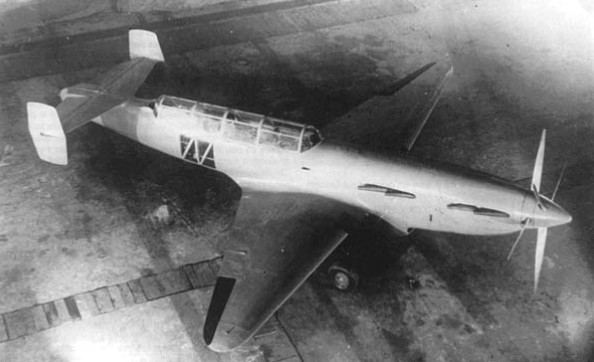
Florov and Borovkov continued with the “Object 10” project airplane that had a clear influence of the I-207 fighter, which is why the literature has sometimes named it I-207/5.
The project for this aircraft was ready for 1940 and envisaged the use of a Shvietsov M-71 engine. The fundamental objective of this new project was to achieve a design capable of eliminating all the difficulties encountered during the I-207 tests.
The aim was to demonstrate the possibility of creating a highly maneuverable biplane fighter with minimal resistance to advance, capable of competing with the best monoplane fighters of the time. The selection of a biplane wing box, according to its creators, should guarantee a more compact aircraft with better visibility for the pilot.
On this occasion and in order to achieve a wing as thin as possible, the builders decided to use a gull-type wing configuration for the upper wing and inverted gull for the lower wing. As in the I-207, the use of any type of bracing or upright was not foreseen. According to calculations the “Object 10” should reach a speed of 650 km / h with a turn time of 14 – 16 seconds.
In an attempt to achieve the highest possible speed, the builders designed from the beginning of the design stage, the use of reactive engines.
As early as July 1939 the engine manufacturer Merkulov had proposed the use of auxiliary ramjets in piston-engined aircraft. These ramjets were characterized by using the same jet fuel as the main power plant. These motors were called DM, acronym for Dopolnitielni Motor or auxiliary motor.
DM motors were designed as short-term supports for those moments in combat when additional speed was required. The first tests of these auxiliary engines were developed on a Polikarpov I-15bis in late 1939. The results were promising and for this reason in 1940 the constructors Borovkov and Florov installed these engines on the I-207/3. The test pilot of Factory No.207, LM Maximov, carried out about twenty flights without difficulties on this plane.
In the “Object 10” project the DM was installed inside the rear fuselage, behind the cockpit. In this way, its installation did not affect performance during the flight under normal conditions. The DM could be switched on by the pilot. For this, some side doors were opened that allowed air access to the engine and it was turned on. An increase in speed was calculated to about 840 km / h.
Unlike the previous models, the tail section was designed as a monocoque duralumin structure with a structure similar to that used in the wing. This was due to the need to reinforce the tail for the installation of the DM engine and to the need to avoid possible fires caused by the hot exhaust gases from the ramjet.
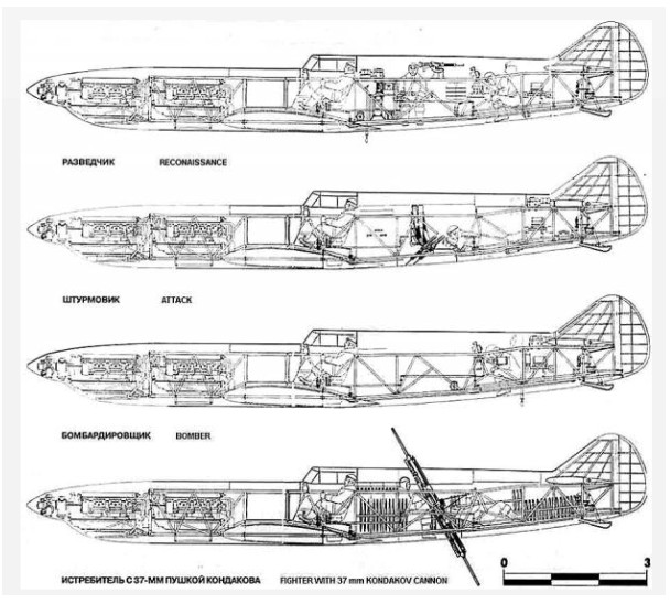
The armament was designed in such a way that it could be added or removed depending on the mission. The initial version was armed with two ShKAS 7.62 mm machine guns and a BS 12.7 mm machine gun, which could be replaced in field conditions by two 23 mm guns in the ground attack version. The armament had to include the possibility of transporting 250 – 500 kg bombs and dropping them accurately during dive on the target.
In the design, 350 – 400 kg were estimated for the armor and the installation of the guns. The cockpit and vital organs of the plane had to be protected. In the fighter version, the pilot’s back was protected by 8.5 mm thick concrete armor capable of defending the pilot from the firing of normal caliber weapons. The frontal armor was provided by the radial motor. This, together with the small dimensions of the plane, guaranteed an important level of safety to the pilot. The fuselage fuel tank was also protected.
A feature was the retractable type tricycle undercarriage. This configuration had been successfully tested by the TsAGI on an SB bomber. As early as 1940, several Soviet models included this type of landing gear in their design. In the case of “Object 10” this decision was forced by the fact that the tail was occupied by Merkulov’s engine.
The “Object 10” project was handed over to the NKAP in the summer of 1940. This project envisaged the use of a Shvietsov M-71 engine and a maximum armament capacity of 1000 kilograms. The armament could be made up of 250 or 100 kilogram bombs, although the possibility of using eight RS-82 reactive rockets under the wings was envisaged. The armament was also composed of two 12.7 mm and two 7.62 mm machine guns.
The cockpit armor comprised a 4 – 4.5mm armored seat plus an 8.5mm cement plate at the rear of the seat.
The project data showed a speed of 658 km / h without the auxiliary engine in the fighter version. The ground attack model had to fly at a speed of 550 km / h.
The project was reviewed by a directed commission for academic BN Yuriev on 3 August 1940, which considered objective the construction of the aircraft in its hunting version high manoeuvrability and in its version with two FAB-250 or four FAB- 100. The commission noted that the actual speed to be reached without the auxiliary engine would be only 605 km / h.
With these results, this variant in general could become an excellent ground attack aircraft. The possibility of using the M-82 engine was also evaluated.
With the start of the war, neither this model nor its development known as “Object 11” were built.
Object 10 Engine: 1x Shvetsov M-71 (1700/2000 hp); 1x Merkulov DM ramjet Wing span: 9.5 m Wing area: 24.0 sq.m Length: 8.35 m Takeoff weight: 3500 kg Wing loading: 146 kg/sq.m Max speed w/out ramjet: 650 km/h Max speed with ramjet: 750-800 km/h Climb to 8000 m (with ramjet active): 8.0 min Flight range: 800 km Armament: 1x 12.7 mm Berezin BS, 2x 7.62 mm ShKAS or 2x 23 mm cannons. Crew: 1
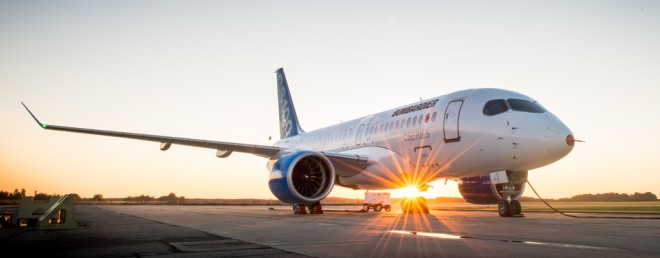
On September 1, 2013 4 Bombardier Aerospace announced that the first CSeries aircraft, Flight Test Vehicle 1 (FTV1), has successfully obtained Transport Canada’s Flight Test Permit, thereby clearing the way for its maiden flight. This follows a series of pre-flight tests including low-speed taxi runs.
“Five years in the making and today, following receipt of Transport Canada’s flight test permit, we are very close to the CSeries airliner’s first flight ” said Mike Arcamone, President, Bombardier Commercial Aircraft.
Designed for the growing 100 to 149 seat market, the 100% new CSeries aircraft family combines advanced materials, leading-edge technology and proven methods to meet commercial airline requirements. Powered by Pratt & Whitney PurePower PW1500G engines, the CSeries aircraft family will offer an extra capacity seating option.
As of June 30, 2013, Bombardier had booked orders and commitments for 388 CSeries aircraft that included firm orders for 177 CSeries airliners.
Bombardier sold the CSeries aircraft to Airbus. The CSeries became known as the A220, the single-aisle jet became a huge success for Airbus.
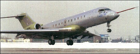
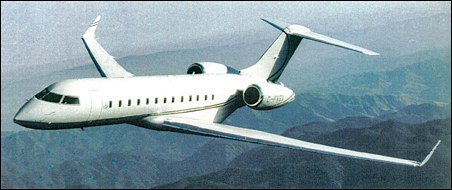
Market and design studies began 1999, announced on 25 October 2001 as the Global 5000. Based on the Global Express, with a 1.83m reduction in fuselage length, and a 2,222km reduction in maximum range, the first flight took place on 7 March 2003 Two aircraft were utilised in the flight test programme.
Bombardier Global 5000 Engines: 2 x 64354 N / 6560 kp Length: 96.752 ft / 29.49 m Height: 24.836 ft / 7.57 m Cabin height: 6.266 ft / 1.91 m Cabin width: 8.169 ft / 2.49 m Cabin length: 42.487 ft / 12.95 m Wingspan: 225.230 ft / 68.65 m Max take off weight: 87714.9 lb / 39780.0 kg Cruising speed (mach): 0.89 mach Range: 4800 nm / 8889 km Passengers: 19
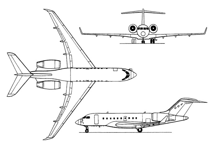
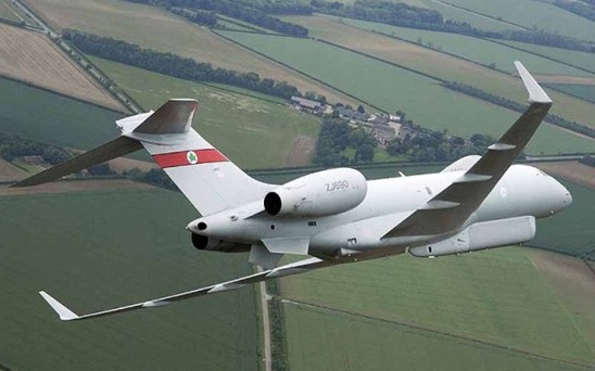
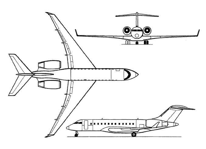
The Bombardier BD-700 Global Express is a twin-engine ultra long range executive jet aircraft with two crew members and up to 19 passengers and 2 flight attendants. Development of the BD-700 started late 1991 and the programme launched on 20 December 1993, the dsign goal was the longest possible range at highest speed from a short runway. A wide-body fuselage, combining the Challenger cabin cross-section with cabin length of the Regional Jet, the prototype rolled out 26 August 1996. Bombardier had 60 firm orders by February 1997.
The first prototype flew on 13 October 1996. On 31 July 1998, the Canadian certification was granted and the first customer delivery was completed on 8 July 1999 to AirFlite Inc of Long Beach, California.
The Bombardier Global Express business jet was certified by the European Joint Aviation Authorities on May 7, 1999. The approval was issued under JAR Part 25, through Change 14. Bombardier reported having 80 orders for the twin-engine jet. Transport Canada and the FAA certified the airplane in 1998.
The range of the Global Express is 11,390 km at a cruise speed of 904 km/h. On 3 August 2001 the first Global Express fitted with the ASTO long range airborne surveillance system flew. The Bombardier BD-700 Global Express is powered by two Rolls-Royce Deutschland BR-710A2-20 turbofans. Total of 91 aircraft were in customer service by 30 September 2002.
Engines: 2 x BMW / Rolls Royce BR 710-48-C2, 66119 N / 6740 kp Wingspan: 91.896 ft / 28.01 m Wing area: 1021.934 sq.ft / 94.94 sq.m Length: 98.983 ft / 30.17 m Height: 25.0 ft / 7.62 m Max take off weight: 93395.0 lb / 42356.0 kg Weight empty: 48510.0 lb / 22000.0 kg Max. speed: 505 kts / 935 km/h Cruising speed: 475 kts / 880 km/h Service ceiling: 51001 ft / 15545 m Wing load: 91.43 lb/sq.ft / 446.0 kg/sq.m Maximum range: 6500 nm / 12038 km Range: 6318 nm / 11700 km Crew: 2 Payload: 8-19 pax (max. 3266kg)
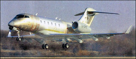
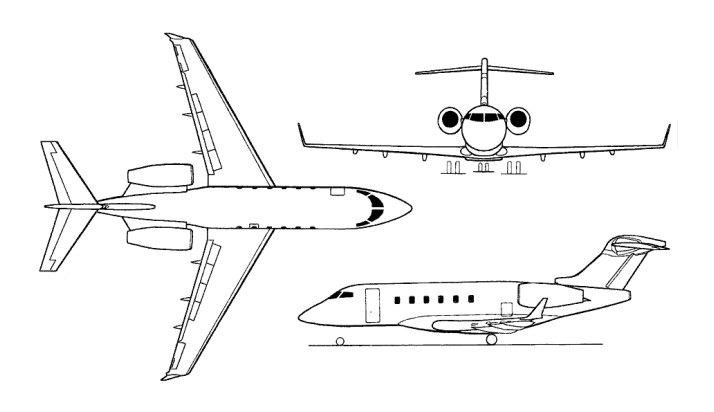
Design study, then known as ‘Bombardier Model 70’, revealed at the Paris Air Show in June 1997; initially named Continental. On 14 August 2001 the first Bombardier Aerospace Continental Jet (factory serial number 20001) took off from Bombardier Learjet facilities at Wichita, and reached 17,500 ft and a speed of 210 kts. Renamed Challenger 300 on 8 September 2002.
The Bo.108 is a flight test vehicle for advanced systems This also includes subsystems integrated into a new airframe. The first of two prototypes (D-HBOX) first flew on 15 October 1988 powered by two Allison 250-C20R turboshafts. The helicopter initially undertook a flight test programme to assist in the advance of helicopter technology particularly in rotor technology, and the development of dynamic systems, anti-resonance isolation systems, composite structures, electrical and avionic systems, cockpit installations and engine integration.
Fitted with higher-powered Turbomeca TM-319 Arrius IBs engines and equipped with a single-pilot EFIS-based IFR system, the second prototype, nominally stretched by 15cm, flew in June 1991.
The Bo.108 was equipped with two Allison 250 C20-R engines but the engine compartment had been designed to allow other power units such as the Turbomeca TM319 or the Pratt & Whitney PW205B/1.
Bo-108 Engine: 2 x Allison 250-C20R-3 turboshaft, 335kW Main rotor diameter: 10m Length rotors turning: 10.6m Height: 3m Take-off weight: 2500kg Empty weight: 1225kg Cruising speed: 270km/h Ceiling: 5000m Range max fuel: 800km
In 1936 Bolkhovitinov considered the problem of high-speed military aircraft. He choose a layout with two M-103 engines, installed one after the other (tandem) with the transmission on coaxial propellers.
He constructs a paired set of engines, followed by bench testd. Bench tests were promising, so in 1937 under the leadership of Bolkhovitinov a high-speed short-range bomber was conceived, indexed “C” (there were several options for decoding the index: “Stalin,” “Spark,” “Spartacus”).
In parallel with the construction of short-range bomber DB, Bolkhovitinov began the design of another aircraft, equipped with a similar twin powerplant. This a project of high-speed long-range fighter-1 twin engine M-107. This was designated “I”. The development was carried out until the spring of 1941 however, an unexpected obstacle has stopped development of the machine. April 25, 1941 Bolkhovitinov was summoned to a meeting of Deputy People’s Commissar Balandin aviation industry. Present at the meeting, Director Motor Works Lavrent’ev and chief designer of engines Klimov reported the impossibility of creating a two-seat trainer M-107P engines.
The main cause of failure was it was thought that in this engine the elongated shaft at working speeds could have resonance problems. Bolkhovitinov were asked to choose any other type of engine available in the country and to convert it for the project. The designer chose the diesel M-40, and while it was heavy, but consumed half as much fuel.
Change the engine caused change for the whole project. Preliminary survey was conducted during May – June 1941, returning to the designation “C”.
I-1 was then included in the plan of an experimental aircraft in 1941, due to the large similarity of the scheme and design of aircraft with “C”, 2M-103 and “C-2”, equipped with one engine M-103 (front-engine was left in place, but its transmission has been disabled from the second propeller.
In general, the draft I-1 was tested by repeating the “C”, but with a much more powerful Klimov M-107 engines. Different from the prototype were vertical stabilizer and skid. The stabilizer was 4.5 m without end plate.
This fighter was never completed due to the refocusing of the bureau.
The draft I-1 had been identified, many new technological approaches for assembly, riveting and bonding aircraft components, in-flight pilot’s ejection, corresponding to speed range 600-750 km / h. Around mid-1941 TsAGI study of was co-axial propellers completed, with the following conclusions:
Efficiency coaxial propellers at high relative received (large pitch speed, ie, a big step corresponds to a high flight speed) for 2 – 4% higher than the efficiency of a single-screw combinations.
At take-off mode at angles the blade is less than 35 ° coaxial propellers efficiency is somewhat lower than the efficiency of single screw. For large values of the power factor of coaxial rod bolts pas-off mode, more than a single screw rod coated (equivalent of the working surface) equal to the total coverage of coaxial.
In order to power the front and rear screws were the same when you reach maximum efficiency, the angle of the blade rear propeller must be 1 -1,5 ° less than the angle of the front propeller.
Change the distance between the screws combinations to the extent permitted by design considerations (within the width of the blades), a noticeable effect on the value of efficiency does not have,
During the war, however, put into practice the results of the research was not possible.
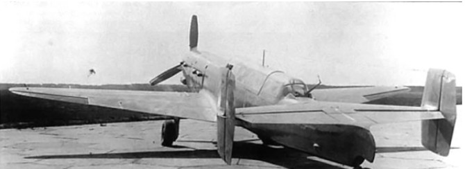
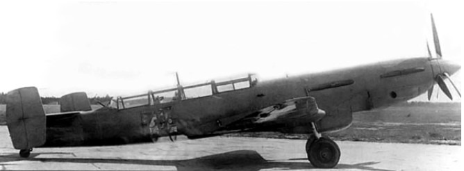
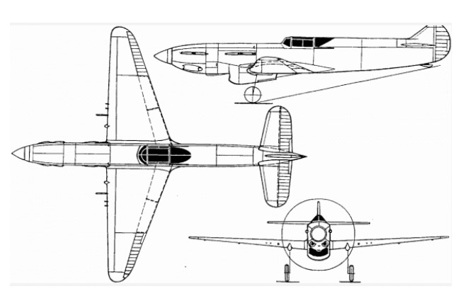
With the intention of creating a high speed light bomber, Viktor Bolkhovitinov designed what is commonly referred to as the Bolkhovitinov S or Sparka. During flight trials the Soviet Air Force (VVS) referred to the aircraft as S-2M-103, for skorostnoy (high speed) with two M-103 engines; however, a number of other designations have been applied over the years. The common “Sparka” designation means twin—because the aircraft had two engines mounted in tandem. Other designations are BBS-1 for blizhniy bombardirovshchik skorostnoy (short range bomber, high-speed), BB for blizhniy bombardovshchik (short range bomber), and LB-S for lyohkiy bombardirovshchik-sparka (light bomber-paired).
The Sparka was a low-wing aircraft of all-aluminum construction with stressed skin. The aircraft had a twin fin tail to increase the rear gunner’s field of fire. The undercarriage was fully retractable; the main gear retracted toward the rear, and the wheels rotated 90 degrees to lie flat within the wings. The pilot and navigator/bombardier/gunner sat in tandem under a long canopy. Between the pilot and second crew member was a small bomb bay for 882 lb (400 kg) of bombs. A plexiglass section on the bottom of the aircraft just aft of the bomb bay provided the bombardier a view of the ground. The aircraft was 43 ft 4 in (13.2 m) long and had a relatively short wingspan of 37 ft 4 in (11.38 m). The Sparka weighed 12,460 lb (5,652 kg).
The Sparka was powered by two Klimov M-103 engines positioned in tandem in the aircraft’s nose. Each engine drove half of the aircraft’s six-blade, coaxial contra-rotating propeller unit. This engine and propeller arrangement was similar to the FIAT AS.6 installed in the Italian MC.72 and the Hispano-Suiza 12Y installed in the French Arsenal VB 10. With this engine arrangement, the front engine drove the rear propeller, and the rear engine drove the front propeller via a drive shaft that ran through the Vee of the front engine.
The Klimov M-103 engine was derived from the M-100, which was a licensed copy of the Hispano-Suiza 12Ybrs. The M-103 had a 5.91 in (150 mm) bore and 6.70 in (170 mm stroke). Total displacement was 2,200 cu in (36.05 L). The engine produced 960 hp (716 kW). A radiator was installed in a large duct just below the rear engine, and it cooled both of the Sparka’s engines.
Bolkhovitinov started design work on the Sparka in 1937, and prototype construction began in July 1938. The aircraft made its first flight in January 1940 (some say late 1939) with B. N. Kudrin at the controls. VVS testing took place from March through July 1940. The Sparka showed good speed, reaching 354 mph (570 km/h). However, the take-off run was excessive, landing speeds were high, and visibility over the nose was impaired. In addition, some trouble was encountered with the rear engine’s propeller drive shaft breaking due to excessive vibrations. Even so, the aircraft received a positive assessment, noting that the installation of the tandem engines eliminated a considerable amount of drag over two separate nacelles.
A new wing was designed with a NACA-230 airfoil section to improve take-off and landing performance. The aircraft was tested with this new wing from September to December 1940, and it did improve the aircraft’s take-off and landing characteristics.
Some say the single engine version was really a separate aircraft (known as S-1) that flew in January 1940 to test the airframe configuration. This seems unlikely because of the time frame involved. The twin-engine Sparka (S-2) would have been nearly complete by the time the single engine airframe test ship first took to the air, making major changes impossible and minor changes difficult. Official trials took place in March 1940.
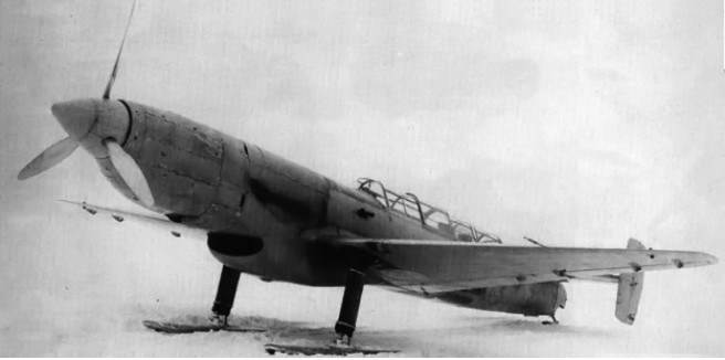
The Sparka was reconfigured for a single 960 hp (716 kW) Klimov M-105P (some say 103P) engine, which was installed in the forward engine bay. The M-105P was a development of the M-103P; both had a smaller bore of 5.83 in (148 mm), but the stroke was unchanged, and could be fitted with a cannon to fire through the engine’s Vee. The aircraft was tested on skis in early 1942 but was underpowered with the single M-105P, attaining a top speed of 249 mph (400 km/h).
Development on the Sparka was abandoned in mid-1941, partially a result of the German invasion. In addition, the factory where the Sparka was built was needed to produce the Petlyakov Pe-2 attack bomber.
I-1 Modification Engine Type 2 PD-107 AM Power, maximal 2 x 1400 HP rated at 2 x 1250 HP Wingspan: 13.80 m Length: 12.96 m Wing area: 22.90 sq.m Empty weight: 2560 kg Maximum take-off weight: 4810 kg Maximum speed SL: 640 km / h Maximum speed: 750 km / h Range: 2000 km Rate of climb: 1000 m / min Service ceiling: 10,000 m Crew: 2 Armament: two 23-mm cannon and four BR 12.7-mm machine gun BS two to four bombs caliber from 100 kg to 250 kg.
S-2M-103 Sparka Engines: two Klimov M-103, 960 hp (716 kW) Prop: six-blade, coaxial contra-rotating Wingspan: 37 ft 4 in (11.38 m) Length: 43 ft 4 in (13.2 m) Weight: 12,460 lb (5,652 kg) Bomb load: 882 lb (400 kg)
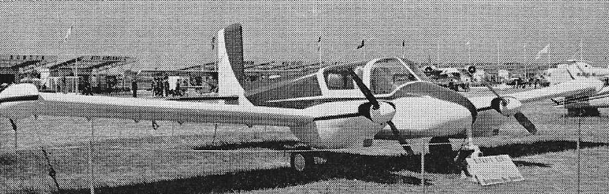
The Boisavia B.260 Anjou was a four-seat twin-engine light aircraft developed in France in the 1950s. It was a low-wing cantilever monoplane of conventional configuration with retractable tricycle undercarriage but fabric-over-tube construction.
Intended by Boisavia as a touring aircraft, it did not find a market and only the single prototype was constructed, first flying on 2 June 1956. At this point, the firm, via NORD, sold the design to SIPA, which modified the design and re-engined it with Lycoming O-360 engines as the Sipavia Anjou, but found that they could not sell it either.
Plans to develop a stretched version with three extra seats and Potez 4D engines were also abandoned.
Avia France says 1 built. But Flight says at least 5 B.260 Anjou were built – or were under construction in 1955 – incl. 2 prototypes by Boisavia and 3 pre-production versions built by SNCAN at Meaulte.
Variants: B.260: Boisavia prototype with Regnier 4L engines (1 built) B.260: 1953 plan was for DH Gipsey Major-powered 4/5-seater B.260: 2 x 170 hp SNECMA-Régnier 4 LO-2 4-cyl inline, B.261: 2 x 190 hp Lycoming O-360-A, 1 B.260 conversion S.261: SIPA designation for the B.261 conversion (1 converted) S.262: Planned seven-seat version (not built)
Specifications: B.260 Engines: 2 × SNECMA licence-built Regnier 4L-02, 127 kW (170 hp) each Wingspan: 12.85 m (42 ft 2 in) Wing area: 21.5 sq.m (231 sq.ft) Length: 7.10 m (23 ft 3 in) Empty weight: 992 kg (2,187 lb) Gross weight: 1,870 kg (4,123 lb) Maximum speed: 260 km/h (160 mph) Range: 1,250 km (780 miles) Service ceiling: 7,125 m (23,370 ft) Rate of climb: 6.0 m/s (1,180 ft/min) Crew: one pilot Capacity: 3 passengers
A LHX request for proposals was issued 21 June 1988 as the centerpiece of the U.S. Army’s aviation modernization plan with the main goal of replacing the entire OH-58s and AH-1 Cobras fleet. Boeing and Sikorsky began collaboration on what later became the RAH-66 in June 1985 and received a 23 month demonstration/validation contract for the demonstration/validation programme on 5 April 1991. The contract was to build four YRAH-66 demonstration/validation prototypes in a 78 month programme, plus static test article (STA) and propulsion system testbed (PSTB). LHTEC T800 engine specified October 1988. LHX designation changed to LH early 1990, then US Army designation RAH-66 Comanche in April 1991. The prototype critical design review, completed in December 1993, authorised production of three YRAH-66 prototypes (the first item for which manufactured in September 1993). At same time, however, further R&D economies under study; December 1994 decision reduced dem/val phase to two prototypes (lacking Longbow/Hellfire capability). Prototype construction began 29 November 1993 with the forward fuselage at Sikorsky, Stratford; Boeing built aft fuselage in Philadelphia. STA airframe delivered to Stratford 1994, at which time PSTB under construction there. PSTB trials commenced in 1995 at West Palm Beach, with 100% torque from both engines achieved during first 10 hours of running. PSTB subsequently suffered failure of left input bevel gear, which disintegrated and punched hole in main gearbox housing during 110% power test; resonance was blamed for the failure. In early 2002, Boeing Sikorsky announced selection of Bridgeport, Connecticut, as the final assembly location for the production RAH-66. Also in 2002, the Joint Program Office moved from Huntsville, Alabama, to Bridgeport. The front and rear sections of the prototype were joined at Stratford on 25 January 1995, and the completed helicopter (94-0327) rolled out on 25 May 1995. Following transfer to Sikorsky’s Development Flight Test Center in West Palm Beach, Florida, during June 1995, the first flight was accomplished on 4 January 1996. Prototype retired from flight test duty on 30 January 2002, by which time it had accumulated 387.1 flight hours in 318 sorties. Aft fuselage section of second prototype (95-0001) was delivered by Boeing to Stratford in early December 1996 for mating with forward fuselage, and the completed helicopter was exhibited at Army Aviation Association’s annual meeting in April 1998 and then to West Palm Beach. Made international debut when displayed statically at Famborough Air Show in September 1998; flew for first time on 30 March 1999. Completed initial test schedule in April 1999, recording 4.9 hours in five sorties before temporary lay-up, due to funding constraints; also used for vertical rate of climb demonstration later in year and will test integrated mission equipment package (ÌÅÐ), including digital avionics, communications, navigation and target acquisition systems. By mid-December 2000, had logged almost 53 flight hours in 50 sorties; these figures had risen to 93 and 103.5 respectively in May 2001 when it was removed from flight status to be prepared for flight testing and validation of ÌÅÐ. This phase of development began on 23 May 2002, when second prototype made first flight with ÌÅÐ and new engines installed. Near-term objectives to be achieved by the second prototype include flight with the night vision pilotage system by October 2002, as well as completion of total weapon system critical design review in May 2003, including the Lockheed Martin Electro-Optical Sensor System (EOSS), which due for delivery in first half of 2003. Engineering and Manufacturing Development (EMD) officially began 1 June 2000, following RAH-66 meeting (on 4 April 2000) seven key Defense Acquisition Board Milestone 2 criteria, including a 107m/min vertical climb rate, a specified detection range for the FLIR sensors, a radar cross-section specification, ballistic vulnerability and tolerance specifications and tower-testing of the selected FCR. Weight reduction effort under way in late 2000, to reduce from current level of about 4,310kg to target weight of 4,218kg. Under original plan, EMD expected to take six years and include production of five RAH-66 specifically for EMD testing, followed by further eight for initial operational test and evaluation (IOT&E) by the US Army. However, EMD contract and plan restructured in mid-2002, at which time IOC forecast to occur in September 2009. The new plan includes a start of low-rate initial production (LRIP) in 2007, with full-rate production set at 60 per year from 2011-12 onwards. First EMD RAH-66 expected to fly in March 2005. In meantime, second YRAH-66 will assume increasing burden of test duty. Production of components for the first EMD RAH-66 began at Boeing’s Philadelphia factory in early 2003, with work on assembling the first empennage beginning on 21 April 2003; on completion, this shipped to Bridgeport and mated with Sikorsky-produced elements. First -801 growth version of T800 turboshaft began bench runs in March 1994; -801 preliminary design review completed May 1993; critical design review March 1995; prototypes originally fitted with less powerful T800-LHT-800 engines, but first flight with definitive -801 engine made on 1 June 2001 by first prototype. Same engine subsequently installed on second prototype in time for resumption of flight test duty in May 2002.
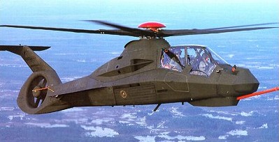
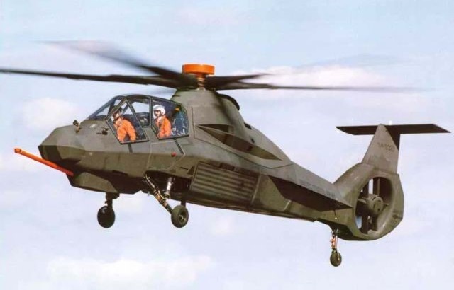
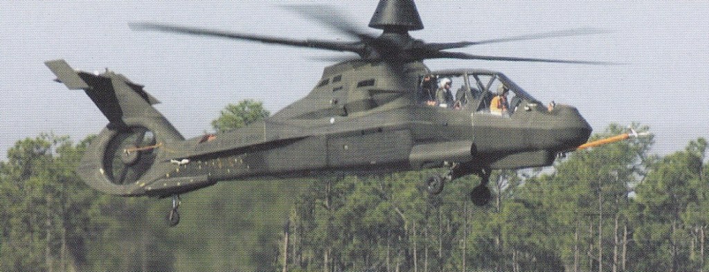
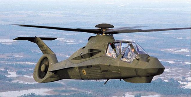
The first combat helicopter designed from outset to have “stealth” features and target acquisition radar. Embodies low-observable (LO) attributes and stated to have radar cross-section (RCS) lower than that of Hellfire missile; frontal RCS reportedly 360 times smaller than AH-64, 250 times smaller than OH-58D and 32 times smaller than OH-58D with mast-mounted sight. Also has quarter of AH-64D’s IR emissions and is six times quieter, head-on. Maximum avionics commonality required with USAF Lockheed Martin F/A-22 Raptor programme. RAH-66 specified empty weight of 3,402kg increased to 3,522kg by early 1992, as result of Army add-ons, including allowance for Longbow radar; mission equipment package has maximum commonality with F/A-22 Raptor technology. Design has faceted appearance for radar reflection; downward-angled engine exhausts; T tail with endplates; eight-blade fan-in-fin shrouded tail rotor; and five-blade all-composites bearingless main rntor system, with latter increased in diameter by 0.3m and gaining noise-reducing anhedral tips on forthcoming EMD aircraft. New rotor incorporating anhedral tips flown for first time on first prototype on 20 July 2001. RAH-66 also features internal weapon stowage. Split torque transmission, obviating need for planetary gearing. Upper part of T tail folds down for air transportation. Detachable stub-wings for additional weapon carriage and/or auxiliary fuel tanks (EFAMS: external fuel and armament management system). Radar, infra-red, acoustic and visual signature requirements set to defeat threats postulated by US Army. Eight deploy able inside Lockheed C-5 Galaxy or four in Boeing C-17 Globemaster III with only removal of main rotor; ready for flight 20 minutes after transport lands. Combat turnround time 13 minutes. Flight controls wree dual triplex fly-by-wire, with sidestick cyclic pitch controllers and normal collective levers. Main rotor blades removable without disconnecting control system. A largely composites airframe and rotor system. Fuselage built around composites internal box-beam; non-load-bearing skin panels, more than half of which can be hinged or removed for access to interior (for example, weapons bay doors can double as maintenance work platforms). Eight-blade Fantail rear rotor operable with 12.7mm calibre bullet hits; or for 30 minutes with one blade missing. Main rotor blades and tail section by Boeing, forward fuselage and final assembly by Sikorsky. Tailwheel type, retractable landing gear, with single wheel on each unit; main units retract aft, with tailwheel retracting forward. Main units can ‘kneel’ for air transportability.
A stealthy multi-sensor platform able to carry out scouting and attack missions, shoot down enemy helicopters and pass data directly to the Longbow Apache attack helicopter, slow funding of the programme encouraged more roles and capabilities to be added, increasing the weight and cost. An early plan envisaged procurement of as many as 5023 Comanches, later reduced to 1400, then 1213 and finally 650. As the numbers fell, the per-unit cost rose from $12.1 million to $58.9 million. Armament was a General Dynamics stowable XM-301 three-barrel 20mm cannon in Giat undernose turret, with up to 500 rounds (320 rounds normal for primary mission) and either 750 or 1,500 rounds per minute firing rates. Aiming coverage of gun is +15 to -45° in elevation and ±120° in azimuth. Integrated retractable aircraft munitions system (IRAMS) features side-opening weapons bay door in each side of fuselage, on each of which can be mounted up to three Hellfire or six Stinger missiles or other weapons. Four more Hellfires or eight Stingers can be deployed from multiple carriers under tip of each optional stub-wing, or auxiliary fuel tank for self-deployment. Will be compatible with Starstreak and Mistral air-to-air missiles. Maximum of 56 Hydra 70mm FFARs or Sura D or Snora 81mm equivalents. All weapons can be fired, and targets designated, from push-buttons on collective and sidestick controllers. Crewed by a Pilot (in front) and WSO in identical stepped cockpits, pressurised for chemical/biological warfare protection. Crew seats resist 11.6m/s vertical crash landing. Powered by two LHTEC T800-LHT-801 turboshafts, each rated at 1,165kW. Transmission rating 1,639kW. Internal fuel capacity 1,142 litres. Two external tanks totalling 3,407 litres for self-deployment; total fuel capacity 4,548 litres. Additional fuel to be contained in two 424 litre tanks in side weapon bays, which in preliminary development in mid-1999. Main rotor tip speed 221m/s; 355rpm. The Comanche had Stealth characteristics achieved by retractable undercarriage and weapons stubs, an angular shape and engine exhaust slots under the fuselage. The propeller hub was entirely covered, and the tail rotor was a ducted fan. The tail surfaces went through many changes to avoid problems with buffeting, eventually being reduced in size and having endplate fins. The ‘flowerpot’ on top of the second prototypes’ main rotor hub contained a version of the Longbow radar.
By February 2001 Boeing had flown a re-designed version of the RAH-66. The new empennage featured vertical and horizontal stabilisers with endplates mounted on the existing shrouded fantail. The entire process took only ten months from initial design to December 2000 first flight.
The US Department of Defence decided to keep the RAH-66 at the technology demonstrator level only. The US Army cancelled the program on 24 February 2004 and give Bell a contract to build the ARH-70 based on the Bell 407. In the end, the expenditure of $8 billion only achieved two flying prototypes and a partially completed test programme.
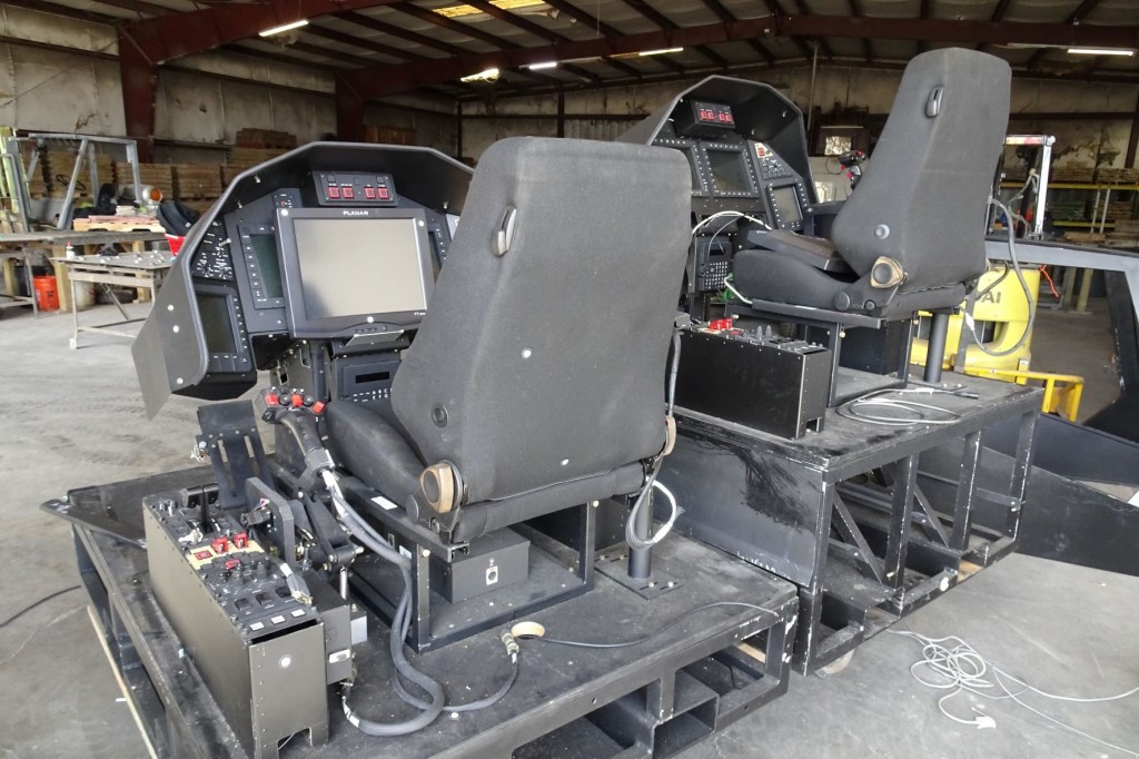
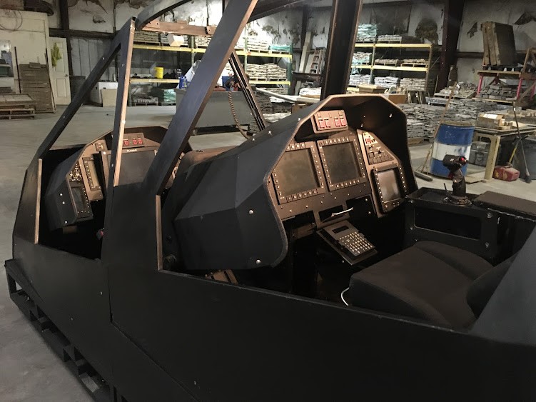
Courtesy John Gwin
One of the Comanche Portable Cockpits used during the RAH-66 resides in a warehouse in Panama City Beach, FL. In 2022.
Courtesy John Gwin
RAH-66 Engines: 2 x LHTEC T800-LHT-801 turboshafts, 1,165kW. Transmission rating 1,639kW. Main rotor diameter: 12.19m Main rotor tip speed: 221m/s Main rotor rpm: 355rpm. Tail rotor diameter: 1.37m Overall length, rotors turning: 14.28m Fuselage length, excl gun barrel: 13.20m Height over tailplane: 3.37m Empty weight: 4,218kg Max useful load: 2,296kg Internal fuel capacity 1,142 lt / 870kg External fuel capacity: 3,407 litres Max fuel capacity: 4,548 litres Take-off weight, primary mission: 5601kg Take-off weight, max alternative: 5850kg Take-off weight (self deployment): 7896kg Max level speed (without radar): 324km/h Max level speed (with radar): 307km/h Cruising speed (without radar): 306km/h Cruising speed (with radar): 276km/h Rate of climb (without radar): 273m/min Rate of climb (with radar): 152m/min Hovering ceiling IGE: 2,745m Hovering ceiling OGE: 1,220m Operational radius, internal fuel: 278km Ferry range with external tanks: 2222km