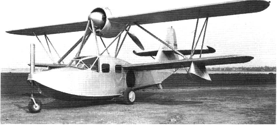
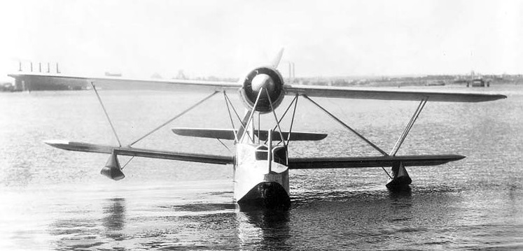
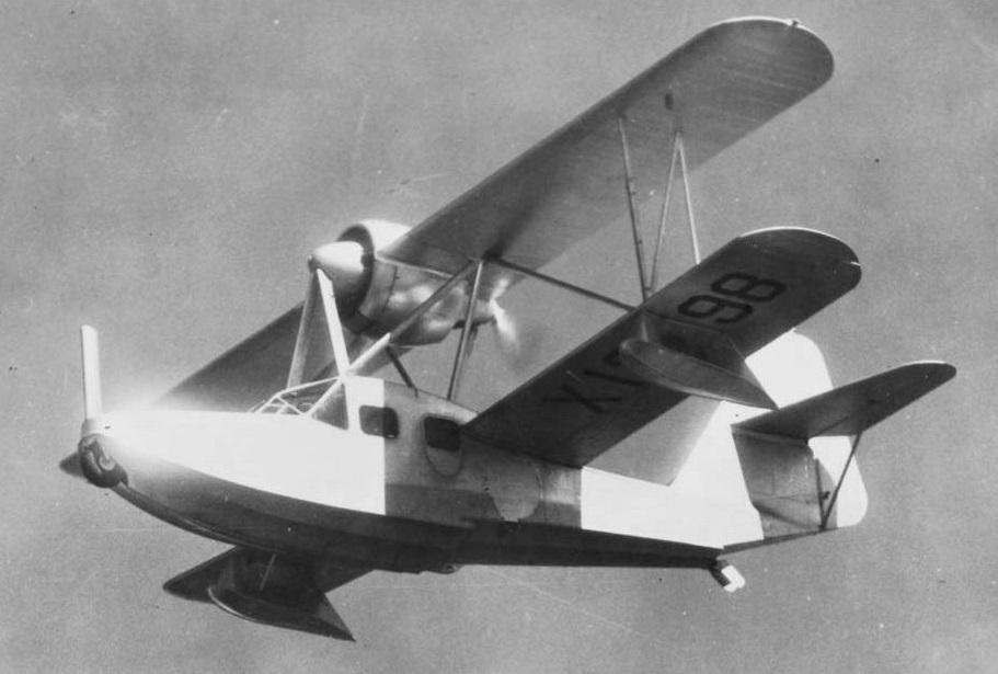
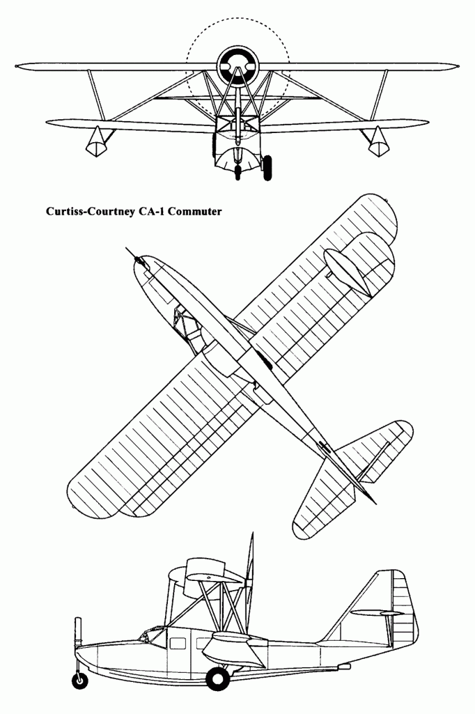
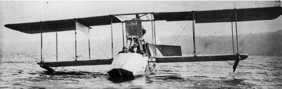
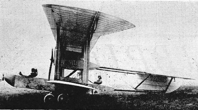
Designed by the British test pilot Frank Courtney, the Curtiss CA-1 (sometimes known as the Commuter or the Courtney Amphibian), was a five-seat amphibian. The CA-1 was powered by a 365 hp (272 kW) Wright 975E-1 radial, cowled and fitted into the leading edge of the top wing driving – through an extension shaft – a pusher propeller. When Wright told Courtney that this could not be done, the Briton went to a non-Curtiss-Wright mechanical workshop and successfully assembled his design.
Possessing a metal hull and wooden wings, the CA-1 had a nose wheel landing gear and an enclosed cabin for the pilot and passengers.
The three prototypes were built at the St. Louis plant, the first flying in 1935.
CA-1 (factory number 101; registration number 13298) in January 1935 received ATC No.2-397, and CA-1 (factory number 102; registration number 11780) in September received ATC 582, aircraft of this type did not go into mass production. Only three aircraft were built and they were all sold in Japan along with the project documentation, designated LXC by the Imperial Japanese Navy Air Service.
Engine: 1 × Wright 975E-1 (J-6-9), 365 hp (272 kW) Wingspan: 40 ft 0 in (12.19 m) Length: 31 ft 0 in (9.45 m) Height: 3.65 m Empty weight: 1352 kg MTOW: 2109 kg Maximum speed: 151 mph (243 km/h; 131 kn) Cruise speed: 125 mph (201 km/h; 109 kn) Stall speed: 60 mph (97 km/h; 52 kn) Range: 550 mi (478 nmi; 885 km) Ceiling: 4267 m Crew: one Capacity: four passengers Baggage: 240 lb (110 kg)
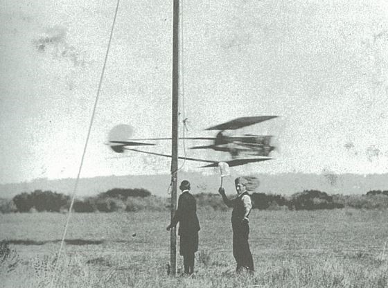
Built to order for Raymond V. Morriss, a Curtiss employee, the single-seat model M made its first flight in January 1914. The Tadpole was the world’s first monoplane flying boat.
Curtiss built the Tadpole to test the aerodynamic relationship between the planning hull and the rigging of the wings. The first variation used a 100 hp Curtiss OX engine and came with the unequal span wings of the early F Boat, but with inset ailerons and several degrees of sweep. One of the devices tested on this aircraft was a set of moveable struts on the upper and lower wing centre sections that enabled incidence to be adjusted. If the wing were adjusted to a negative incidence while the plane was moored, it would not tend to become airborne during high winds. Continuing experiments were carried out with the Tadpole in the winter of 1914 when it was fitted with outrigger skis and flown from a frozen lake.
The 1912 Curtiss-Beachey Speed Tractor was the first of the “modern” Curtiss biplanes, with fabric-covered fuselage, although it was flown uncovered for a while, three-point landing gear with tailskid, and double-surfaced wings, but still using trailing interplane ailerons. Used by Beachey for exhibition work. Design was used for the prototype Curtiss Military Tractor. Powered by a 90 hp Curtiss OX V-8.
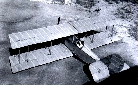
Katherine Stinson in the cockpit of her Curtiss-Stinson Special
The Curtiss-Stinson Special was built by the Curtiss Aeroplane and Motor Company, especially for Katherine Stinson. It was a single-place, single-engine, two-bay biplane intended for exhibition flights. The Special used the fuselage of a Model 10 Speed Scout fighter, new wings, and the tail surfaces of the JN-4 “Jenny.” It was powered by a water-cooled, normally-aspirated, 567.45-cubic-inch-displacement (9.299 liters) Curtiss OXX-6 single-overhead-camshaft (SOHC) 90° V-8 engine, rated at 100 horsepower at 1,400 r.p.m.
Stinson flew between North Island and the Presidio, a straight line distance at 461 miles (742 km).
A replica of this one-of-a-kind airplane is in the Alberta Aviation Museum, Edmonton, Alberta, Canada.
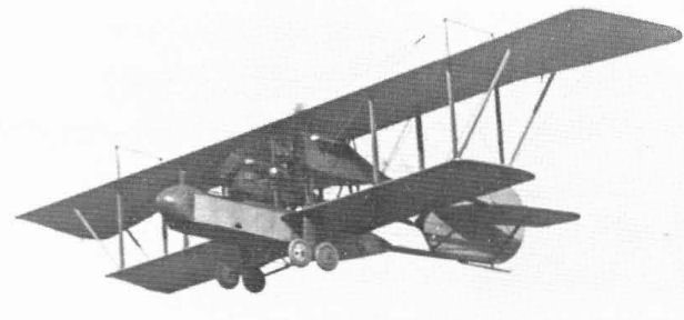
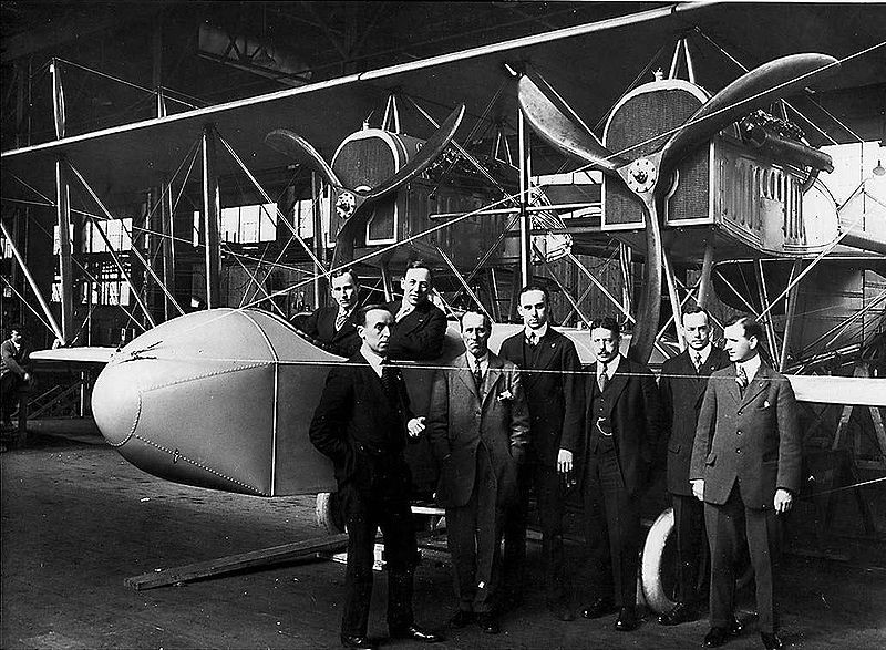
In 1915, Curtiss designed a twin-engined landplane bomber (the first twin-engined Curtiss landplane designed) based on its Curtiss Model H flying boat that had been designed for an attempt to fly across the Atlantic Ocean non-stop, and was in production for Britains’s Royal Naval Air Service (RNAS). The RNAS was interested in Curtiss’s design, and placed an order for a single prototype. As Curtiss’s Hammondsport and Buffalo, New York factories were busy building JN trainers and H-4 flying boats, it was decided to give responsibility for the new bomber, the C-1, to Curtiss’s new Canadian subsidiary, Canadian Aeroplanes Ltd., based at Toronto, giving rise to the name Curtiss Canada.
Curtiss C-1 Canada bomber built and first flown in Toronto, Canada. In the cockpit are chief engineer at Canadian Aeroplanes Ltd. F.G. Erickson (right) and pilot/engineer J.A.D. McCurdy.
The Canada used the uneven span biplane wings and 160 hp (119 kW) Curtiss V-X engines of the H-4 flying boat, but the rest of the design was new. The fuselage was a long nacelle attached to the lower wing, with two gunners sitting side-by-side in an open cockpit in the nose of the nacelle, with the pilot sitting alone in a separate cockpit at the rear of the nacelle, behind the wings. The tail surfaces, with had a single vertical fin, were carried on twin tailbooms extending from the rear of the engine nacelles, with a third, lower, tailboom from the rear of the fuselage nacelle. It had a conventional landing gear with twin, tandem mainwheels and a tailskid. An early form of autopilot, the Sperry stabilizer, was fitted to improve stability for bombing.
Construction of the prototype started in May 1915, and was first flown on 3 September 1915, powered by two 90 hp (67 kW) Curtiss OX-5 engines as the planned V-Xs were unavailable. The C-1 Canada was tested at Long Branch near Toronto, in the Lakeshore area of Etobicoke. Further orders were placed for 102 production aircraft for the RNAS, and another prototype and ten production aircraft for the Royal Flying Corps.
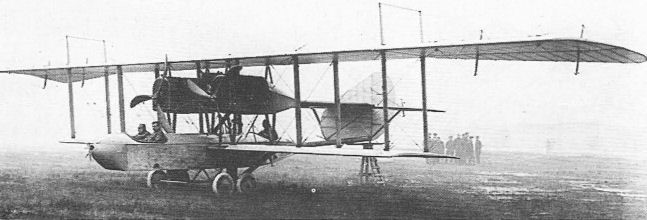
The first Curtiss Canada was delivered by ship to Britain in late 1915, being reassembled at Farnborough for the RFC and received RNAS serial 3700, flying again in January 1916. It was damaged in a crash in February, being rebuilt with modified wings. The wing overhang was now braced with struts instead of the original wires and the C-1 was the first aeroplane to fly with the new streamlined interplane wires (actually tie-rods), developed by the Royal Aircraft Factory, that came to be known as RAF Wires. When tested in April, its performance proved to be poor.
3700 at Farnborough
The adverse report led to the contract for the 100 RNAS aircraft (serials 9500-9599) was cancelled.
While the ten production aircraft for the RFC were delivered un-assembled to Farnborough by July 1916, the RFC had abandoned the Canada, and these aircraft were never re-assembled. The RNAS received one prototype, cancelling its orders as the greatly superior Handley Page O/100 was coming into service.
Powerplant: 2 × Curtiss OX-5 inline, 90 hp each Upper wingspan: 75 ft 10 in (23.11 m) Lower wingspan: 48 ft (15 m) Length: 33 ft 4 in (10.17 m) Height: 15 ft 6 in (4.72 m) Empty weight: 4,700 lb (2,132 kg) Gross weight: 6,300 lb (2,858 kg) Maximum speed: 90 mph (145 km/h; 78 kn) Range: 600 mi (521 nmi; 966 km) Crew: 3 Armament: 2× .303 in (7.7 mm) Lewis guns
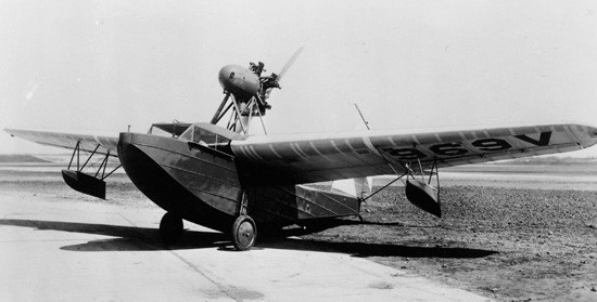
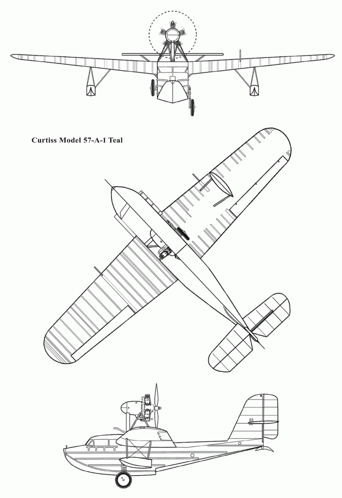
In the late 20s, the Curtiss Airplane and Motor Company developed a Model 57 Teal multi-purpose flying boat. The first A-1 version was completed in 1929.
It was a three-seater with the pusher engine pod-mounted above the wing centre section, equipped with a Wright J-6-5 Whirlwind engine with a power of 165 hp (123 kW).
In 1930, the boat passed flight tests and received a registration N969V. In the same year, the construction of a four-seater B-1 version with a Wright J-6-7 engine with a capacity of 225 hp (168 kW) was started.
Orders for A-1 did not arrive, and then the financial crisis broke out in the USA, as a result of which the company had to stop working on several projects, one of which was Teal. The four-seater B-1 was never completed, although it received a registration number N970V.
Teal A-1 Engine: 1 × Wright J6-5, 165 hp (123 kW) Length: 30 ft 3 in (9.22 m) Wingspan: 45 ft 6 in (13.87 m) Height: 11 ft 6 in (3.50 m) Wing area: 248 ft2 (23.03 m2) Empty weight: 2,135 lb (968 kg) Maximum speed: 99 mph (160 km/h) Cruise speed: 85 mph (137 km/h) Range: 450 miles (724 km) Service ceiling: 10,400 ft (3,170 m) Rate of climb: 400 ft/min (2 m/s) Crew: one Capacity: two passengers
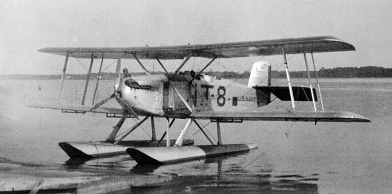
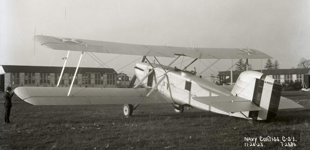
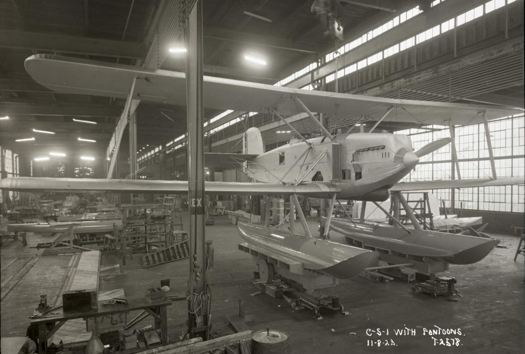
The Curtiss CS (or Model 31) was a reconnaissance and torpedo bomber aircraft used by the United States Navy during the 1920s. It was a large single-engine biplane with single-bay unstaggered wings, the design conventional in all respects other than that the lower wing was of greater span than the upper. The CS was built to allow its undercarriage to be quickly and easily interchangeable between wheeled, tailskid undercarriage, and twin pontoons for operation from water. Provision for the carriage of a torpedo was semi-recessed into the underside of the fuselage, blended in behind an aerodynamic fairing. The pilot and gunner sat in tandem open cockpits, while accommodation inside the fuselage was provided for a third crewmember who served as bombardier and radio operator. This station was also provided with a dorsal hatch aft of the gunner’s position, and a ventral blister aft of the torpedo recess, which was used for aiming bombs or torpedoes.The aircraft was originally designed by the Navy Bureau of Aeronautics. Curtiss won the contract to produce this aircraft, which became the Curtiss CS in the 1922-23 system, standing for Curtiss Scout.
First flying in 1923, Curtiss produced six CS-1 prototypes for the Navy in 1923 powered by 530 hp (395 kW) Wright T-2 engine, which were mostly used for engine tests. Two examples of the improved CS-2 improved version with 600 hp (448 kW) Wright T-3 engine and more fuel were built the following year and set a number of world speed, distance, and endurance records for seaplanes in its class. They were delivered in April 1924 and served with Squadron VT-1. The CS-2 were one converted from CS-1 and two new-built aircraft by Curtiss.
The Navy ordered both the CS-1 and CS-2 into production, but when Curtiss tendered with a price of $32,000 per aircraft, Martin undercut them with a tender of $25,200 for each CS-1 and $19,863 for each CS-2 and won the contract. Curtiss refused to provide full sets of drawings and data to Martin, so Martin-built machines were in part reverse-engineered from a Curtiss-built CS-1 provided by the Navy. These aircraft entered service with squadrons VT-1, VT-2 and VS-1. By the time the Martin-produced aircraft were delivered in 1925–26, the Navy’s designation system had changed, and they entered service as the SC-1 (35 built) and SC-2 (40 built). Martin-built SC-2s suffered from poor handling characteristics and soon earned the nickname “Sea Cow”. The Martin T2M was an alternative designation for the Martin built SC series. Meanwhile, the Naval Aircraft Factory made extensive modifications to the two Curtiss CS-2s leading them to be re-designated CS-3. Curtiss modified a CS-2 with a geared engine, as the CS-3, which formed the basis of the Martin T3M. The Martin XSC-6 was a conversion of an SC-1 with a 730 hp (545 kW) Packard 1A-2500 engine.
Further development of the design was carried out by Martin as the T3M and T4M building 124, and eventually by Great Lakes as the TG.
The XSC-7 was a conversion of a CS-1 with a T-3A engine and increased gross weight.
In all. 83 were built.
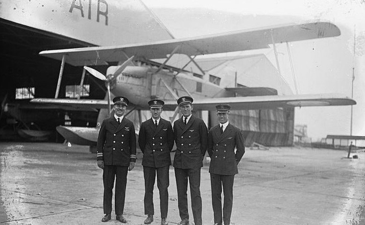
In 1924, the CS-2 was used to break numerous world records for seaplanes in its class in three long-range flights. The first of these took place overnight between 22 and 23 June, when Lt Frank Wead and Lt John D. Price set five records – distance (963.123 mi, 1,544.753 km), duration (13 hours, 23 minutes, 15 seconds), speed over 500 km (73.41 mph, 117.74 km/h), speed over 1,000 km (74.27 mph, 119.12 km/h) and speed over 1,500 km (74.17 mph/118.96 km/h).[1] Between 11 and 12 July, the same pilots would break the distance and duration records again (994.19 mi/1,594.58 km over 14 hours, 53 minutes, 44 seconds).[1] On October 10, these same two records would be exceeded by Lt Andrew Crinkley and Lt Rossmore Lyon in a flight of 1,460 mi (2,342 km) in 20 hours, 28 minutes. While these would have been new world records, the flight was not officially timed, and was therefore not recognized as such.
On September 23, 1925, the U.S. Navy flew 23 Curtiss CS-1 floatplanes to Bay Shore Park on the Chesapeake Bay, 14 miles SE of Baltimore, Maryland, on a Friday with the intention of an air show demonstration before the 1925 Schneider Cup Race on Saturday, but that night gale-force winds broke three-inch mooring and anchor ropes on 17 of the biplanes and they were blown onto shore or dashed against seawalls, destroying seven and damaging ten. The next afternoon’s Baltimore Evening Sun had the headline “Plane Disaster in Harbor Called Hard Blow to Navy” and quoted General William “Billy” Mitchell, who called the loss of the CS-1s “staggering” and blamed it on Navy mismanagement of its aviation program.
By the middle of 1927 CS/ SC were still in use with VT-2B, which had a mix of the Martin produced SC-1s and SC-2s. In addition they were used by VN-3D8 training squadron at Pensacola, which operated 15 SC-1s and 15 SC-2s.
Variants:
Curtiss CS-1 Engine: 525hp Wright T-2 Crew: 3 6 built
Curtiss CS-2 Engine: Wright T-3 2 built
Martin SC-1 35 built
Martin SC-2 Engine: Wright T-3, 585 hp (436 kW) Wingspan: 56 ft 7 in (17.25 m) Wing area: 856 sq ft (79.5 sq.m) Length: 37 ft 9 in (11.51 m) Height: 14 ft 8 in (4.47 m) Empty weight: 5,007 lb (2,271 kg) Gross weight: 8,422 lb (3,820 kg) Maximum speed: 103 mph (166 km/h; 90 kn) at sea level Range: 1,018 mi (885 nmi; 1,638 km) Service ceiling: 8,000 ft (2,400 m) Time to 2,000 ft (610 m): 10 minutes Armament: 1 × rearward-firing machine gun in ring mount Bombload: 1 × 1,618 lb (734 kg) torpedo Crew: 3 40 built
Martin CS-3 CS-2 conversion Engine: geared Wright T-3
CS-4 / CS-5 Naval conversions
XSC-6 Martin SC-1 (A6835) Engine: 730hp Packard 1A-2500
SC-6 The second Martin SC-1 (A6824) Engine: Packard 1A-2500