Doblhoff WNF 342

WHF 342 V-2

The WNF-342 was the work of three engineers – Friedrich von Doblhoff, A.Stepan and Theodor Laufer – at the Wiener Neustadter Flugzeugwerke in Vienna. The operating principle was to use a conventional piston engine driving a compressor to provide a compressed air supply, which, after mixing with fuel, was fed as a combustible mixture up through the rotor hub and out through the three hollow rotor blades to be burnt in tip-mounted combustion chambers, thereby generating thrust.

Doblhoff WNF 342 Article

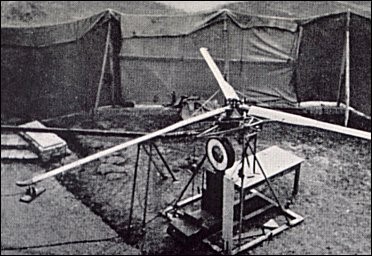
Doblhoff first built, in 1942, a ground test rig to prove the principle of his proposed rotor drive system, consisting basically of a trio of hollow rotor blades mounted on a scaffold with the fuel/air mixture fed through each blade to a small jet unit at the tip. A compressed air tube entered the rotor hub, and vaporized petrol was added by special tubing. The mixture was ignited at the blade tip by an automobile sparking plug. The demonstration proved so successful that the rotor actually ‘took off’ from its moorings, lifting about a yard into the air an anvil that had been attached to it to hold it down. Encouraged by this success, Doblhoff and his team then applied the principle in the small single-seat WNF-342V1 which he hoped would meet a German Navy requirement for an observation helicopter to be carried by submarines or small naval vessels.
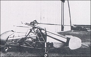
This first prototype, powered by a 60hp Walter Mikron II engine, was flown in spring 1943. The airframe, constructed from welded steel tube and fabric covered, had a gross weight of 360kg, twin tail fins and a tricycle undercarriage. The rotor was fitted with flapping and drag hinges.

WNF-342 V1

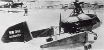
Flight testing revealed the need for rather more side area, but performance was otherwise satisfactory, and when the WNF factory was superficially damaged during an Allied air attack in mid-August 1943 the aircraft was moved to a safer site west of Vienna, at Obergraffendorf. Here a second machine, the WNF-342 V2, was built, being a somewhat heavier aircraft at 460kg gross weight, despite its open-framework fuselage. The main difference lay in the sail-like tail unit, this comprising a large single rectangular fin and an elongated rudder pivoting about a horizontal axis. The 60hp Walter Mikron engine was replaced by a 90hp Walter Mikron engine.
WNF-342 V2

A conventional piston engine drove a compressor, in this particular case the supercharger blower of an Argus 411 engine. The mass flow of compressed air produced by this blower was mixed with fuel before passing through the hollow rotor blades to chrome steel combustion chambers situated at the blade tips. Combustion of this fuel-air mixture occurred at a rate of approximately 280 times per second.

Doblhoff WNF-342 V2

Starting with the V3 machine, increases were made in rotor diameter, and both the V3 and V4 used the extra power of the 140hp BMW Bramo Sh 14A engine to drive the compressor. In all designs, an Argus As 411 supercharger was adapted as a compressor. Before the end of the war, consideration was being given to replacing the compressor system with rotor mounted pulse-jets or even miniature turbo-jets. Within their limited performance, the V1 and V2 machines flew smoothly enough, but serious vibration manifested itself in the V3 machine and ground resonance vibration eventually destroyed it.

WNF-342 V2

Each of the first three machines (V1, V2, and V3) was provided with only a small rear propeller to blow air at the tail surfaces for steering. For the first three machines, although flapping and dragging rotor hinges were provided, no blade pitch-change arrangement was made since this was not required for early tests, vertical control being provided simply by varying the rotor speed.

Experience with the first two machines showed that the high fuel consumption of the tip-jets would make the WNF-342’s operating costs prohibitive, and so a major design change was introduced in the V3 and V4 prototypes. The tip-drive system was retained for take-off, hovering and landing only, a selective clutch enabling the engine (now a 140hp Siemens-Halske Sh.14A radial) to drive a conventional pusher propeller for forward flight while the rotor blades ‘free-wheeled’ in autorotative pitch. To clear this propeller the rotor pylon was raised above the cabin and the tail unit was redesigned as a twin-boom assembly, that of the V3 carrying two end-plate oval fins and rudders while that of the V4 had a single fin and rudder mounted on the tailplane centre. Gross weight of the V3, a single-seater with 9.88m diameter rotors, was 548kg.

By the time the WNF 342 V4 was built a control method had been devised to provide both collective and cyclic pitch control. Each rotor blade was connected to the rotor head by means of a flexibly coupled tube flanked by steel-strip leaf-type spring straps connected to an upper aluminium alloy casting. This upper casting rotated in a lower fixed casting, a seal being provided between the two, and fuel mixture flowed into this hollow assembly to be piped out to each blade. Passing up through the casting was a hollow fixed shaft which carried a bearing for the upper casting and which was flexibly connected to the helicopter framework. Inside this hollow shaft, a solid shaft rotated in a spherically seated bearing to carry the blade pitch control spider at its head. Thus, angular displacement of this solid shaft tilted the spider to give appropriate cyclic pitch control. For collective pitch control, the spider was connected to the solid shaft by means of a pressure regulator connected to the upper casting (containing the pressurized fuel mixture) by a pipeline. The spider was given a vertical movement according to the mixture pressure opposed by springs within the regulator. In addition, collective pitch was governed by the torsional stiffness of the centrifugally-loaded spring straps. When the pilot moved the throttle control, a rapid increase (for example) of mixture pressure and jet thrust followed by an increase in collective pitch ensued, while the rotor rpm remained constant.
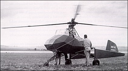
WNF-342 V4

The V4 had a second propeller mounted co-axially to provide thrust for forward flight when clutched to the compressor motor. Thus, by gradual development, the rotor jets (which had a high fuel consumption) were only used for take-off, hovering and landing, and the rotor blades turned by autorotation for forward flight in the manner of an autogyro. The V4 had side-by-side open cockpits for a crew of two.

The V4 was hovered for a total of 25 hours, it was not tested in forward flight above 40 to 48km/h before the programme had to be halted. In April 1945, Soviet troops approaching Vienna caused Doblhoff’s team to withdraw hastily to Zell am See where the V2 and V4 machines were captured by United States’ forces. Doblhoff later accompanying it back to the United States to assist with further tests before joining McDonnell to work on development of the XV-1. Stepan, who had done most of the test flying on the WNF-342, joined Fairey in the United Kingdom after the war, while Laufer went to work for the SNCA du Sud-Ouest in France where he worked on the jet-propelled Djinn.

On September 9, 1946, the General Electric Company (specifically, the Thermal Power Systems Division of its General Engineering and Consulting Laboratory) was permitted by the USAAF to evaluate the WNF 342 V4 in connection with that company’s work on the power plant of the XR-17 helicopter, which would later become the Hughes XH-17. It was shipped by a Fairchild C-82 to Schenectady, New York on December 6, 1946, where it was tested and studied by General Electric under Army Air Force Contract No. W-33-038-AC-16283. This article presents their evaluation report dating from April 30, 1948.

General Electric Company Doblhoff
WNF 342 V4 Evaluation Report

Igor Bensen, one of the primary authors of the report, would go on to perform many test flights of the WNF 342. Unfortunately, he suffered severe spinal injuries when the helicopter was destroyed in a ground resonance accident; these injuries would plague him throughout his life. However, they did not stop him from playing a significant role in the development of the Hughes XH-17 and eventually founding his own company, Bensen Aircraft, which produced a successful line of gyrogliders and autogyros over the course of several decades. Doblhoff was also involved with the XH-17 program, as well as the McDonnell XV-1 convertiplane, among others.

The WNF 342 V4 has been preserved by the Smithsonian Institution, Washington.

Gallery

WNF-342 V1
Engine: 1 Walter Mikron II, 60hp
Weight fully loaded: 360kg
Empty weight: 240kg
Number of seats: 1

WNF-342 V2
Engine: 1 x Walter Mikron, 90hp
Weight fully loaded: 460kg
Empty weight: 340kg
Number of seats: 1

WNF-342 V3
Rotor diameter: 9.88m
Gross weight: 548kg
Seats: 1

WNF 342 V4
Engine: 1 x BMW-Bramo Sh.14A, 105kW / 140 hp
Main rotor area: 78.54 m2 / 845.42 ft2
Main rotor diameter: 9.96m / 32 ft 9¾ in
Fuselage length: 5.07m
Height: 2.40m
Max take-off weight: 640kg / 1,411 lb
Empty weight: 431kg / 948 lb
Max speed: 48km/h / 30 mph
Crew: 2
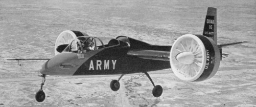
Doak 16 / VZ-4

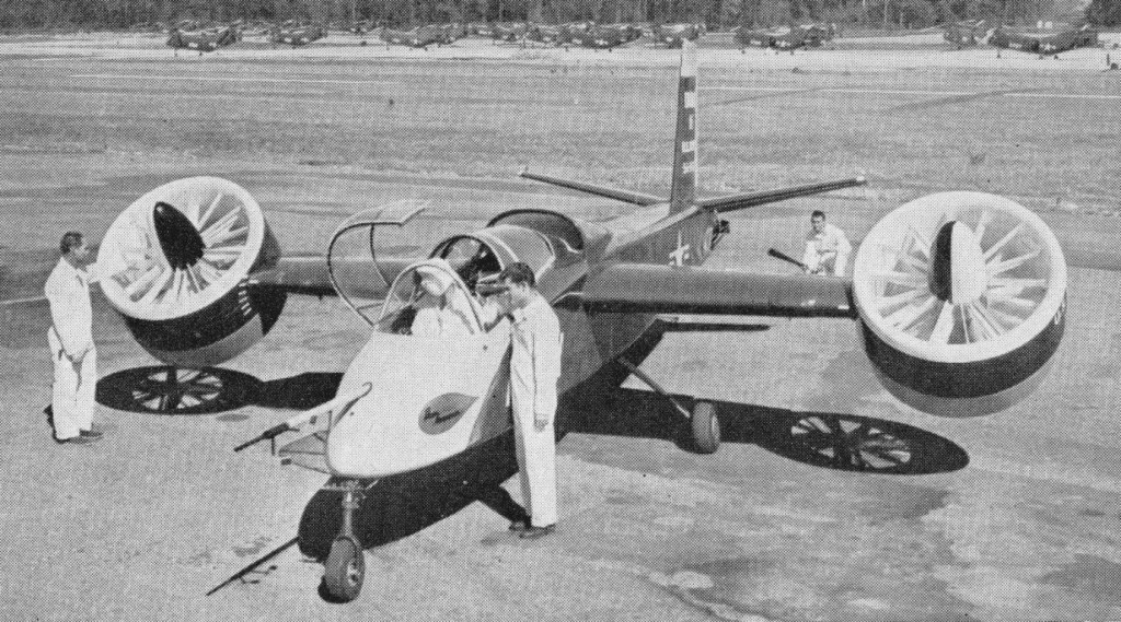
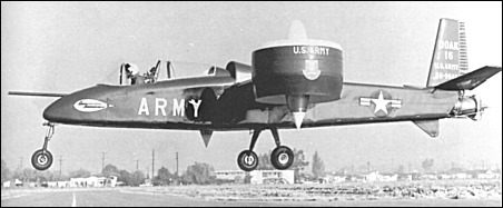
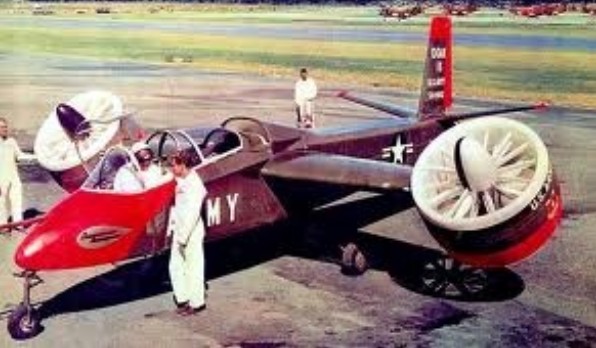
Company president, Edmond R. Doak, had experimented with ducted fan and various other air moving principles since 1935. He first proposed a VTOL aircraft using the tilt duct principle to the military as early as 1950. The Army issued the contract to Doak on April 10, 1956. The U.S. Army Transportation Research and Engineering Command purchased a single Doak 16. The Model 16 made its first flight in February 1958 and the single prototype was put through extensive pre-delivery flight testing and was not officially accepted by the Army until September 1959. Upon acceptance the craft, which had already been allocated the serial number 56-9642, was given the designation VZ-4.

Early 1958

Doak Model 16 was the first VTOL aircraft to demonstrate the tilt duct concept. It was built by the Doak Aircraft Company of Torrance, CA.
The fuselage was constructed of welded steel tubing covered by moulded fiberglass skin from the cockpit forward, while the wings and tail were metal-skinned. The aircraft was designed to accommodate a pilot and observer sitting in tandem, though as far as can be determined the observer’s seat was never actually installed in the prototype.
With a mid-wing, conventional tail, and fixed tricycle landing gear, a single 1000shp Lycoming YT53-L-1 turbine mounted in the fuselage just aft of the cockpit drove two ducted-fan airscrews, one fixed within each rotating wingtip fan assembly. The fans were set in the vertical position for takeoff and landing, and were rotated into the horizontal plane for normal forward flight. Some additional directional stability was provided by routing the turbine exhaust through a set of hinged louvers mounted in the aircraft’s tail.
The cantilever wing and tail unit were of all metal construction. To save development costs, Doak incorporated numerous off the shelf items in the design, such as the landing gear from a Cessna 182, seats from a F-51, duct actuators from T-33 electric flap motors, and the rudder mechanism from an earlier Doak aircraft.

The design empty weight was 900kg with a design gross vertical take-off weight of 1170kg. These grew to 1037kg and 1443kg during the life of the program. To keep weight down, the original specification called for the aircraft fuselage to remain uncovered. However, it subsequently was felt that this would severely limit being able to obtain any meaningful forward speed data, and that the added weight would allow for much more valuable data to be collected.

The wingtip-mounted ducts were five feet in diameter with a four foot inside diameter. Their construction was of aluminum alloy with a fiberglass leading edge section. Eight fixed pitch fiberglass fan blades turned at a maximum fan speed of 4800 rpm. Ahead of the fan in the forward part of the duct were fourteen fiberglass variable inlet guide vanes. The vane angle varied during hover to modulate the thrust produced by the duct, and thus to obtain roll control. The prop was set back two feet from the front of the duct to prevent airflow separation. Nine stainless steel stator blades located aft of the fan straightened the air flow as it exited the duct.
The ducts rotated through 92 degrees, pointing horizontal for forward flight, and pivoting to 2 degrees aft of vertical during hover. The ducts rotated past vertical to compensate for the thrust from the jet exhaust. A switch on the control column initiated the duct rotation. To power the fans, drive shafts traveled through the wing quarter chord. Doak-designed flexible couplings compensated for misalignment and wing flexing.

A Lycoming T-53-L-1 turboshaft engine located in the fuselage just below the wing root provided power. It produced 825hp (some sources stated 840hp). A “T” box on the engine transmitted power to the ducts using a four-inch tubular aluminum shaft and two smaller steel shafts of 3.8cm each.
Flight controls consisted of standard stick and rudder. An electrical and mechanical interlock system controlled all functions for both hovering and forward flight. There were no other cockpit controls. In hover, a cruciform shaped vane in the tail pipe at the rear of the fuselage controlled pitch and yaw by deflecting the engine exhaust. Rotating the inlet guide vanes in the ducts provided roll control by restricting airflow. As the ducts rotated from vertical to horizontal, a mechanical control system gradually phased out control of the inlet guide vanes and left them aligned with the duct airflow. There was no artificial damping or power boost. Doak looked down on any type of automatic stabilization system, feeling that the aircraft should be a satisfactory flying machine without any such equipment. Careful selection of the duct location allowed the fuselage to remain level throughout the transition.
Ground testing began at Torrance Municipal Airport during February 1958. Tests consisted of 32 hours in a test stand, and 18 hours of tethered hovering and taxi tests. The first free hovering flight was performed on February 25 1958. Initial Doak testing at Torrance was completed in June 1958 and was followed by a complete tear down inspection. The aircraft then was transferred to Edwards AFB in October 1958. At Edwards, it performed 50 hours of tests, including transitions at altitudes as great as 1830m. James B. Reichert completed the first conversions in 1959. Following these tests, the Army accepted the Doak 16 in September 1959 and transferred it to NASA Langley for further tests.
In 1961 Douglas Aircraft Co. purchased the design rights and test data on the VZ 4. Douglas liked the aircraft and had some ideas for improving it, primarily by installing a larger engine and making numerous structural improvements. They made an unsolicited proposal to the Army in 1961, but could not sell their ideas. The Doak 16 remained at NASA Langley until August of 1972. Eventually it was transferred to the U.S. Army Transportation Command Museum at Fort Eustis, VA, near Newport News, where it is on display.

VZ-4
Engine: 1 x Lycoming YT53, 625kW / 800 hp
Wingspan: 7.77m
Length: 9.75m
Height: 3m
Wing area: 8.73sq.m
Empty weight: 900-1037 kg
Max take-off weight: 1170-1443kg
Max speed: 370km/h est.
Rate of climb SL: 30m/s
Hover ceiling: 1830m
Endurance: 1 hr
Range: 370km
Crew: 2

Dmitriev X-14d

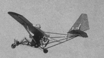
Dmitriev’s airplane is neither an outgrowth of a hang glider nor an enclosed cockpit design. First, it’s in-credibly tiny only 10.9 feet long, 16.4 feet in wingspan, and four feet high at the tail. Its wing area is only 18.9 square feet. It’s light, even by ultra¬light standards 110 pounds, as Dmitriev had it outfitted in July 1992.
But Dmitrievs diminutive craft is most striking in its use of big airplane features to get maximum performance from its flying surfaces. Its wing has airliner style flaps and leading edge slats, giving it more lift and thereby reducing takeoff and landing speeds. A slight but noticeable forward sweep to the wing makes it more controllable at low speeds. And extra joints in the elevators and rudder increase the effectiveness of their small surfaces.
It all comes apart and folds up for storage. Each wing section detaches and then folds in half, the tail group comes off and folds, and even the aluminum tubes connecting the tail section are designed to telescope. The result is a package you can store in a closet, rightfully earning it the nickname of “suitcase ultralight.”
The X 14d’s leading edge slat and triple slotted flaps are controlled by a single mechanical lever on the pilot’s left side, the flaps and slats extend and retract in unison. Fully extended, they greatly magnify the lift of the X 14d’s tiny wings and reduce the speed needed to get airborne. They also allow a slower landing. On the down side, flaps also increase drag, so they’re retracted into the wing structure for cruising.
Similar slotted surfaces are evident at the tail, but their functions are different. Horizontal elevators at the rear deflect the air passing over them, controlling the air¬plane’s pitch axis; Dmitriev added joints in the elevators to increase their effectiveness without increasing their size. The upright rudder, which controls yaw axis gets a similar segmented treatment.
Aiding the X 14d’s ailerons are spoilers, or short slats, that rise from the upper surface of the wing just forward of the ailerons. In Dmitriev’s design, each spoiler ex¬tends automatically when the aileron behind it is fully deflected, enhancing roll control.at low speed.
Primary flight functions, including throttle setting, elevator position, and aileron position, are con¬trolled from a hand hewn control yoke. Seated forward of the wing, With legs nearly straight ahead the pilot hss an unimpeded view, though his ears are just inches from the engine din.
Dmitriev is hardly a test pilot, and he said his longest flight in Kirghizia lasted just 8.5 minutes, when his engine quit. He says the highest he has flown it is 350 feet much too close to the cold, hard ground for testing a plane’s behavior in steep turns or stalls.

Engine: 24 hp.
Length: 10.9 ft.
Wingspan: 16.4 ft.
Height: 4 ft.
Wing area: 18.9 sq.ft.
Empty wt: 110 lbs.

Dixon Flying Car

Jess Dixon, of Andalusia, Alabama, got tired of being tied up in traffic jams, so he designed and built this novel flying vehicle around 1940. It was a combination of automobile, helicopter, autogiro, and motorcycle. It had two large lifting rotos in a single head, revolving in opposite directions. It was powered by an air-cooled 40 h.p. motor. He claimed his machine was capable of speeds up to 100 miles an hour, according to Modern Mechanics (Nov, 1941).