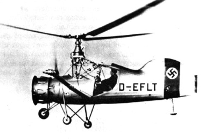
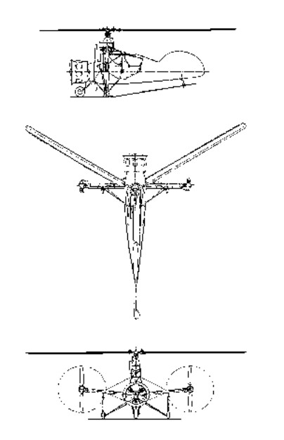
The development contract for the Fl 185 was issued by the RLM in February 1937; two SV-Types were planned. It was given the designation “Helicopter Conversion 184” in the Aircraft Development Program, because the planned Fl 184 V3 was used in the construction of the Fl 185 V1. The Fl 185 project was financed with the insurance sum received from the destroyed Fl 184 V1 and a grant of approximately RM 50,000 from the RLM. Mockup inspection took place in April 1937.
The Fl 185 was a gyroplane equipped with a three-blade rotor. Torque balance was achieved by means of variable-pitch pusher propellers driven by extension shafts located at the ends of outriggers mounted on each side of the fuselage. The starboard propeller produced backward thrust, the port forward, so that the total moment exerted on the fuselage balanced that of the main rotor. The centrally-mounted Sh.14A engine drove, in addition to the rotor and anti-torque propellers, a large cooling fan in the nose consuming about 14hp. The main gearbox was in the front part of the cockpit.
The sole prototype built was the Fl 184 V1 D-ELFT, which carried out a number of flights m 1938. The Fl.185, which had a three-wheeled undercarriage, was given only a few tests near the ground, and then abandoned in favour of the Fl.265, which embodied the intermeshing rotor system on which Flettner had now begun to work.
In December 1934 talks were held by the development group of the RLM (LC II) in the presence of State Secretary Milch which were to lead to important decisions concerning future air armaments.
The following is noted in the minutes under Section 4 “Rotary Wing Aircraft”: “The development of rotary wing aircraft is to receive preferential treatment. Consequently all work now under way is to be accelerated, as these aircraft will presumably be of significance for land and sea use in the future.”
In the LC II.1’s general working plan (Dec. 1935) “rotary wing aircraft” appeared under the heading: “Sport, basic training, advanced training and special aircraft” (Report II/1a). The following types are listed: Fi 184, Fw 61, Focke Wulf project (the later Fw 186) and LC 30 Focke-Wulf license.
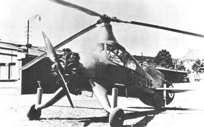
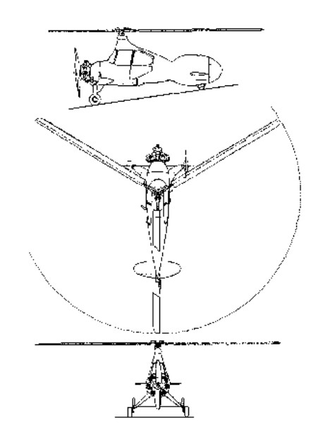
In January 1935 Flettner received a development contract from the RLM for an “experimental autogiro” (autogiro with three-blade rotor). Three so-called “SV-Types” were planned. Inspection of the mockup took place in June 1935. Only one prototype, the Fl 184 V1 D-EDVE was built. The aircraft was destroyed as a result of pilot error in the course of its maiden flight in December 1936. The Fl 184’s external shape still exhibited a certain similarity to the C 30 autogiro being built under license by Focke-Wulf at that time. Power was provided by an Sh 14 engine driving a conventional propeller.
The Fl 185 project was financed with the insurance sum received from the destroyed Fl 184 V1 and a grant of approximately RM 50,000 from the RLM.
The FL-23 prototype was designed and built as a private venture, it was a high-wing cantilever monoplane with an all-moving tailplane mounted at the top of the fin. It had a fixed tricycle landing gear and powered a 225-hp (168 kW) Continental E225 piston engine. It had room for a pilot and observer in tandem; the observer had an unusual acrylic plastic enclosure to give an all-round visibility.
The US Army issued the specification for a two-seat liaison and observation monoplane and the prototype was entered into the competition. During trials the aircraft was badly damaged in a flying accident when it lost its tail, and was withdrawn from the competition. The competition was won by the Cessna 305A which became the L-19 Bird Dog.
Powerplant: 1 × Continental E225, 235 hp (175 kW) Propeller: Hartzell 7 ft (2.1 m) diameter Wingspan: 33 ft 4 in (10.16 m) Length: 28 ft 4 in (8.64 m) Height: 8 ft 1 in (2.46 m) Wing area: 277 sq ft (25.7 m2) Airfoil: NACA 4412 Empty weight: 1,500 lb (680 kg) Gross weight: 2,450 lb (1,111 kg) Fuel capacity: 60 US gal (50 imp gal; 230 L) Maximum speed: 133 mph (214 km/h, 116 kn) Cruise speed: 118 mph (190 km/h, 103 kn) Stall speed: 38 mph (61 km/h, 33 kn) (flaps extended) Range: 485 mi (781 km, 421 nmi) Service ceiling: 19,500 ft (5,900 m) Rate of climb: 1,180 ft/min (6.0 m/s) Crew: 2
John Thorp was interested in armed light aircraft and in 1948 he demonstrated the prototype Sky Skooter at Fort Bragg. At the start of the Korean conflict Thorp sold his basic armed lightplane concept to Wendell and Maurice Fletcher. The result was the FD-25 series. Developed by the Fletcher brothers and John Thorp it was aimed at a perceived need in the US armed forces for a cheap and lightweight counter insurgency (COIN) attack aircraft.
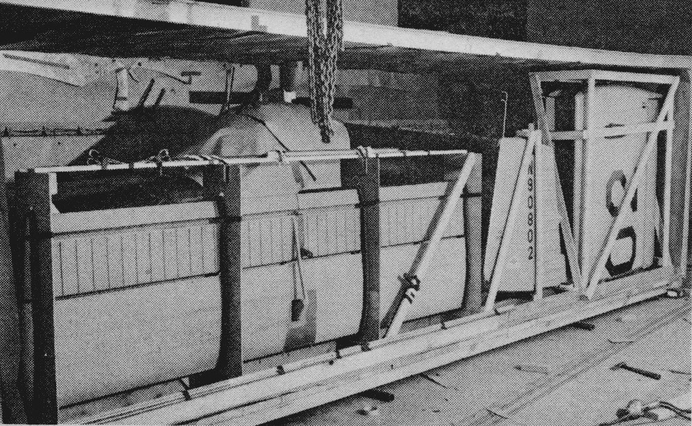
The prototype FD-25, N90802, received the green light from the Fletcher management on 1 November 1950. Five engineers, including Thorp, and five engineers were assigned to the project. The prototype flew on 14 April 1951. The single seat FD25 was manufactured from Dow magnesium rather than aluminium. According to Thorp was “economically marginal because of the extra processing, equivalent to anodising, that was required to resist corrosion”.
Prototype magnesium FD-25 Marine HQ, Quantico, Virginia. Pilot Roy Cusick.
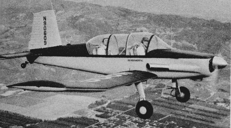
The FD-25A two-place version was begun before the single-place flew. The aircraft, N90609, had a magnesium wing and aluminium fuselage. Heavy navigation equipment resulted in a critical aft c-of-g condition that contributed to the FD25A crashing during flight trials in 1952, killing several Fletcher employees.
FD-25A – pilot Roy Cusick, engineer Leland Lord. Both were killed in the plane
It was the two-place version that was built in Japan.
Protype FD-25 crated for shipment to Toyo Aircraft in Tokyo, Japan
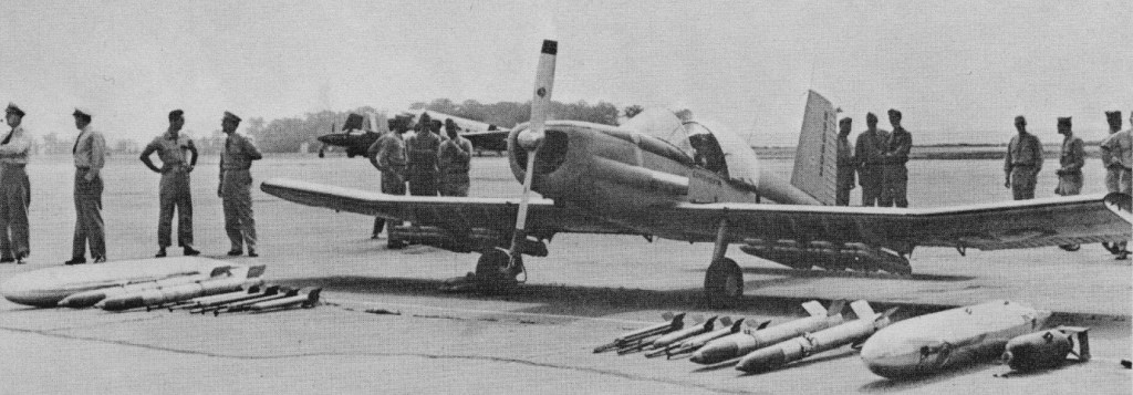
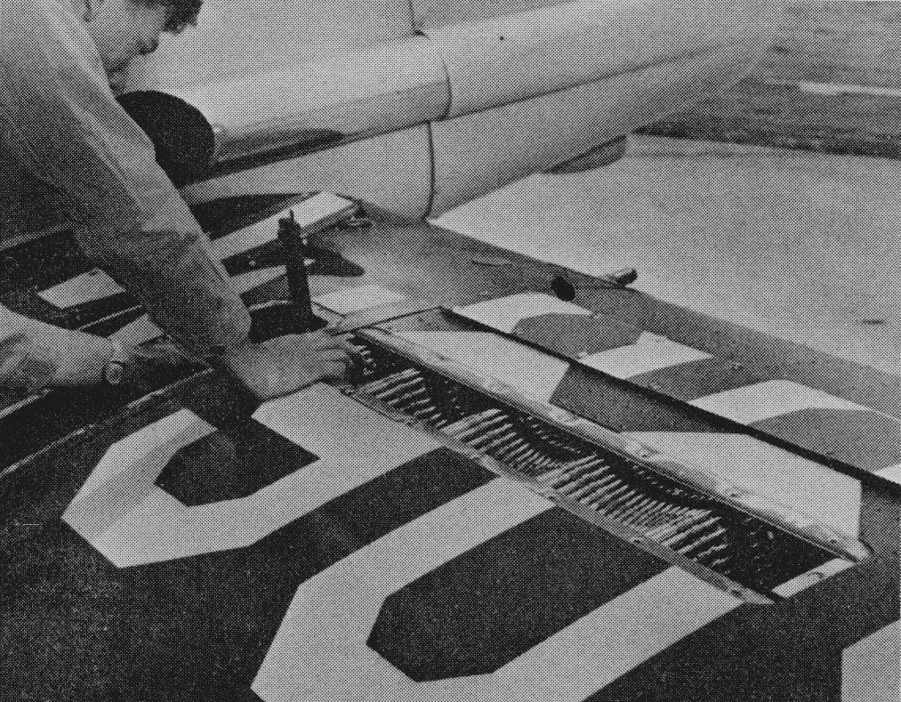
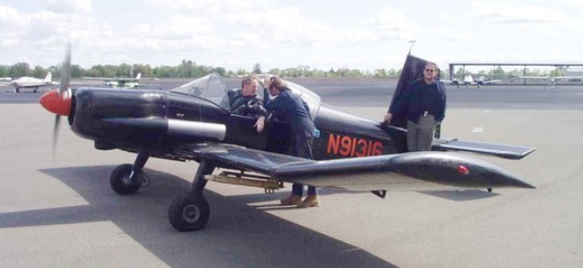
Fletcher then took nine months to complete the all-aluminium FD-25B N91316. Two 30-calibre machine guns were imbedded in the wings, mounted outboard of the fuel cells and firing outside the propeller arc procured on bailment from the office of Admiral Richardson, then Chief of Naval Aviation. Each gun had space for 1000 rounds of ammunition.
Thorp, who made the initial flights in all the FD-25s, also fired the first in-flight rockets on the range at Inyokern, California. In preliminary ground firing, the cap on the back of the 5-in HVAR rockets ejected with such force that it damaged the stabiliser. The rocket rails were then moved farther outboard.
The plane was to depend on surprise attack and was built without armour plate or self-sealing tanks. The FD-25 was created to stop Russian T-36 tanks used by the North Koreans.
The FD25B undertook very successful demonstrations with the US armed forces. The FD25B was a performer and was enthusiastically supported by US military personnel but unfortunately received no US Government support.
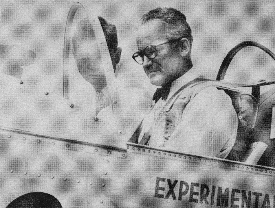
Senator Barry Goldwater flew the experimental FD-25B solo, as did Chuck Yeager.
Senator Barry Goldwater in the FD-25B, Washington-Virginia airport in 1953.
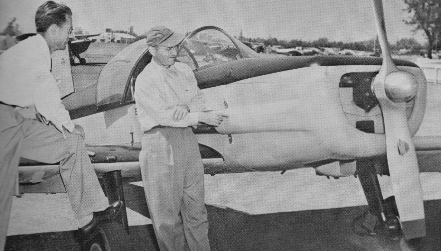
Circa 1951, John Thorp (right) and Don Downie with prototype FD-25. The fixed pitch propeller was later changed to a Hartzell controllable.
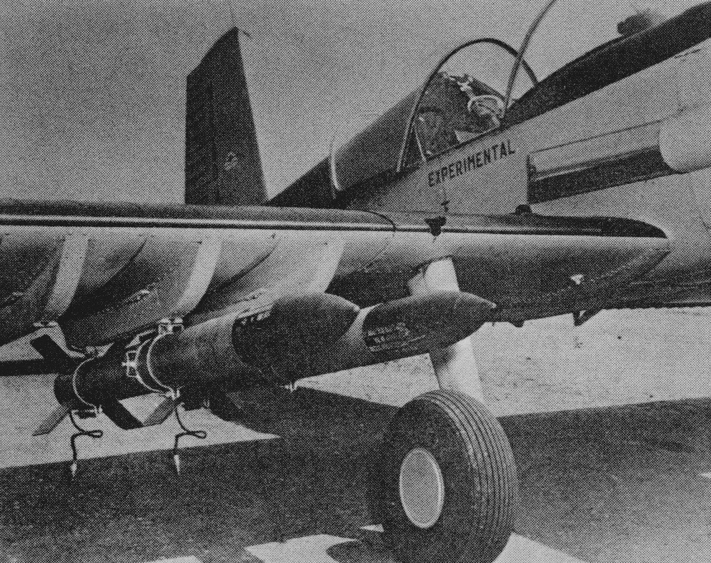
The FD25B armament consisted of a pair of wing mounted racks for two 33-gallon napalm tanks. Additionally two 250 lb. fragmentation bombs and up to 40 2.75 inch folding fin air rockets of four 5.0 inch heavy rockets or twenty 80 mm Oerliken rockets could be fitted.
Fletched ceased production after three examples to then concentrate on the development of the FU-24. However, further FD25 production was undertaken under license in Japan by the Toyo Aircraft company.
The first Toyo example, a FD25B, was flown in March, 1953 and soon after sales of four FD25A and four FD25B were made to the Royal Cambodian Air Force. These were followed by an unclear number, possibly two each FD25A and FD25B, to the North Vietnamese Air Force. The fate of these airframes is unknown.
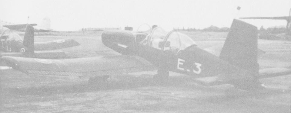
Cambodian Air Force FD-25
Much of the demonstration life of the FD-25B was flown with a full dull black paint job. The FD-25 was designed to sell originally for $25,000 or less.
Ex-WW2 fighter pilot Jim Castor took over the FD-25 project after Don Downie and obtained the only known 25 in existence. He obtained it from the company after it had collected dust for eight years and refurbished it in his garage in La Mirada, California. Part of Castor’s agreement with Fletcher Aviation was to demonstrate the airplane to any potential customer on request.
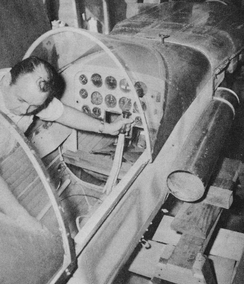
Jim Castor inspects the FD-25B prior to re-assembly
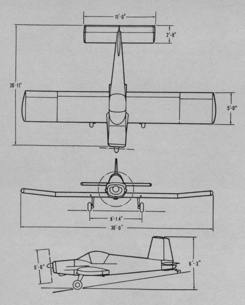
Engine: Continental E225-8, 225 hp. Wingspan: 30 ft Length: 20 ft 11 in Height: 6 ft 3 in Wing area: 150 sq.ft Empty weight: 1228 lb MTOW: 2500 lb Fuel capacity: 50 gal Max speed: 187 mph SL Cruise speed: 162 mph SL Service ceiling: 16,500 ft Range: 630 mi Armament: 2 x 0.30in mg Hardpoints for: 2 x 33 gal nalpalm, 2 x 250 lb bombs, 40 x 2.75in rockets, or 4 x 5in rockets
FD-25B Engine: Continental E225, 250 hp Propeller: Hartzell controllable pitch Wingspan: 30 ft Wing area: 150 sq.ft Airfoil: NACS 652-415 Aspect ratio: 6-1 Chord: 60 in Outer wing dihedral: 6 deg Length: 20 ft 11 in Height: 6 ft 3 in Gross weight: 2700 lb Empty weight: 1428 lb Useful load: 1272 lb Fuel capacity: 60 USG Max speed: 187 mph Cruise speed: 162 mph Landing speed: 45 mph ROC: 1725 fpm Service ceiling: 16,500 ft Cruise range: 630 mi Take-off distance: 500 ft Landing distance: 330 ft Fin area: 8 sq.ft Rudder area: 4 sq.ft Wlevator area: 9 sq.ft Stabiliser area: 21 sq.ft Seats: 1
Tomasz Fleger of Warsaw (who already designed in 1911 a floatplane and airship) designed and built a small monoplane pusher in 1914, which, however, never flew.
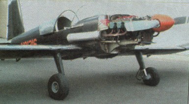
F-401 prototype, Golden Wings Museum, Blaine, Minnesota
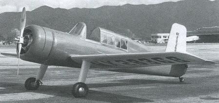
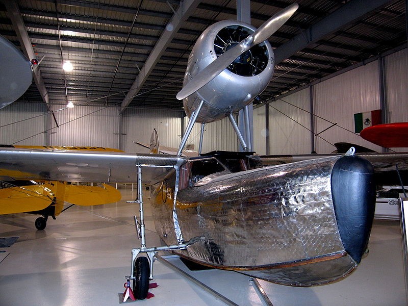
The Sea Bird was an amphibious utility aircraft designed in 1934–1935 by James C. Reddig for Fleetwings, Inc., of Bristol, Pennsylvania. While the aircraft’s basic configuration had a precedent in the design of the Loening “Monoduck” developed by the Grover Loening Aircraft Company as a personal aircraft for Mr. Loening (for whom Reddig worked from 1929 to 1933), the Sea Bird was unusual because of its construction from spot-welded stainless steel. It was a high-wing, wire-braced monoplane with its engine housed in a nacelle mounted above the wings on struts.
The pilot and passengers sat in a fully enclosed cabin.
First flying in 1936, Fleetwings initially planned to manufacture 50 production units, but at a price approaching $25,000 during the Depression, there proved to be no sustainable market and only five production F.5 Seabird were built.
The Sea Bird found use with private pilot owners and saw service with the oil support industry in Louisiana, including operation by J. Ray McDermott & Co.
Powerplant: 1 × Jacobs L-5, 285 hp (213 kW) Wingspan: 40 ft 6 in (12.34 m) Wing area: 235 sq ft (21.8 m2) Length: 31 ft 5 in (9.58 m) Height: 12 ft 6 in (3.81 m) Empty weight: 2,320 lb (1,052 kg) Gross weight: 3,450 lb (1,565 kg) Fuel capacity: 52 US gal (43 imp gal; 200 L) Maximum speed: 150 mph (240 km/h, 130 kn) at sea level Cruise speed: 133 mph (214 km/h, 116 kn) Range: 400 mi (640 km, 350 nmi) Service ceiling: 15,000 ft (4,600 m) Rate of climb: 900 ft/min (4.6 m/s) Crew: 1 Capacity: 3 passengers
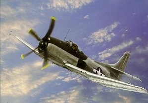
In early 1942 the U.S. Navy’s Bureau of Aeronautics (BuAer) was planning the replacements for the Curtiss SB2C Helldiver dive bomber and the Grumman TBM Avenger torpedo bomber. The aircraft was to carry the torpedo in an internal bomb bay. By late 1943 it became obvious that the proposed VBT design like the Douglas SB2D had drastically increased in size and weight. Therefore the U.S. Navy was initiating a smaller dive bomber design. The BuAer recognized the engineering workload for the major wartime programs and therefore assigned the design to companies without a major wartime production. BuAer selected Fleetwings at Bristol, Pennsylvania (USA), which was acquired by Henry J. Kaiser in 1943.
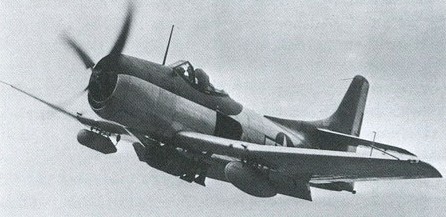
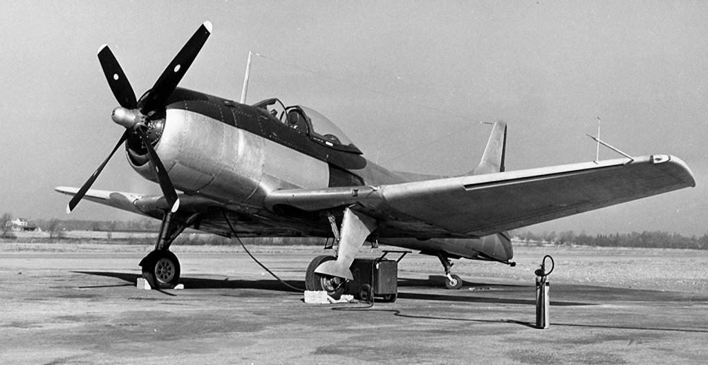
The XBK dive bomber program was initiated in February 1944 with a contract for two prototypes. To keep the airplane size down it was decided that all stores would be carried externally. A radar could be carried underneath the left wing. The dive brakes were of the lower and upper picket fence type at the inboard wing trailing edge. The horizontal tail was mounted on the tail fin above the fuselage. This feature should also avoid buffeting when the dive brakes were open. Unusual was the placement of the engine exhausts almost aft of the cockpit. It was hoped that this feature would significantly decrease drag.
A mockup inspection without engine was already in April 1944. The engine was installed in May 1944 and the completion of the first prototype was scheduled for November 1944. To speed up later production the U.S. Navy even constructed a new airfield at the Fleetwing plant. In early 1945 BuAer requested that the plane would be able to carry a torpedo. The weapon was fitted to a new centreline station and the designation was changed to BTK. The first XBTK-1 was finally completed in March 1945, making its first flight in May 1945.
The flight testing revealed an inadequate engine cooling and a major fuselage vibration. These problems were corrected up to July 1945, and the R-2800-22W engine, which was already out of production, was replaced by the -34W. The flight testing continued at the U.S. Navy Naval Air Test Center at Naval Air Station Patuxent River, Maryland (USA), in August 1945. After the end of the Second World War the U.S. Navy cut orders to ten planes. The major redesign the NATC recommended was the use of a standard engine exhaust, as the cockpit temperature was very high and cockpit egress and access after an engine shutdown was extremely difficult. Also a new propeller should be installed. The plane was transported back to Fleetwings where redesign began. The second production aircraft first flew in March 1946 and featured built-in leading edge slots which greatly increased the stall performance of the aircraft. However, by early 1946 procurement of new planes was drastically cut down and the BTK found its role already filled by the Douglas AD Skyraider and Martin AM Mauler. In May 1946 it was decided to delay corrections of the design and complete five airframes already in production. Although a promising design, the U.S. Navy finally terminated the contract on 3 September 1946, as there was no need for the aircraft anymore. The five prototypes were scrapped.