Grumman G-712 / Grumman X-29

Grumman Aerospace, Rockwell International and General Dynamics, proposed to DARPA that a for-ward swept wing demonstrator should be built. The demonstrator would be used to: verify that composites could provide the wing stiffness required without severe weight penalties; verify the aerodynamic advantages of a forward swept wing indicated in wind tunnel testing; and expand the forward swept wing technology base.
DARPA responded favourably and there followed three years of intensive competitive design studies, culminating in Grumman Aerospace being selected to build two demonstrators in 1981 under an $80 million contract, based on their Project Design G 712. This was officially designated X 29A by the U.S. Air Force in mid 1981.
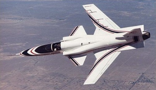
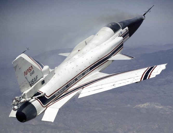
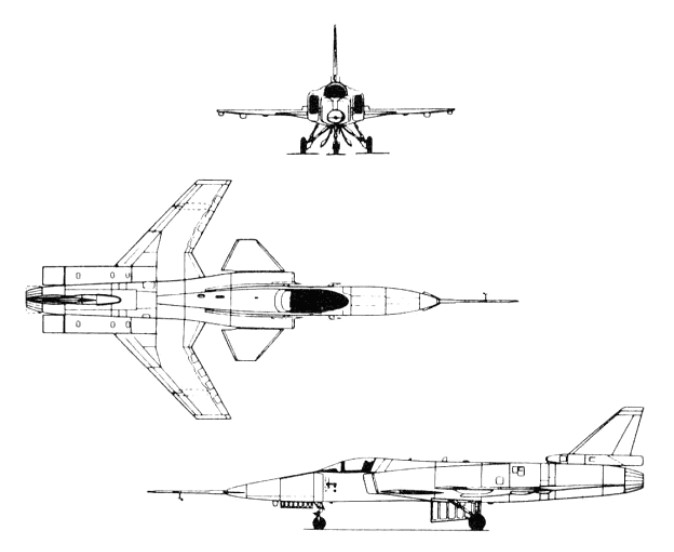
The X-29A was a single-seat jet aircraft fitted with a wing mounted at the rear of the fuselage, swept forward at 35 degrees, and having shoulder-mounted canards just behind the cockpit.
To save development time and money, Grumman used as many parts as practical from existing aircraft. The forward fuselage and nose landing gear are from a Northrop F 5A (the 15th built from the mid-1960s), and the main landing gear and control surface actuators are from a General Dynamics F 16A. Off the–shelf equipment includes the emergency power unit and the flight control servo actuators, also from an F 16A. The aircraft is powered by a single General Electric F404 after burning turbofan, developing 16,000 lb. thrust, and is the engine type used in the McDonnell Douglas F/A 18 Hornet.
The tapered variable incidence foreplane was selected after intensive wind tunnel testing and is used to provide pitch trim and control movements, as this type of surface provides lift for trim. It also acts as a slat to help the heavily loaded inboard section of the wing.
The X 29A is a highly unstable aircraft, the c.g. being no less than 35% aft of the aerodynamic centre of the wing/canard surfaces. Initially the planned instability was intended to be only 20%, and accordingly the canard had an area equal to 15% of the wing. Wind tunnel tests, however, showed that this would not give the degree of control required during transonic manoeuvres, and the canard size was increased to 20% of the wing, giving the current degree of instability.
The heart of the X 29A is its distinctive forward swept wing. It is a very thin wing; the thickness to-chord ratio being less than 5%. The wing area is 188 sq. ft. and the angle of forward sweep 30 deg.

Ultimately, the X-29 emerged with three digital channels so that any two could detect a failure in a third, plus a fourth, analogue backup channel which could control the aircraft over a limited flight envelope. The main role of the fourth channel was to protect the aircraft in case some unsuspected freak software mode disabled all three digital channels simultaneously.

The inboard end of the leading edge is swept aft, to alleviate some of the root stall problems associated with forward sweep. To preserve the structural integrity of the vital lower wing skin, the main landing gear retracts forward, into the fuselage ahead of the wing. The trailing edge of each wing root extends aft to form a large body strake ending in a controllable flap. The strakes add area behind the c.g. and hence improve directional stability.
It is on the outer, forward swept portion of the wing that the unique directional properties of carbon fibre laminates construction are used to overcome the adverse wing twist, or “divergence”, without the prohibitive weight penalty of a conventional aluminium alloy structure. A total of 752 plies is used, with 156 layers at the thickest section of the skin. To resist the natural tendency of the forward swept wing to twist, the layers are “rotated” some 10 deg. forward of the wing’s structural axis.
The laminated wing skins, at an angle to the bending axis, shear forward under compression and back¬ward under tension. The effect of shearing under load on the wing torsion box is to generate a nose down torque which counters the natural tendency of the wing to twist leading edge up. The carbon fibre skins are attached to a sub structure of conventional aluminium alloy construction, the front spar being of electron-beam welded titanium to cater for the high loads on the front part of the wing due to the forward sweep.
Full span “variable camber” flaperons are fitted to the wing trailing edge, these being used symmetrically for pitch control and asymmetrically for roll. The flaperons are in three sections, being hinged at two chord wise locations, so that they may be used to change the camber of the wing. The primary hinge is at 75% chord and the secondary hinge is at 90% of the chord. The flap sections are geared so that for every 1 deg. of flap deflection the aft section deflects an additional 1 deg. The flap increases manoeuvrability and reduces drag across the entire speed range. Programmed by the flight control computer, the flap alters the wing shape in flight as a function of changing conditions. The result is a constantly optimum wing shape.
The core of the wing structure is an electron-beam-welded box of titanium and light alloy, providing an exceptionally sturdy but generally conventional basis for the outer aerodynamic surfaces. The latter are single-piece upper and lower skins made of carbon fibre reinforced plastics up to 156 layers thick at the inboard ends. The skins are exceptionally light yet rigid, and can sustain violent manoeuvres without any possibility of aeroelastic divergence. The leading edges are fixed, with no provision for high-lift devices of any kind, but the trailing edges are fitted with full-span flaperons that can be used as camber-changing sections.
Located aft of the wing are the conventional rudder, plus a pair of strake flaps fitted at the extreme rear of the extended wing root trailing edges, nearly in line with the rudder. Powerful canard foreplanes with one-fifth of the wings’ area are located on the sides of the lateral inlets, and just forward of the inboard sections of the wing leading edge, which are conventionally swept back. The canards are driven through a triple-redundant fly-by-wire flight-control system, and are the aeroplane’s primary control surfaces in the pitching plane. The canards are used to trim out any tail up pitching moment by generating lift, augmenting the lift of the wing.
Flight tests have confirmed wind-tunnel predictions about the X-29’s flight characteristics: even at extreme high angles of attack the aircraft cannot be stalled and it retains full roll authority down to very low speeds. Early flight trials also indicated that fuel burn was lower than expected, an indication of extremely low drag.

The X 29A flew for the first time on 14th December 1984, from NASA’s Dryden Flight Research Facility at Edwards Air Force Base, California, with Grumman chief test pilot Chuck Sewell at the controls. For this first flight, which lasted 57 minutes, the landing gear and the variable camber trailing edge devices were kept down. The gear and flaps were retracted during the second flight on 4th February 1985. Two further flights were made on 25th February and 1st March. Two 360 deg. rolls were made during the third flight. After just these four flights the demonstrator was turned over to NASA in March 1985 for further flight testing.
In the initial phase of testing low altitude, high speed manoeuvres, the X 29 demonstrated high g turns tighter than anything achieved by a conventional fighter and displayed awesome potential for combat aircraft. For an extended test phase, the second aircraft was fitted with a vortex flow control system to test the possibility of using high pressure nitrogen injected directly into the vortices coming off the nose to help maintain control at high AoA. With this, pilots were able to achieve good control response to an AoA of 67 degrees.

The first aircraft (83-0003) flew on 14 December 1984, piloted by Charles Sewell, but was grounded on 6 December 1988 after its 242nd flight. The second X-29A (83-0049), flown for the first time on 23 May 1989, completed its flight test programme in October 1991. Between them the two aircraft completed 374 flights (more than any other X-craft) and demonstrated angles of attack up to 67 degrees (the target was 80). They also flew at Mach numbers up to 1.52 and reached altitudes up to 12200m. Both aircraft were now in store at the Ames-Dryden Flight Research Facility of NASA at Edwards AFB, California.

The X 29 tests ended in 1992 after 436 flights.
Gallery

X 29A
Engine: 1 x General Electric F404 GE 400 after burning turbofan, 69847 N / 16,000 lb. s.t.
Wing span: 27 ft. 2.5 in. / 8.3 m
Length: 16.4 m / 53 ft 10 in
Height: 14 ft. 3.5 in. / 4.4 m
Wing area: 17.5 sq.m / 188.37 sq ft
Foreplane area: 35.96 sq.ft.
Empty wt: 13,800 lb. / 6260.0 kg
MTOW: 17,800 lb. / 8074.0 kg
Max. payload weight : 12819.9 lb / 5814.0 kg
Max speed: Mach 1.6 approx.
Ceiling: 15300 m / 50200 ft
Crew: 1
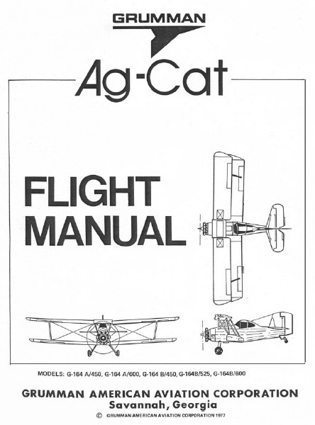
Grumman G-164 Ag-Cat / Agro Aircraft Eshet

Ag-Cat B

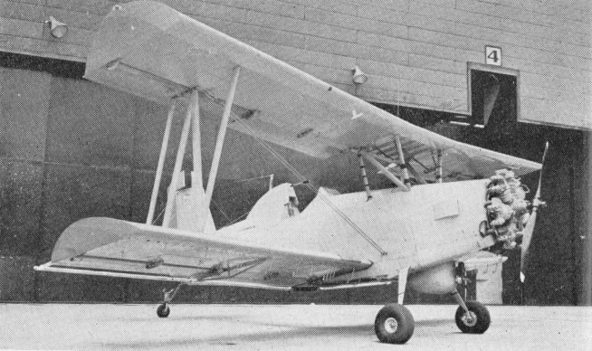
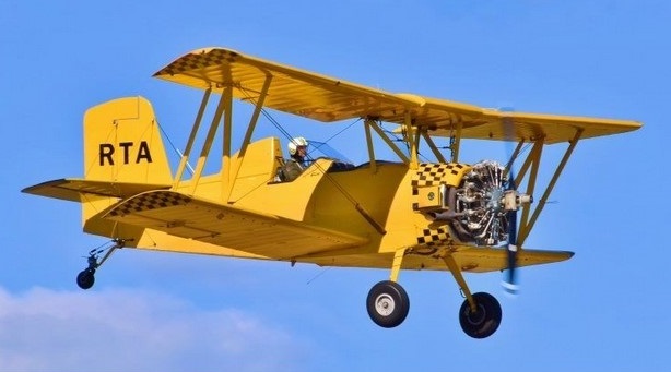
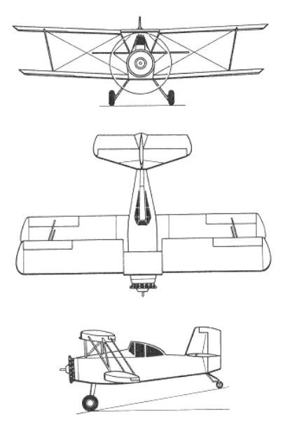
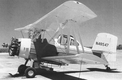
The Grumman Aircraft Corporation designed the G-164 Ag-Cat in the middle of the l950s but only built two aircraft, the first, N74054 (#X1) being flown on 27 May 1957, as later that year Grumman contracted the Schweizer Aircraft Corporation of Elmira, in New York State, to build 100 aircraft. The first of these, N10200, was flown on 17 October 1958 and the Grumman G-164 Ag-Cat was certified by the FAA in the restricted category in January 1959. The engine for the prototypes and early production aircraft was the Continental W670-6N seven-cylinder radial of 220 hp. Because of its lighter weight than other engines, the longer engine mounts were cowled and gave the Ag-Cat a length of 24 feet and six inches. The wing-span was 35 ft8 in.
The first twenty-odd aircraft had flat fuselage side panels, rather than the more familiar ribbed panels. These early model aircraft were fitted with 215 US gallon hoppers.

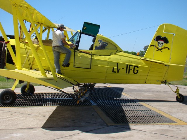
The G-l 64 was also certified for the 220-225 hp Gulf Coast W670-240 (a modified Continental tank engine) and the 245 hp L4M or L4MB, 275-300 hp Jacobs R-755. Once with operators, some aircraft were converted to the 450 hp Pratt & Whitney R-985 or the 600 hp R-1340, the latter readily recognised by extremely short engine mounts. Aircraft in the serial range 301-400 were built new with a 300 hp Jacobs R755 and an aluminium hopper of 245 US gallons installed. Nearly all of these aircraft were fitted with an enclosed canopy, which were also retrofitted to earlier aircraft.
Production of the G-164A Super Ag-Cat, with the P&W R-985 and a 300 US gallon fibreglass hopper, began in 1966 with number 401, N895X. The R-1340 engine was also fitted to these aircraft. Production of the G-164A ended at number 1730 with N6894Q.

In 1974 Grumman American announced a new model Ag-Cat. The wingspan had been increased from 36 feet to 42 feet 3 inches, but the hopper size remained at 300 US gallons and the new model was introduced with the 450 hp R-985 and, again, the R-1340 was later fitted. The recognition feature of the G-164B was the broad cord fin and rudder. With the R-985 installed the length of the G-164B is 25 feet, 7 inches. N88348 (#1B) was the first G-164B completed and over 800 were manufactured before production ended. The G 164B was certified under the A model banner.
In 1976 a stretched version, the G-164C, was flown and put into production. This was followed by the many turbine conversions.
Grumman American introduced in 1978 the Ag Cat C duster, powered by a 600 hp Pratt & Whitney radial. It carries a 500 galIon hopper the biggest dustbin available in any production agplane. In February 1976 the Super Ag-Cat C was flown, and in November 1977 was certificated; it has a deeper and longer fuselage accommodating a 500 US gallon hopper.

The factory PT6 turbine conversion kit weighing in some 230 kgs lighter, is around 10 to 12 knots faster and the PT6 power will enable a full load of 1500 litres to be carried for most operations. Fitted will be a three bladed Harztell prop, providing for a quieter operation and a reversing capability if ever required.
Although the Grumman Aircraft Engineering Company designed the Ag-Cat, built the two prototypes and marketed the type (subsequently through its subsidiary Grumman American Aviation Company), Schweizer Aircraft Corporation manufactured all the production Ag-Cats. Schweizer built 1400 aircraft between 1959 and 1975 and, with the exception of the engine fitted, the appearance of Grumman’s Ag-Cat hardly changed. In 1978 Gulfstream American bought Grumman American, and in 1979 a dual trainer Ag-Cat was shown at the Paris Air Show, although this was apparently designed and manufactured by some other company.

By 1979 Schweizer had produced 2,455 Ag-Cats at its Elmira, New York factory: 1,730 G-164As, 659 G-164Bs, 44 G-164Cs, and 22 G-164Ds – Super Ag-Cat Cs with a PT6A turbo-prop.

Reported in March 1979 was the Gulfstream American Ag-Cat B fitted, by Page Industries, with a 600 shp Lycoming LTP 101 turboprop. First flight of the prototype was made on 22 November 1978 and the installation was notable for being 34 in / 86.4cm shorter than the PT6 in the Ag-Cat. Another installation in an Ag-Cat, flight tested late 1978, was a 650 hp liquid-cooed Vee engine developed by Stage II from the Chrysler “hemi-head” auto engine and offering less drag than the Ag-Cat’s usual radial. Mid-Continent of Hayli, Missouri fitted a 1200 hp Wright Cyclone R-1820 in an Ag-Cat to produce the King Cat, which will take off at its 9500 lb / 4313 kg gross weight from a 1000 ft / 305 m strip.

In 1981 Schweizer bought the Ag-Cat manufacturing and marketing rights from Gulfstream American, and produced an improved G-164B known as the Ag-Cat B-Plus and powered by either a 450-hp R-985 or a 600-hp R-1340 Pratt & Whitney nine-cylinder radial.

A Hershy FatCat modification widens the fuselage and raises the top wing some 8 inches.
Some have been powered by a Walter 601-F-II turbine engine delivering 750 hp using a five-bladed propeller, or the 600 hp Polish PZL 3S radial, and at least one has been equipped with two Lycoming TIO-540s, in separate Piper Seneca cowlings, mounted side-by-side, in the nose.

Ethiopian Airlines sc Company’s Agro Aircraft Manufacturing division produced the Ag-Cat Corporation Ag-Cat G164B Turbine under the name Eshet for distribution and operation in Ethiopia and African countries except Algeria, South Africa, and Tunisia.
Admas Air Service in Ethiopia has produced over 10 Grumman Ag-Cats under licence from Schweitzer.

Courtesy Jorge

Development: Frakes Turbo Cat

Gallery

G-164 Ag-Cat
Engine: Jacobs, 300 hp.
Useful load: 1800 lbs.

G-164A Ag-Cat
Engines: P&W R-985, 450 hp.
Seats: 1.
Wing loading: 18.52 lb/sq.ft.
Pwr loading: 13.5 lb/hp.
Max TO wt: 6075 lb.
Empty wt: 2870 lb.
Equipped useful load: 3168 lb.
Payload max fuel: 2688 lb.
Range max fuel/ 75% pwr: 244 nm/ 2.8 hr.
Service ceiling: 13,000 ft.
Hopper cap: 300 USG.
75% cruise: 89 kt.
Working speed: 89 kt.
Working endurance: 3.4 hr.
Stall: 68 kt. ROC: 400 fpm.
Min field length: 2320 ft.
Fuel cap: 276/480 lb.

G-164A Super Ag-Cat
Engine; 600-hp Pratt & Whitney R-1340 nine-cylinder radial.
Wing span; 35 ft 11 in.
Wing chord (constant); 4 ft 10 in.
Length; 24 ft 3in.
Height; l0 ft 9 in.
Wing area; 328 sq ft.
Empty, equipped; 3,159 lb.
Certificated max T-O; 4,500 lb.
Max TO wt: 6075 lb.
Power loading; 7.5 lb/hp.
Equipped useful load: 2893 lb.
Payload max fuel: 2413 lb.
Range max fuel/ 75% pwr: 171 nm/ 1.8 hr.
Service ceiling: 16,000 ft.
Hopper capacity; 33 or 40 cu ft.
Fuel capacity; 46, 69 or 80 US galls.
Never-exceed speed; 128 kt.
75% cruise: 98 kt.
Abrupt manoeuvre speed; 102 kt.
Working speed; 82-91 kt.
Working endurance: 2.9 hr.
Stall speed, power off; 59 kt.
Stall clean: 69 kt.
Rate of climb; 710 ft/min.
Take-off run; 395 ft.
Seats: 1.
Wing loading: 18.52 lb/sq.ft.
Fuel cap: 276/480 lb.

G 164B
Engines: P&W R-985, 450 hp.
Seats: 1.
Wing loading: 15.5 lb/sq.ft.
Pwr loading: 13.5 lb/hp.
Max TO wt: 6075 lb.
Empty wt: 3025 lb.
Equipped useful load: 3023 lb.
Payload max fuel: 2543 lb.
Range max fuel/ 75% pwr: 283 nm/ 2.8 hr.
Service ceiling: 14,000 ft.
Hopper cap: 300 USG.
75% cruise: 103 kt.
Working speed: 91 kt.
Working endurance: 3 hr.
Stall: 61 kt.
ROC: 625 fpm.
Min field length: 1820 ft.
Fuel cap: 276/480 lb.

G-164B
Engine: P&W R-1340, 600 hp.

Schweizer Super Ag-Cat 164B/600
Engine: P&W R-1340, 600 hp.
TBO: 1200 hrs.
Prop: Hamilton Standard 2-blade, 108-in.
Seats: 1.
Length: 25.9 ft.
Height: 11.3 ft.
Wingspan: 42.3 ft.
Wing area: 392 sq.ft.
Wing aspect ratio: 5.49.
Maximum ramp weight: 6075 lbs.
Maximum takeoff weight: 6075 lbs.
Standard empty weight: 3255 lbs.
Maximum useful load: 2820 lbs.
Maximum landing weight: 6075 lbs.
Wing loading: 15.5 lbs/sq.ft.
Power loading: 10.1 lbs/hp.
Maximum usable fuel: 480 lbs.
Hopper capacity: 400 USG.
Best rate of climb: 576 fpm.
ROC @ 6000ft: 379 fpm.
Service ceiling: 17,000 ft.
Maximum speed: 128 kts.
Working speed: 100 kts.
Fuel flow @ working speed: 192 pph.
Endurance at working speed: 2.4 hrs:
Stalling speed clean: 50 kts.
Stalling speed flaps down: 52 kts.
Turbulent-air penetration speed: 102 kts.
Fixed tail wheel undercarriage.

Grumman G-98 F11F Tiger / F-11

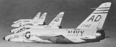
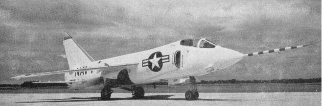
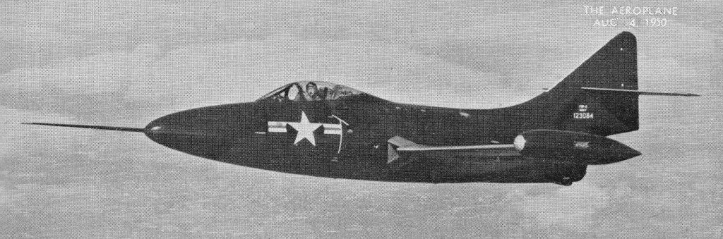
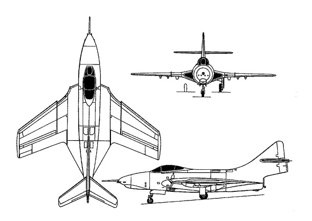
The US Navy’s first transonic shipboard warplane, development of the G-98 was ordered on 27 April 1953 as a revised and improved F9F-6. In the event, there was no commonality with the earlier fighter, but nevertheless, when the first example was flown on 30 July 1954, it was designated YF9F-9, this being changed to F11F-1 in April 1955.

Grumman F11F Tiger Article

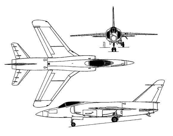
The airframe had mid-set wings sweptback at 30 degrees. There are swept-back tail surfaces, with an all-moving tailplane mid-set on the fuselage. No ailerons are fitted. Lateral control being by spoilers. Leading edge slats are fitted. Trailing-edge flaps are over the full span except for the folding tip portions. Finger type air-brakes are under the fuselage. Two underwing jettisonable fuel tanks may be fitted.

The tricycle under-carriage has a single wheel on each main unit and twin-wheel nose unit. The main wheels retract forward and into the fuselage, and the nose wheels retract rearward.

Able to fly supersonic in level flight, the F11F-9 Tiger was in production for the U.S. Navy in 1955. Six prototypes and 39 F9F-9 were ordered initially. Difficulties with the intended afterburning Wright J65-W-6 engine dictated installation of the derated J65-W-18 in the production F11F-1 with a maximum military thrust of 7,450 lb (3379 kg) and 10,500 lb (4 763 kg) with full reheat. In consequence, the F11F-1 failed to meet contractual performance guarantees.

F11F-1 Tiger

A small number of pre-production aircraft, each with a Wright J65-W-6 turbojet engine with afterburner, were followed by 39 production aircraft (ordered with J65-W-4 afterburning engines).

Grumman F11F-1

The last two Tigers of the initial production batch were fitted with the General Electric YJ79-GE-7 turbojet rated at 9,600 lb (4 355 kg) military thrust and 15,000 lb (6 804 kg) with reheat as F11F-1Fs.
One of the F11F-1Fs attained a speed of 1,963km/h and set a short-lived height record on 18 April 1958 of 23,449m.

A further contract for J65-W-18-engined Tigers placed for the US Navy brought the total number of F11F-1s built to 201, but these were gradually phased out of first-line service from 1959. Those which remained in second-line service when the tri-service designations became rationalised in 1962 were redesignated F-11A.

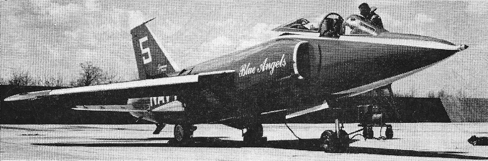
F-11A Tigers of Blue Angels 1965

Production was limited to 201 aeroplanes, the last being delivered in March 1957, service phase-out commencing in 1959.

F11F-9 Tiger

Gallery

F11F-1
Engine: 1 x Wright J-65-W-6, 33.8kN
Max speed, 753 mph (1212 km/h) at sea level.
Initial climb, 16,300 ft/min (82,8 m/sec).
Range, 1,108 mls (1783 km).
Service ceiling: 16700 m / 54800 ft
Empty weight, 13,307 lb (6 036 kg).
Max loaded weight, 23,459 lb (10 641 kg).
Span, 31 ft 8 in (9,65 m).
Length, 44 ft 10.75 in (13,68 m).
Height, 13 ft 2.75 in (4,03 m).
Wing area, 250 sq ft (23,22 sq.m).
Armament: four 20-mm cannon.
Crew: 1

F11F-1
Engine: 1 x Wright J-65-W-18, 10,500 lb
Span, 31 ft 8 in (9,65 m).
Wing area, 250 sq ft (23,22 sq.m).
Length, 44 ft 10.75 in (13,68 m).
Height, 13 ft 2.75 in (4,03 m).
Empty weight, 13,307 lb (6 036 kg).
Max loaded weight, 24,078 lb
Max speed, 740 mph / M1.12 at 35,000 ft
Service ceiling: 50,500 ft
Range, 600 mls
Armament: four 20-mm cannon.
Hardpoints: 4
Crew: 1

F11F-9 Tiger
Naval fighter
Crew: 1
Engine: Wright J65-W-7 Sapphire turbojet, with afterburner, 7500 lb. thrust.
Wingspan: 31 ft. 5 in
Length: 39 ft.
Loaded weight: approx. 14,000 lb.

Grumman G-93 F9F Panther / Cougar / G-99

F9F Cougar

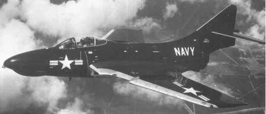
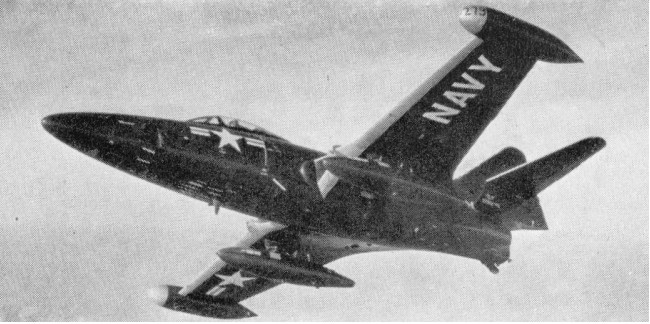
The first jet-powered ‘cat’ to be produced by Grumman and the first carrier borne jet to get into combat, the F9F Panther performed Korea where it constituted the backbone of US Navy and US Marine Corps air power, and by the time production ceased in late 1952 close to 1,400 had been built.

The Cougar was a swept-wing development of the earlier G-79 Panther. The fuselage was similar but the wings and tailplane were swept at 35 deg. The original layout of this single-seat carrier-based fighter provided for the installation of four wing-mounted Westinghouse 19XB-2B (Navy J30) axial-flow jets. But this arrangement was abandoned in favour of one fuselage-mounted high-powered turbojet engine before prototype construction began, a change prompted by the successful tests conducted by the Navy in December 1946 with two imported Rolls-Royce Nene engines. Grumman then turned its attentions to a single-seat single engine jet day fighter, two prototypes duly being ordered with the designation XF9F-2. Powered by an imported Rolls-Royce Nene engine, the first of these made its maiden flight on 24 November 1947 and such was the promise shown that substantial orders were soon forth¬coming for production-configured F9F-2 aircraft fitted with the licence-built Pratt & Whitney J42 copy of the Nene turbojet and British made Stanley Model 22G ejection seat.

The second prototype was similarly fitted, but the third (the XF9F-3) had an Allison J33 engine. Production aircraft were divided between Nene and Allison-powered models, the former engines licence-built by Pratt & Whitney as J42s.

The first production F9F-2, powered by a 22.24kN J42-P-6, flew for the first time on 24 November 1948. The 20.46kN J33-A-8-powered prototype flew for the first time on 15 August 1948 and a total of 418 of both versions were built. However the F9F-2 proved to be the better version and the F9F-3s were re-engined to F9F-2 standard.

Although the F9F-2 was the initial production model, the honour of being the first variant to enter service fell to the F9F-3, which used the slightly less powerful Allison J33 engine. This joined US Navy Fighter Squadron VF-51 during May 1949 but in the event only 54 F9F-3s were completed, most being modified later to F9F-2 standard. The next version to appear was the F9F-4 (73 of which were ordered originally) with the Allison J33-A-16, but none was completed and the contracts were combined with those for more than 580 27.80kN Pratt & Whitney J48-P-4/6A-engined F9F-5s (which flew for the first time on 21 December 1949). The F9F-2, -3, -4 and -5 were in service in 1955.

The most prolific variant was the F9F-5 which was powered by the Pratt & Whitney J48, a licence-built Rolls-Royce Tay, and redesigned fin and rudder. Over 600 were completed by the time production ceased at the end of 1952, this total including a small number of F9F-5P aircraft for photo reconnaissance duties. F9F-5P is long-nosed photo-reconnaissance version. Later machines can be seen with flight refuelling nose-probe.

F9F-5 Panther

The F9F-5 was the last version to see squadron service, being finally retired by VAH-7 in October 1958, although many Panthers continued to fly after that date with training units, and as F9F-5KD (from 1962 DF-9E) drone targets and controllers for missile trials.
The F9F-4 was powered by an Allison J33-A-16 engine. The F9F-5P was a photographic-reconnaissance version with a longer camera nose.

First flown in prototype form as the XF9F-6 on 20 September 1951, the Grumman F9F Cougar evolved from the earlier F9F Panther series of fighter aircraft. It differed mainly from its predecessors by virtue of posses¬sing swept wings and tailplane, thus earning the distinction of being the first swept-wing carrierborne type to enter service. Apart from this, changes were kept to a minimum to facilitate rapid production. Indeed, the new Cougar entered service just 14 months after its maiden flight took place, initial exam¬ples of the 32.25kN Pratt & Whitney J48-P-8-engined F9F-6 (later designated F-9F) joining VF-32 of the Atlantic Fleet naval air force during November 1951.

F9F-5 Cougar

Shortly after this, deliveries to Pacific Fleet units got under way, and the type was very soon introduced to combat in Korea. Production of the F9F-6 totalled 706 aircraft, 60 of which were completed as unarmed F9F-6P machines for reconnaiss¬ance duties with a longer nose to accommodate K-17 and tri-metrogon cameras, and these were followed by the F9F-7 (F-9H) which was pow¬ered by an Allison J33-A-16A turbojet. This proved to be only a temporary change, and after completing 168 F9F-7s Grum¬man reverted to the Pratt & Whitney J48 engine for the F9F-8 (which bore the Grumman design designation G-99) (F-9J), which became the definitive Cougar, well over 1,000 being completed in three basic variants. First to appear was the F9F-8 (601 built). Movable leading-edge slats were replaced by fixed cambered leading-edge extensions outboard of the wing fences. Total internal fuel capacity was increased by 530 litres. Large numbers were later modified to F9F-8B (AF-9J) standard with provision for air-to-surface guided missiles. The first production F9F-8 flew on 18 January 1954.

Grumman F9F Cougar / Panther Article

Some 110 of a photo-reconnaissance version designated F9F-8P (RF-9J) flew for the first time on 21 August 1955 and had an extended nose for the cameras.

F9F-5P

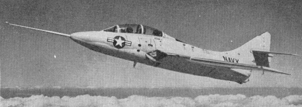
The Cougar also lent itself to the training of future naval aviators; a prototype two-seat YF9F-8T first flown on 4 April 1956 was followed by 399 F9F-8T (TF-9J) production examples, some of which remained in use with Naval Air Training Command until well into the 1970s. The F8F-8T was armed with two 20mm cannon and was 23 inch longer than the original cougar. Production of this version ended on the last day of 1959.

As far as front-line units were concerned, the Cougar disappeared from the scene early in 1960, the last operational version being the F9F-8P, but many continued to fly long after that date with the Reserve Force and with Air Training Command. Surplus aircraft became F9F-6K (QF-9F) and F9F-6K2 (QF-9G) target drones or F9F-6D (DF-9F) drone directors.

F9F-8T Cougar

Panthers are remembered for recording a victory against an enemy jet aircraft, a MiG-15, on 9 November 1950.

Replica: Gros F9F Panther

Gallery

F9F-5 Panther
Engine: one 3175-kg (7,000-lb) thrust Pratt & Whitney 148-P-6A turbojet
Maximum speed 932 km/h (579 mph) at 1525 m (5,000 ft)
Cruise speed: 774 km/h / 481 mph
Service ceiling 13380 m (43,900 ft)
Range 2092 km (1,300 miles)
Empty weight 4603 kg (10,147 lb)
Maximum take-off 8492 kg (18,721 lb)
Wingspan 11.58 m (38 ft 0 in)
Length 11.58 m(38 ft 0 in)
Height 3.73 m (12 ft 3 in)
Wing area 23.23 sq.m (250 sq ft).
Armament: four 20-mm cannon, plus up to 1361 kg (3,000 lb) of external ordnance.
Crew: 1
F9F-5 Cougar
Naval fighter
Engine: Pratt & Whitney J48-P-8 turbojet with afterburner, 7200 lb. thrust
Wingspan: 36 ft. 5 in
Length: 42 ft. 3 in
Loaded weight: approx. 20,000 lb.
Max. speed: 690 m.p.h.
Ceiling. 50,000 ft.
Range: approx. 1,000 miles.
Crew: 1
Armament: 4×20 mm. Cannon

F9F-5P
Naval photo-reconnaissance aircraft
Engine: Pratt & Whitney 148-P-6A turbojet, 6,250 lb. thrust
Wingspan: 38 ft
Max. speed: 625 m.p.h.
Loaded weight: 15,750 lb.
Ceiling: over 50,000 ft.
Max. range: 1,200 miles.
Crew: 1.
Armament: None

F9F-6
Engine: Pratt & Whitney J48-P-6A, 6,250 lb (2 835 kg).

F9F-7
Engine: Allison J33-A-16, 6,250 lb (2 835 kg).

F9F-8 Cougar
Engine: one 3289-kg (7, 250-lb) thrust Pratt & Whitney J48-P-8A turbojet.
Maximum speed 1033 km/h (642 mph) at sea level
Service ceiling 12800 m (42,000 ft)
Range 1690 km(l,050 miles)
Empty weight 5382 kg (11,866 lb)
Maximum take-off 11232 kg (24,763 lb)
Wingspan 10.52 m (34 ft 6 in)
Length 12.73 m(41 ft 9 in)
Height 3.72 m (12 ft 2.5 in)
Wing area 31.31 sq.m (337 sq.ft).
Armament: four 20-mm cannon, plus up to 1814 kg (4,000 lb) external ordnance

F9F-8P

TF-9J
Engine: 1 x Pratt & Whitney J48-P-8A turbojet, 32.0kN
Max take-off weight: 9344 kg / 20600 lb
Wingspan: 10.52 m / 34 ft 6 in
Length: 13.54 m / 44 ft 5 in
Height: 3.73 m / 12 ft 3 in
Service ceiling: 15240 m / 50000 ft
Range: 966 km / 600 miles
Armament: 2 x 20mm cannon, 907kg external

Grumman F9F Panther
Grumman F9F Cougar

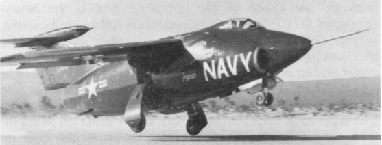
Grumman G-83 / XF10F Jaguar

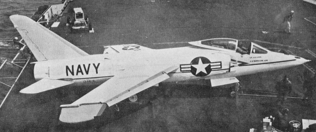
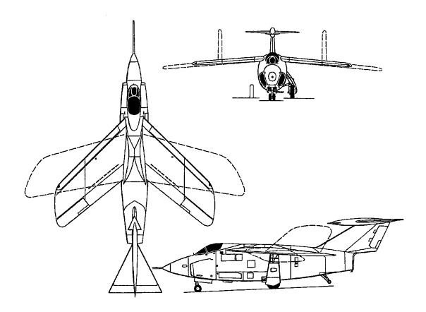
Greater success attended the development of variable-geometry wings, which allow the use of a minimum-sweep position for take-off and landing, an intermediate-sweep position for fuel-economical cruise, and a maximum-sweep position for high dash performance. The navy’s first essay in this field was the Grumman XF10F Jaguar, which was conceived in 1948 as a possible successor to the F9F Panther. The aerodynamic features of a variable-geometry type had already been explored in a number of aircraft, most notably the Westland Pterodactyl IV developed in the UK during the early 1930s, the Messerschmitt P.1011 designed in Germany during World War II, and the experimental Bell X-5 sponsored by NACA and the LTSAF with the ultimate purpose of validating a fighter-type wing with sweep variable between 20 deg and 60 deg. The X-5 had not flown when Grumman set to work on the Jaguar, but a considerable quantity of engineering data was available and this proved valuable to the Grumman engineers, who were faced with a host of problems.
Originally the XF10F had been planned as a development of the Panther with clipped delta flying surfaces. Designed as a transonic single-seat shipboard fighter with an internal armament of four 20-mm cannon and provision for an external bomb load of up to 4,000 lb (1814 kg). The sweep angle of the wings could be varied hydraulically between 13.5 and 42.5 deg, and high-lift devices consisted of full-span slats and an 80 per cent Fowler flap. The concept was then refined to the point at which a tilting variable-incidence wing was in adopted for reduction of the take-off and landing speeds. The navy then added additional responsibilities to the basic fighter-role, and these so increased the structure weight that the company came up with the notion of providing a variable-geometry wing. Further refinement was added after this when it was decided to allow the wing to be swept at any angle between the minimum- and maximum-sweep angles. The provision of such wings increased the type’s weight by 2200 lb (998 kg) but reduced landing speed from 132.5 mph (213 km/h) to 109 mph (175 km/h). The Jaguar was also provided with an advanced control system that included a delta surface forward of the fin to act as a servo for the all-moving tailplane and so improve control response at transonic speed.
The tailplane was operated by a novel arrangement where the pilot controlled a small delta-wing airfoil at the tip of the tail bullet. This in turn moved the main elevator Unfortunately, a lag in the response between stick and surface usually resulted in a Pilot Induced Oscillation (PIO) and the Jaguar was virtually uncontrollable much of the time.

The engineering of so complex an aeroplane took considerably longer than expected, and it was May 1953 before the XF10F prototype flew, three years behind schedule. The Jaguar was intended to be powered by a Westinghouse XJ40-WE-8 turbojet rated at 7,400 lb (3 357 kg) military thrust and 10,900 lb (4 944 kg) with full reheat, but when flight trials were initiated on 19 May 1952, a J40-WE-6 rated at 6,800 lb (3 084 kg) was fitted. The novel servo-control system for the tailplane proved far too slow in operation, and was replaced by a conventional powered tailplane, but it soon became clear that considerable revision of the basic design would have to be undertaken before production aircraft could be considered. Numerous problems arose during the test programme and as some of these could not be resolved, trials terminated with the 32nd flight on 25 April 1953. Orders had been placed for 112 production F10F-1s, but 100 of these were cancelled on 1 April 1953 and the remaining 12 on the following 12 June.
Empty weight, 20,426 lb (9 265kg).
Max loaded weight, 35,450 lb (16080 kg).
Span (min sweep), 50 ft 7 in (15,42 m), (max sweep), 36 ft 8 in (11, 17 m).
Length, 54 ft 5 in (16,59 m).
Height, 16 ft 3 in (4,95 m).
Wing area (min sweep), 467 sq ft (43,38sq.m), (max sweep), 450 sq ft (41,81sq.m).
Max. speed: 1143 km/h / 710 mph
Range: 2687 km / 1670 miles

Grumman TBF / TBM Avenger

TBM-3E

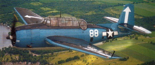
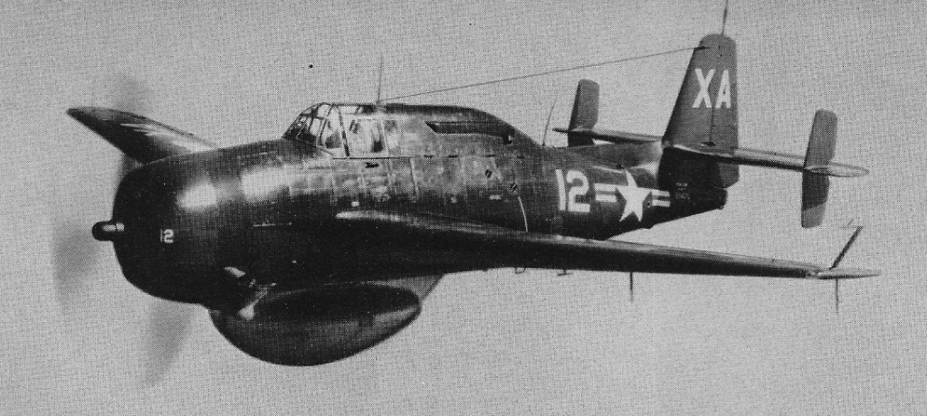
Two prototypes designated XTBF-1 were ordered on 8 April 1940, the first flying on 1 August 1941. The engine was a Wright R-2600-8 Cyclone 14-cylinder two-row radial rated at 1700 hp driving a Hamilton Hydromatic propellor. The extremely large wings folded to the rear about skewed hinges so that they lay along the sides of the fuselage, upper surfaces outwards. The main landing gear had a wide track yet retracted outwards into the wings. The fuselage accommodated a crew of three and an internal weapons bay, and the defensive and offensive armament was well planned. The pilot dropped the short 55.9 cm (22 in) torpedo, 907 kg (2000 lb) bomb or other internal load, fired the fixed guns (one 7.7 mm Browning in the upper right of the nose, and in the TBF 1C and nearly all subsequent versions two 12.7 mm in the outer wings) and rockets (eight 27.2 kg in the TBM 3). The bomb aimer sat in the lower fuselage behind the weapon bay, helped with navigation, sighted the torpedo or bombs in level bombing and manned the 7.7 mm machine gun in the rear ventral position. In the electrically operated turret with its 12.7¬mm gun sat the radio operator and turret gunner.
Grumman TBM Avenger Article

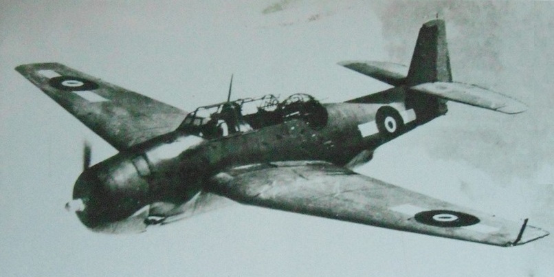
In December 1940 the US Navy placed an initial order for 286, subsequently multiplied, and deliveries began in January 1942 to VT 8. The same squadron took their TBF 1 Avengers into action for the first time during the Battle of Midway, where they did great damage for little loss, while 35 of the 41 old TBDs were shot down in a single engagement. By December 1943 Grumman had delivered 2293 Avengers, most of them being TBF 1Cs with the wing guns and provision for two underwing drop tanks. The Royal Navy received 402 of these Grumman built aircraft (for the first six months calling them Grumman Tarpons), with the US Lend/Lease designation of TBF 1B and the British name Avenger I. The first squadron, Fleet Air Arm No 832, was in action at the Battle of the Solomon Islands in June 1943, aboard the US carrier Saratoga. A further 63 TBF IBs were supplied to the RNZAF.

Grumman TBF-1C Avenger

Avenger NZ2505 was the first Avenger to arrive in NZ in 1943 and flew with RNZAF 30 Sqn. It was retired in 1959.

So important was the Avenger that a second source was arranged, to boost rate of output. As with the Wildcat fighter this second manufacturer was Eastern Aircraft division of General Motors. Between September 1942 and April 1944 Eastern delivered 2882 TBM 1 and 1C Avengers, almost identical to the Grumman 1 and 1C, and 334 TBM 1 were designated Avenger II when supplied to the Royal Navy.

In early 1943 Grumman built an XTBF 3 prototype with 1900 hp R 2600 20 engine. This version subsequently became the standard production Avenger, all made by East¬ern Aircraft (Grumman concentrating on the F6F Hellcat fighter). Between April 1944 and August 1945 Eastern delivered 4664 of this more powerful TBM 3 model, which also carried more fuel, had stronger wings equip¬ped to carry drop tanks, radar or rocket projectiles, and in most aircraft had the turret removed. The Royal Navy received 222 designated Avenger III.
The TBM-3E, almost the same as the earlier TBF, had a fuselage stretch of around one foot and a more powerful engine.

Flight 19 – Bermuda Triangle Article

In 1946 the Avenger was the first aircraft ever to carry early warning (AEW) radar, the Project Cadillac set that became APS 20. This became a standard interim service type, designated TBM-3W and 3W2, with no turret and rearranged interior.

TBF-3W

The TBM 3E was a post war rebuild which was put back into ‘remanufacture production’ during the Korean war, for the Royal Navy (100 Avenger AS.4), Royal Canadian Navy (115) and Aeronavale (96). The TBM 3S and 3S2 were antisubmarine strike versions for the Netherlands and Japan. The TBM-3U was a target towing version, and the TBM 3R was a seven seat COD (Carrier On Board Delivery) transport.
958 served with the Royal Navy.
All models were powered by Wright R-2600 Cyclone engine.
A total of 9839 aircraft were built.

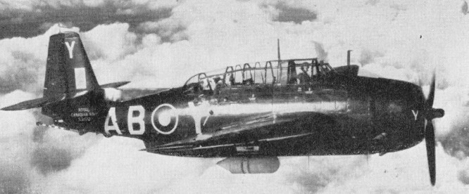
Avengers in service with the Royal Canadian Navy in 1955 were ex-U.S.N. aircraft, modified by Fairey Aviation of Canada. Some retain original ballshape gun turret at rear of glasshouse. Others are unarmed. All carry a radome cannister under starboard wing.

Royal Canadian Navy TBM-3

Gallery

TBF-1
Engine: 1 x Wright R-2600-8 Cyclone 1700 hp.
Max speed: 278 mph / 445 kph.
Service ceiling: 22,600 ft / 6890 m.
Wing span: 54 ft 2 in / 16.5m
Width folded: 19 ft / 5.8 m.
Length: 40 ft / 12.2 m.
Height: 15 ft 5 in / 5 m.
Wing area: 490 sq.ft.
Empty wt: 10,600 lb.
MTOW: 7053 kg / 17,600 lb.
ROC: 1075 fpm / 376 m/min.
Range: 1450 km / 905 sm.
Crew: 3
Armament: One .30 mg in cowling, one fixed .50 mg in each outer wing, one .50 mg in power-operated turret, one .30 mg in ventral hatch, bomb bay / one torpedo, one 2000 lb bomb or four 500 lb bombs

TBF-1C Avenger
Engine: 1 × Wright R-2600-20 Twin Cyclone , 1,900 hp (1,420 kW)
Wingspan: 54 ft 2 in (16.51 m)
Length: 40 ft 11 in (12.48 m)
Maximum speed: 275mph (442 kph)
Maximum range: 1000 miles (1610 km)
Service Ceiling: 30,100 ft (9,170 m)

TBM 3 / TBF
Engine: Wright R-2600-20 Cyclone 14, 1726 hp / 1305kW
Span: 16.51 m (54 ft 2 in)
Length: 12.2 m (40 ft 0 in)
Height: 16 ft 5 in / 5.0 m
Wing area: 489.977 sq.ft / 45.52 sqm
Weight empty: 10105.5 lb / 4583.0 kg
Gross weight: 8278 kg (18 250 lb)
Max speed: 232 kts / 430 km/h (267 mph)
Cruising speed: 128 kts / 237 km/h / 147 mph
Service ceiling: 23392 ft / 7130 m
Wing loading: 37.31 lb/sq.ft / 182.00 kg/sq.m
Range: 982 nm / 1819 km
Crew: 3
Armament: 3x MG cal.50 (12,7mm), 1x MG cal.30 (7,62mm), 907kg ord.

TBM-3
Engine: 1,750 h.p. Wright R2600-20
Wingspan: 54 ft. 2 in
Length: 40 ft. 11.5 in
Loaded weight: 16,761 lb
Max. speed: 261 mph
Ceiling: 22,600 ft.
Typical range: 1,130 miles at 151 mph
Crew: 2-3.

TBM-3E
Engine: 1 x Wright R-2600-20 Cyclone

TBM-3

Grumman G-58 F8F Bearcat

Grumman F8F-l Bearcat

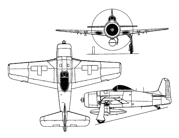
Conceived as a replacement for the earlier Grumman F6F Hellcat, the Grumman F8F Bearcat was also intended to surpass the Japanese Mitsubishi A6M ‘Zeke’ and later fighters. The provision of significantly more power than the R-2800 engine of the F6F Hellcat was impractical, so the design team concentrated upon producing a smaller lightweight aircraft which would ensure the performance required of a carrier-based interceptor. But although deliveries began before VJ-Day the Bearcat played no part in World War 2, most of the 8,000 or so examples on order being cancelled following the return of peace Despite being overtaken by events, the Bearcat did see service with the US Navy in substantial numbers, a total of 1,263 eventually being completed for this service, and many of these were later passed on to the air arms of France, Thailand and South Vietnam.

Standard production machines were capable of speeds well in excess of 644 km/h (400 mph), whilst the specially modified aircraft flown by stunt pilot Al Williams actually achieved a speed of 805 km/h (500 mph) at 5790 m (19,000 ft). Even more startling, however, was the rate of climb, one F8F-1 reaching 3050 m (10,000 ft) in just 94 seconds from brakes-off during November 1946 and setting a national record in the process.
Two prototypes, designated XF8F-1 and named Bearcat, were ordered on 27 November 1943, and the first flew on 31 August 1944. It marked a complete break with previous Grumman fighters, the only points of similarity being the portly fuselage and bluff engine, and the broad wing of generous area. Apart from those characteristics the XF8F was new, quite apart from being remarkably compact. The wing span was only 35ft l0in and the overall length 28ft 3in, and it was an extremely simple and uncluttered design. The single main spar ran straight from tip to tip and the engine firewall was in line with it. The centre of gravity of the loaded aircraft was eight inches in front of this point, emphasising how close-coupled the whole aircraft was. The wing was made in one piece, only the tips being arranged to fold straight up and over, and the top of the wing formed the floor of the cockpit. The seat was mounted straight on the wing, and pilots added their own personal cushion(s) so that they had a good view from the high teardrop canopy. The main landing gear retracted straight inwards, the small wheels with high-pressure tyres being housed in the wing root leading edge. A novel idea, later abandoned, was to arrange that, if the wing suffered vertical acceleration exceeding 8.5g, the outer 3ft of each wing would break off (preventing a catastrophic breakage at the root).
Figures taken during trials with the prototype Bearcat included a speed of 424 mph at 17,300ft and an initial rate of climb of 4,800 ft/ min. In October 1944 an initial series of 3,899 F8F-ls was ordered, with the 2,100-hp R-2800-34W engine, four 0.5-in guns and 169 lb of armour.
Deliveries of F8F-ls to the first operational squadron began in May 1945.

Thou¬sands were cancelled at VJ-Day, 770 built, and the first navy squadrons were still working up at this time (so the Bearcat’s baptism of fire came with the French in Indo-China and with Thailand. Grumman actually built 674 Dash-1s, followed by 224 F8F-lBs with four 20-mm cannon and finally 365 F8F-2s, similar to the -lB but with a taller fin (by 30.5cm), extra armour, a modified cowling and other changes. This total includes some (believed to be 12) -2N night-fighters with APS-19 radar were and a larger number (believed to be 60) -2Ps with only two cannon but a reconnaissance camera.
With an 1,863kW R-2800-E engine, an F8F-2 made a controlled climb from take-off to 3,050m in 92 seconds.

In addition to these new-build aircraft, close to 50 Bearcats were later retrofitted with APS-19 radar for night-fighter tasks as the F8F-1N and F8F-2N, whilst 60 more acquired cameras and became F8F-2P photographic reconnaissance aircraft, these having only two cannon installed.

Still in service with U.S.N reserve units in 1955, the F8F-2 Bearcat was in use as a “director ” for drones.

F8F-2 Bearcat

Ex-US Navy Bearcats were used by the French Armee de l’Air and the Royal Thai Air Force, playing a significant role in the conflict in Indo-China.

Some 30 years later a Bearcat took the world piston-engined speed record at 482 mph.

Gallery

XF8F-1
Wing span: 35ft l0in.
Length: 28ft 3in.

F8F-1 Bearcat
Engine: one 2,100-hp (1566-kW) Pratt & Whitney R-2800-34W radial
Maximum speed 678 km/h (366 kts / 421 mph) at 6005 m (19,700 ft)
Cruising speed: 141 kts / 262 km/h
Service ceiling 11795 m (38,700 ft)
Range 960 nm / 1778 km / 1,105 miles
Empty weight 3207 kg (7,070 lb)
Maximum take-off 5873 kg (12,946 lb)
Wing span 10.92 m (35 ft 10 in)
Length 8.61 m (28 ft 3 in)
Height 4.22 m (13 ft 10 in)
Wing area 22.67 sq.m (244 sq ft)
Wing loading: 53.10 lbs/sq.ft / 259.00 kg/sq.m
Armament: four 12.7-mm (0.5-in) machine-guns.
Crew: 1

F8F-1B
Engine: 1 x Pratt & Whitney R-2800-34W Double Wasp, 1566kW
Max take-off weight: 5873 kg / 12948 lb
Empty weight: 3207 kg / 7070 lb
Wingspan: 10.92 m / 35 ft 10 in
Length: 8.61 m / 28 ft 3 in
Height: 4.22 m / 13 ft 10 in
Wing area: 22.67 sq.m / 244.02 sq ft
Max. speed: 678 km/h / 421 mph
Cruise speed: 262 km/h / 163 mph
Ceiling: 11795 m / 38700 ft
Range: 1778 km / 1105 miles
Armament: 4 x 20mm cannons, 2 x 454kg bombs or 4 x 127mm missiles
Crew: 1

F8F-2D Bearcat
Engine: 2,500 hp Pratt & Whitney R2800-34W
Span: 35 ft. 7 in.
Weight: 9,537 lb.
Max speed: 425 mph
Armament: 4 x 20 mm. cannon
Range: 1,650 miles.

F-8F-2
Engine: Pratt & Whitney R2800-W, 2100 hp.

Grumman F6F Hellcat

In early 1941 Grumman designers had been studying the next generation, using one of the much more powerful engines that were available, such as the 1,600-hp Wright R-2600 Cyclone 14 or the 2,000-hp Pratt & Whitney R-2800 Double Wasp.

Grumman F6F Hellcat Article

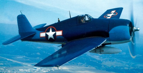
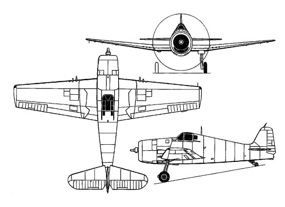
The fuselage was made much bigger, with a cross-section no longer circular but resembling a pear-shape. The huge squarish wing was lowered, partly to keep the landing gear reasonably short and still provide ground clearance for the larger propeller. The main landing gears were moved out to the wings, retracting rearwards with the wheels turning to lie flat just in front of the slotted flaps. The outer wings, with six 0.5-in guns, folded about skewed hinges as before. The overall impression was one of bluff pugnacious strength, accentuated by the blunt nose, with ducts for the oil cooler and supercharger intercooler under the engine. Contracts for the prototypes were placed on June 30, 1941, which meant that reports of aerial combat in Europe played a part in the design, and the first prototype, designated XF6F 1 and powered by a 1700 hp Wright R 2600 10 Cyclone, flew for the first time on June 26, 1942 from the Bethpage, Long Island factory, piloted by Selden A Converse. In the same month, a Zero had been forced down in the Aleutians and captured, so that further lessons could be incorporated, and the revised prototype, now designated XF6F 3 (another prototype, XF6F 2, later XF6F-4, was also built), made its first flight on 26 June 1942, powered by the R-2800. The bigger engine was the obvious choice, and — even though Grumman was building a completely new Plant 3 in order to make the new fighter — mass production got under way with amazing rapidity. Even as the factory was being built, assembly lines of F6F-3s took shape inside it, the first coming off the line and into the sky on 4 October 1942.
Orders for production F6F 3s had been placed in May 1942, and by the end of the year the first examples were being delivered to US Navy Squadron VF 9 on the newly commissioned USS Essex.
Designed to outperform the Zero in everything but manoeuvrability achieved in the A6M only at the expense of heavy armament and armour protection for the pilot and fuel tanks the F6F 3 was powered by a Pratt & Whitney R 2800 10W Double Wasp 18 cylinder air cooled two row radial engine with water injection. Construction was simple and robust for case of both production and maintenance, an all metal semi-monocoque with stressed skin incorporating armour protection for the pilot and a turnover structure. The wings used the characteristic Grumman folding system, pivoting about the front spar and folding back parallel with the fuselage, leading edge down. The operation was carried out manually, the locking pins being operated hydraulically from the cockpit and made safe by hand. The six 0.50 in (12.7¬mm) machine guns, mounted just outboard of the break line, were thus accessible with the wings folded. The main undercarriage legs also rotated through 90O to retract backwards into wing wells, covered by plates attached to the legs.
Compared with the Wildcat, the F6F 3 had 800 hp more power, was 97 km/h (60 mph) faster and had two more guns with almost double the ammunition (400 rounds per gun). Although considerably heavier, the Hellcat could climb to 4572 m (15000 ft) in under eight minutes and had a service ceiling of over 8230 m (37000 ft). Compared with the Zero it was faster, better armed and far more resistant to battle damage.
In order to concentrate on the Hellcat, Grumman sub contracted production of the Wildcat and the TBF Avenger to General Motors, and deliveries to both the US Navy and Marine Corps and the Fleet Air Arm, which named the type Hellcat I, mounted rapidly.
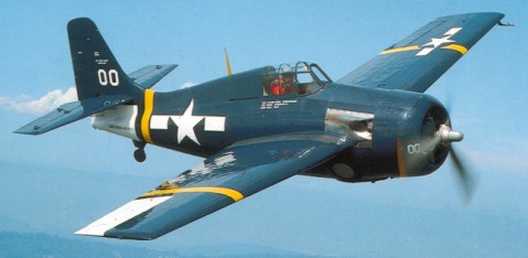
Named Hellcat, the F6F-3 was almost right from the start, the only major modifications being to tilt the engine slightly downwards, simplify the main landing-gear fairings and fit a Hamilton propeller with no spinner. Then production really rolled, starting with 4,403 F6F-3s, including 16 converted as F6F-3E night-fighters with an APS-4 radar pod on the starboard wing and 205 F6F-3N night-fighters with an APS-6 radar in a pod on the starboard wing. Late Dash-3s had the R-2800-10W rated at 2,200hp with water injection, and a flat bulletproof windshield.
During 1944 the F6F 3 (an eventual total of 4646) was replaced on the production lines by the F6F 5, using the same engine but with modified cowling and windshield and improvements to the control surfaces with spring-tab ailerons, strengthened tail surfaces, additional armour behind the pilot and a waxed high-gloss skin finish. Armament was increased, with fittings for a 454 kg (1000 lb) bomb under each wing centre section, racks for six rockets under the outer wings and, on later models, the inboard machine guns replaced by 20 mm cannon. The F6F-5 carried a search radar as the F6F-5E. This was the final produc¬tion version of the Hellcat, a total of 7860 being produced by November 1945, including 1189 F6F 5N night fighters with wing podded APS 6, photographic-reconnaissance (F6F-5P) versions, and 930 FAA Hellcat IIs.
The F6F-5K was a long-range radio-controlled pilotless drone conversion of the Hellcat. The modification was undertaken by the Naval Aircraft Modification Unit at Johnsville. Several were used in the Bikini operations.
The remaining variant was the F6F 6, powered by a 2100 hp R 2800 18W, which first flew in mid1944, but only two were built.
At the same time as the Hellcat began to enter service, the US Navy’s new Essex Class fleet carriers and Independence Class light carriers were coming into commission, and new aircraft and new carriers saw their first operational use in the summer of 1942 in a strike against the Japanese held Marcus Island. Alongside the Avenger torpedo bomber and Dauntless dive bomber and in partnership with the later F4U Corsair fighter, Hellcats fought their way across the Pacific as the island by island drive towards Japan continued.
Some late F6F-5s had two 20-mm cannon and four 0.5-in guns. The overall figure of 7,870 included 1,529 F6F-5N night fighters and about 200 conversions as F6F-5P photo aircraft. The totals for the F6F, like, those for the F4F, correct many that have been accepted since 1945.
In combat with the F6F, the Zero was at an enormous disadvantage. The unarmoured fuel tanks of the Japanese fighter were easily ignited by a short burst from the Hellcat’s six Brownings, and the Zero’s superior manoeuvrability was outweighed by the American fighter’s greater power and strength. Their most dramatic combat came in the Battle of the Philippine Sea, a carrier battle fought at extreme range on June 19/20, 1944. In the course of this epic encounter, 402 Japanese aircraft were destroyed, while six Hellcats were lost in the vicinity of the Japanese fleet and a further 17 splashed down with empty fuel tanks on the return journey. This decisive victory was known as the ‘Marianas Turkey Shoot’ by the US Navy and Marine pilots.
As well as flying from carriers, F6Fs were operated by shore based US Marine squadrons. The type also distinguished itself in Fleet Air Arm service, flying anti shipping strikes off the Norwegian coast, providing fighter cover during night attacks on the German battlecruiser Tirpitz, and becoming the standard FAA fighter in the Pacific. The Royal Navy received over 900 Hellcats including approximately 70 night fighters. These were designated F Mk II and NF Mk II. US Navy carrier borne Hellcats claimed a total of 4947 enemy aircraft shot down over 75% of all US Navy combat victories of the Second World War, and with a kill to loss ratio of over 19: 1. A total of 6477 Japanese aircraft were shot down by American carrier pilots. 4947 were destroyed by Grumman F6F Hellcats. The virtual annihilation of Japanese naval aviation represented the suc¬cessful completion of the Hellcat’s mission.

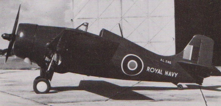
The Fleet Air Arm received 252 Hellcat Is (F6F-3), 930 Hellcat IIs (F6F-5) and 80 Hellcat NF.IIs (F6F-5N). Some were modified as FR.IIs (fighter-reconnaissance) or as unarmed PR.IIs. The combat record of the Hellcat speaks for itself. Though it did not get into action until 31 August 1943 this fighter destroyed 5,155 (not 4,947) of the US Navy total carrier-based score of 6,477 against the Japanese. Though perhaps not entirely typical, it gives a flavour of the F6F’s long-awaited ascendancy to note that in its first big battle, in the Kwajalein/Roi area on 4 December 1943, 91 F6F-3s met approximately 50 A6M Zeros and destroyed 28 for the loss of two aircraft.
After the war Hellcats continued in service, some as camera equipped F6F 5Ps, others as F6F 5K target drones and 5D drone directors. One of their last and least-known missions came during the Korean war, by which time they were obsolete as fighters. Remote controlled F6F 5Ks, filled with explosives, were launched from USS Boxer by Guided Missile Unit 90 in six attacks against North Korean targets, the first attack being carried out on August 28, 1952. The 5Ks were guided during the attacks by Douglas AD 2D Skyraider drone director aircraft.

The F6F-5 was the last operational version of the Hellcat, which was finally withdrawn from production in November 1945. The 10,000th Hellcat was delivered to the US Navy in March 1945 and final production amounted to 12,275.

Gallery

F6F 3
Span:13.06 m (42ft 10 in)
Length:10.24 m (33 ft 7 in)
Gross weight: 5643 kg (12441 lb)
Maximum speed: 604 km/h (375 mph).

F6F-5
Engine: 1 x Pratt & Whitney R-2800-10W Double Wasp, 1491kW / 1973 hp
Max take-off weight: 6991 kg / 15413 lb
Empty weight: 4152 kg / 9154 lb
Wing loading: 46.13 lb/sq.ft / 225.0 kg/sq.m
Wingspan: 13.06 m / 42 ft 10 in
Length: 10.24 m / 33 ft 7 in
Height: 4.11 m / 13 ft 6 in
Wing area: 31.03 sq.m / 334.00 sq ft
Max. speed: 330 kts / 612 km/h / 380 mph
Cruise speed: 146 kts / 270 km/h / 168 mph
Service Ceiling: 11370 m / 37300 ft
Range w/max.fuel: 1329 nm / 2462 km / 1530 miles
Armament: 6 x .50in / 12.7mm machine-guns, 2 x 454kg bombs or 6 x 127mm missiles
Crew: 1

Grumman G-18 / G-36 / F4F Wildcat

F-4F-3

Designed in 1937 by Robert L. Hall, the company’s first carrier-based fighter of monoplane configuration was designed to meet a US Navy requirement which originated in 1935, but it was not until July 1936 that the Navy ordered this aircraft, under the designation XF4F-2 (G-18).

Grumman F4F Wildcat Article

The model G-18 was powered by the Pratt & Whitney R-1830-66 Twin Wasp engine, a two-row, fourteen-cylinder radial. A Hamilton Standard two-position propeller was fitted. The armament installation was basically the same as that of the XF4F-1, with two 0.50 guns with 200 rounds each in the top of the engine cowling, and provision for two 100lb bombs under the wings. The gross weight of the aircraft was 5635lb, a substantial increase over the XF4F-1 biplane. The G-18 was ordered on 28 July 1936. Despite the substantial differences to the G-16, the designation XF4F-2 was applied. The prototype, BuNo 0383, was first flown on 2 September 1937. During trials it demonstrated a maximum level speed of 290mph, which was faster than the XF2A-1, but still below the USN requirement of 300mph.

The XF4F-2 was delivered to NAS Anacostia on 23 December 1937 for evaluation. During trials the prototype suffered from a series of snags and accidents. None of these was particularly serious, but their undermined the confidence of the USN. The XF4F-2 suffered repeated engine crankshaft failures. The arrestor hook proved too weak. On 24 February 1938 there was an on board fire when ballast bags in the aft fuselage began to burn. And on 11 April 1938 the XF4F-2 suffered a crash when the engine failed during a simulated deck landing. As a result, the US Navy selected the more reliable Brewster F2A-1 Buffalo for production, after NACA tests had suggested that minor aerodynamic improvements could boost the speed of the XF2A-1 by 30mph. The USN ordered 54 F2A-1s on 11 June 1938. Despite this setback, the USN continued to show interest in the F4F. This was probably partly due to its unwillingness to rely fully on the production of Brewster: The order for the F2A-1 was the first production contract for Brewster, and the manufacturer did not even possess a factory which was adequate for the production of aircraft. Grumman had already built the FF, F2F and F3F for the Navy, and the F4F showed some promise. A development contract was awarded in October 1938.
To overcome the shortcomings of the XF4F-2, a new prototype was built with a more powerful two-stage supercharged engine, and airframe revisions which increased wing span and brought changes to wingtips and tail surfaces. In this form the XF4F-3 flew for the first time on 12 February 1939.
In July 1936 the navy ordered the prototype XF4F-2, with one of the new 900-hp Pratt & Whitney R-1830 Twin Wasps at the front of a rather tubby fuselage which carried the monoplane wing an inch or two below the mid position. The R-1830S C5 G went into production in 1940 to power the Grumman F4F 3 Wildcat fighter. This was the first production aircraft with two stage supercharging. The hand¬cranked landing gear was re¬tained, and the pilot could look down through two windows in the floor of the comfortable cockpit. Bob Hall, designer of the faintly similar Gee Bee racers, took the XF4F-2 on its first flight on 2 Sep¬tember 1937. Armed with two 0.5-in guns and two 100-lb bombs, this showed promise but suffered from prolonged engine problems. First flown on 12 February 1939, the XF4F-3 had a com¬pletely revised airframe, with broad square-tipped wings and a much-improved tail. It also had a far better Twin Wasp, with a two-stage two-speed supercharger. Armament was increased to two 0.3-in in the fuselage and two 0.5-in in the outer wings. Though by far the heaviest Grumman fighter yet, the Dash-3 proved a fine aircraft, with excellent manoeuvrability, a speed of 333 mph and service ceiling of 33,500 ft. In August 1939 the navy ordered the first batch of 54 F4F-3s, with a longer fuselage, four 0.5-in guns in the wings and, later, armour and self-sealing fuel tanks. This order was soon in¬creased.
Grumman offered an export version of the F4F 3 ordered by the US Navy as the G 36A, a contract for 81 aircraft being placed on behalf of France’s Marine Nationale, and France added 81 of a version called the G.36A with Cyclone engines. Seven were in various stages of assembly when France fell and the entire batch was transferred to Britain which also placed a contract for 100 G 36As on its own account. Britain’s Fleet Air Arm put in British non-metric instruments and a throttle lever that worked in the normal sense (the French pulled the lever back for take-off). The six 7.5-mm French guns in the wings were retained.

They proved far better than any other fighter in the Fleet Air Arm, and opened their score on Christmas Day 1940 when two from 804 Squadron shot down a Ju 88 in the north of Scotland.

G-36A Martlet I

Whereas the French contract aircraft were powered by the 1,200 hp Wright R 1820 G205A Cyclone, Britain selected the Pratt & Whitney S3C4 G Twin Wasp of similar power. The first (French contract) G 36A flew on 11 May 1940 and entered British service as the Martlet I, a contractual change resulting in the British order being switched to the G 36B with folding wings, this entering service as the Martlet II (although the first 10 were accepted with fixed wings). The 30 F4F 3As that had been assigned to Greece were also taken into the Royal Navy inventory as Martlet IIIs, and with the passage of the Lend-Lease Act, 220 aircraft essentially similar to the F4F-4 but with the single stage R 1820 40B engine were assigned to the Royal Navy as Martlet IVs (F4F 4Bs), these becoming Wildcat IVs when British and US names were standardised in March 1944.

Churchill regarded the production of Fulmars vital and the greater need for land Spitfires, the diversion of resources to a new navalised variant would reduce Spitfire’s production numbers. To cover the gap until the Fulmar’s replacement (the Fairey Firefly) was able to enter service, Grumman Wildcats were ordered for the FAA. These entered service towards the end of 1940 as the Martlet, but these were unavailable in sufficient numbers, while Sea Hurricanes, without folding wings, were also not advanced enough as a solution.

The appearance of the A6M2 N float fighter in the Aleutians prompted US Navy interest in a float equipped version of the F4F 3 shipboard fighter. One example was therefore fitted with Edo designed and manufactured single step metal floats, and with auxiliary rudders mounted near the tips of the tailplane flew on 28 February 1943. The need for additional keel area aft was revealed by initial trials and a large ventral fin was added to improve yaw stability. The floats and their bracing struts raised the fighter’s weight by only some 500 lb (227 kg), and from calm water at normal loaded weight the F4F 3S could take off within 34 seconds. However, the dramatic effect of float drag on speed performance led to an earlier contract to complete 100 F4F 3 Wildcats as float fighters being cancelled.
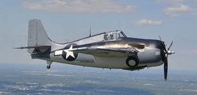
Altogether Grumman built 369 F4F-3s for the US Navy, followed by 95 Dash-3As with the R-1830-90 engine. Some were converted to F4F-3P photo air¬craft and BuNo 4038 was fitted with twin floats. The navy allotted the name Wildcat, thereby estab¬lishing the famous series of Grum¬man ‘cat’ fighters, and the British changed to the same name in January 1944. The chief drawback of the otherwise outstanding F4F-3 was its size, which did not fit too well with the constricted decks of the new escort carriers. Leroy Grum-man took two paperclips and, after bending them in various direc¬tions, stuck them into a pencil eraser. He thus proceeded to demonstrate the principle of what at first was called the ‘sto-wing’. By attaching the outer wings by oblique skewed hinges they were made to fold back on each side of the fuselage, upper surface out¬wards. The company made abso¬lutely sure it worked before com¬mitting it to production at the 163rd aircraft, subsequent delive¬ries being designated F4F-4s, or Martlet IIs. These had the 1,200-hp R-1830-86 engine and the heavy armament of six 0.5-in guns in the outer wings. They were by far the most important Allied fighters in the Pacific from Pearl Harbor until the summer of 1943. Grumman completed the last of 1,971 F4F-4s on the last day of 1942, subsequently needing every inch of floor for the TBF and F6F. Small numbers were built of the experimental Dash-5 to -8.
In January 1942 General Motors formed its Eastern Aircraft Divi¬sion to build aircraft in under-used car factories. In 1942 the manufacture of the Wildcat was transferred to the Eastern Aircraft Division of the General Motors Corporation. The first FM-1 Wildcat, assembled from parts supplied by Grumman, flew on 1 September 1942. The FM-1, fitted with a Pratt & Whitney R-1830-86 engine, was virtually the same as the F4F-4 (Wildcat IV). By 11 April 1944 the Eastern Aircraft Division had produced its 2,500th Wildcat.
Manufacture of the F4F-4 continued in slightly modified form as the FM 1 Wildcat, the R 1830 86 Twin Wasp engine being retained but wing armament being reduced from six to four 0.5 in (12,7¬ mm) guns and ammunition capacity being raised (from 1,440 to 1,720 rounds). The first FM 1 was flown on 31 August 1942, at Linden, New Jer¬sey, a total of 1,151 subsequently being built of which 312 were assigned to Britain as Martlet (later Wildcat) Vs.

The version of the Wildcat built in largest numbers by General Motors, however, was the FM 2, the first version of the fighter produced for the US Navy to standardise on the 1,350-hp R-1820-56 Cyclone engine. The FM 2 was the production version of the XF4F 8, two prototypes of which were built by Grumman with the first flying on 8 November 1942. Distinguished by its short cowling and redesigned, taller tail. FM-2 Wild¬cats had the oil coolers removed from the under surface of the centre-section to the cowling, which was revised in shape. The removal of the oil coolers permitted the installation of universal racks under the inner wings for bombs or auxiliary fuel tanks, six 0.5-in guns, and (from No. 3,301) six 5-in rockets. This version was called the Wildcat V by the Fleet Air Arm.

FM-2 Wildcat

A total of 4,777 FM 2 Wildcats was built, the last delivery in August 1945, of which 370 were assigned to Britain as Wildcat VIs.
Excluding prototypes a total of 7,898 F4Fs and FMs were built.

These were used operationally by the US Navy on a wide scale in the Pacific (FM-2 in particular serving as light escort carrier fighters), participating in the battles of the Coral Sea and Midway, and were used extensively in the attack on Guadalcanal. The type remained in first-line service until the end of the war. British Martlets initially replaced Sea Gladiators and, like their US Navy counterparts, remained operational until the end of the war.

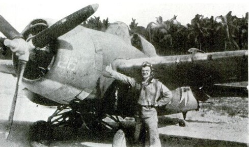
Lieut. Millard Thrash USNR 1944 at Guadalcanal after WASP sinking

Gallery

XF4F-2
Engine: Pratt & Whitney R-1830-66 Twin Wasp, 900-hp.
Wing span: 34 ft.
Armament: two 0.5-in guns & two 100-lb bombs.

XF4F-2
Engine: Pratt & Whitney R-1830-66 Twin Wasp, 1050 hp
Wingspan: 38 ft 0 in / 11.6 m
Length: 28 ft 9 in
Height: 11 ft 11 in / 3.6 m

XF4F-3
Engine: Pratt & Whitney R-1830 Twin Wasp.
Armament: 4 x 0.5-in mg.
Max speed: 333 mph.
Service ceiling: 33,500 ft.

G.36A Martlet I / Wildcat
Engine: Wright R-1820G 205A Cyclone, 1200 hp
Wingspan: 38 ft 0 in / 11.6 m
Length: 28 ft 9 in
Height: 11 ft 11 in / 3.6 m
Armament: six 7.5-mm mg.

F4F-3
Engine: Pratt & Whitney R-1830-76 Twin Wasp, 1200 hp
Wingspan: 38 ft 0 in / 11.6 m
Length: 28 ft 9 in
Height: 11 ft 11 in / 3.6 m
Empty weight: 4425 lb
Loaded weight: 5876 lb
Max speed: 325 mph / 523 kph

F4F-3A
Engine: R-1830-90.

F4F-3P
Photo air¬craft.

G-36 / F4F 3S
Max speed, 266 mph (428 kph) at 20,300 ft (6 185 m).
Initial climb, 2,460 ft/min (12,5 m/sec).
Max range, 600 mls (965 km).
Empty weight, 5,804 lb (2 633kg).
Loaded weight, 7,506 lb (3405 kg).
Span, 38 ft 0 in (11,59 m).
Length, 39 ft 1 in (11,91 m).
Height, 18 ft 13 in (5,53 m).
Wing area, 260 sq ft (24,15 sq.m).

F4F-4 / Martlet II / Wildcat
Engine: Pratt & Whitney R-1830-36/40 Twin Wasp, 1,200-hp / 895kW
Wing span: 38 ft / 11.58 m
Length: 8.76 m / 28 ft 9 in
Height: 2.81 m / 9 ft 3 in
Wing area: 24.15 sq.m / 259.95 sq ft
Max speed, 293mph (471 km/h) at 13,000 ft (3 965 m).
Cruise speed: 249 km/h / 155 mph
Initial climb, 3,050 ft/min (15,49 m/sec).
Ceiling: 12010 m / 39400 ft
Max range (clean), 890 mls (1432 km).
Empty weight, 5,425 lb (2461 kg).
Normal loaded weight, 7,580 lb (3 438 kg).
Armament: six 0.5-in mg, 2 x 45kg bombs.
Crew: 1

F4F-5

F4F-6

F4F-7

F4F-8

FM-1 Wildcat
Engine: Pratt & Whitney R-1830-86 Twin Wasp, 1200 hp
Wingspan: 38 ft 0 in / 11.6 m
Length: 28 ft 9 in
Height: 11 ft 11 in / 3.6 m
Max speed: 318 mph / 509 kph
Armament: 4 x 0.5-in mg.

FM-2 Wildcat V
Engine: Wright R-1820-56 Cyclone, 1,350-hp.
Armament: six 0.5-in guns, and (from No. 3,301) six 5-in rockets.
Max speed, 289 mph (465 km/h) at sea level, 319 mph (513 km/h) at 19,600 ft (5 980 m).
Time to 10,000 ft (3 050 m), 4.5 min.
Max range (clean), 780 mls (1255 km).
Empty weight, 5,542 lb (2 516 kg).
Max loaded weight, 8,221 lb (3 732 kg).
Span, 38 ft 0 in (11,59 m).
Length, 28 ft 9 in (8,77 m).
Height, 11 ft 5 in (3,48 m).
Wing area, 260 sq ft (24,15 sq.m).

Wildcat VI
Engine: Pratt & Whitney R-1830-56 Twin Wasp, 1350 hp
Wingspan: 38 ft 0 in / 11.6 m
Length: 28 ft 9 in
Height: 11 ft 11 in / 3.6 m

Grumman F4F-4 Wildcat