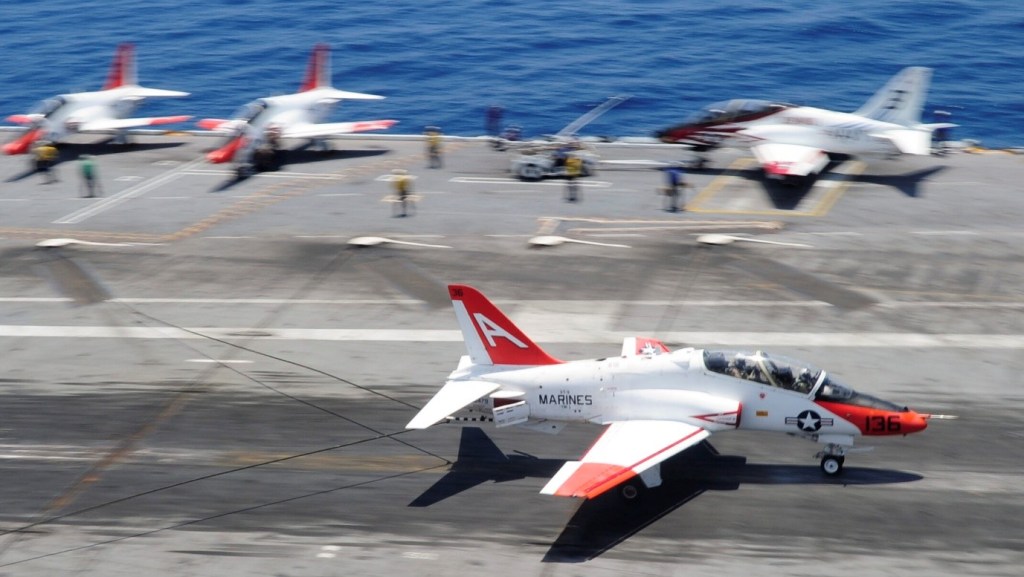
Derived from the British Aerospace Hawk advanced trainer, the US Navy’s carrier-capable T-45A Goshawk prototype was scheduled to fly before the end of 1987, with service entry due in 1990. The Hawk was selected in 1981 as the aircraft element of the new VTX-TS training system, and a fixed-price contract covering the first three production lots and 15 simulators was signed in May 1986. Total cost of the T-45TS package, including 300 production aircraft, two prototypes, simulators, computerised instruction and integration system, and logistics support is estimated at $4,500 million. British Aerospace is the principal airframe subcontractor, building the wings, rear fuselage, canopy, and flight controls, although final assembly and some component manufacture will be undertaken by McDonnell Douglas in the USA.
Changes from the basic Hawk design include a twin-wheel nose gear for catapult launching, a strengthened maingear to allow high-sink-rate landings, an arrester hook, rear side-fuselage airbrakes, and a cockpit modified to USN requirements. The empty weight of the T-45A will be 4,261kg, and maximum take-off weight 5,787kg, with an internal fuel load of 1,363kg. Approach speed will be 222km/hr (121 kt), maximum level speed Mach 0.85, and average fuel consumption 620kg/hr on a typical training sortie. Weapons delivery capability for armament training were be incorporated.
The T-45 Goshawk, of which the Navy owns 193 aircraft, is a jet trainer fleet used by the Navy and Marine Corps to qualify new pilots. Originally produced by what is now Boeing and derived from an earlier British aircraft made by BAE Systems, its first iterations joined the US Navy’s fleet in the 1990s.
BAe / Boeing T 45 C Goshawk Engine: Rolls Royce/Turboméca F 405-RR401 (Adour Mk. 871), 25977 N / 2648 kp Length: 39.272 ft / 11.97 m Height: 13.419 ft / 4.09 m Wingspan: 30.807 ft / 9.39 m Wing area: 179.651 sq.ft / 16.69 sq.m Max take off weight: 14083.3 lb / 6387.0 kg Weight empty: 9399.9 lb / 4263.0 kg Max. speed: 543 kts / 1006 km/h Initial climb rate: 6982.28 ft/min / 35.47 m/s Service ceiling: 42503 ft / 12955 m Wing load: 78.52 lb/sq.ft / 383.0 kg/sq.m Range: 999 nm / 1850 km Crew: 2 Hardpoints: 3
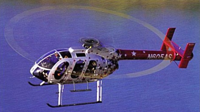
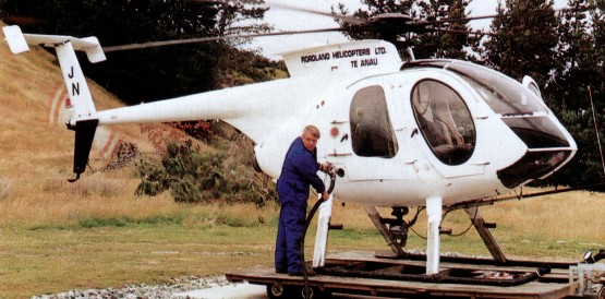
On 8 November 1994, McDonnell Douglas announced their plans to develop an eight-place version of their popular MD520N helicopter. They surprised the world’s press in January 1995 when they flew their new helicopter to Heli-Expo 95 in Las Vegas, Nevada. The prototype, then known as MD 630N (N630N, converted from MD 530F demonstrator), first flew 22 November 1994, 138 days after project approval. After their public debut at Heli-Expo the first year’s production was sold out on the first day.
Production go-head was given on 28 March 1995, at which time designation changed to MD 600N; and a prototype was first flown with production standard engine and rotor system on 6 November 1995.
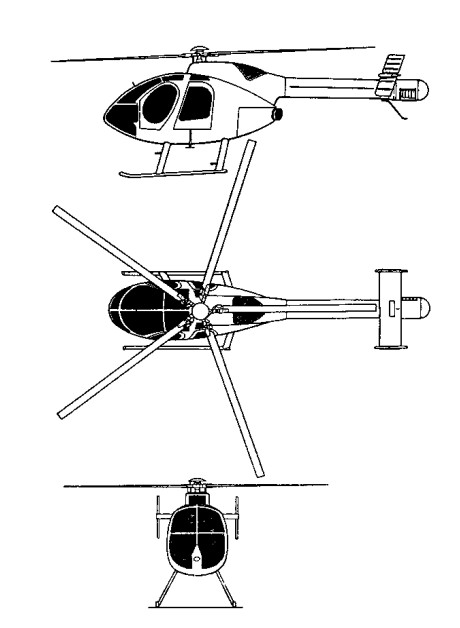
The 600N has a 33in lengthened fuselage centre section with double, centre opening doors, which gives access to a six-foot long flat floor with seating for five passengers in this rear cabin and three across the front seats. The complete fuselage of these helicopters are built under contract by helicopter manufacturer Kaman Aerospace. The six bladed fully articulated main rotor system shares many components with the MD500 series machines, and power comes from an 800-shp Rolls-Royce Allison 250-C47M turboshaft engine, which is derated to 600 shp for take-off and 530 shp for maximum continuous. The engine is equipped with FADEC as well as a manual backup hydro-pneumatic fuel system.
Production prototype (N600RN) first flown 15 December 1995, and became certification test vehicle leading to FAR Pt 27 certification, but was destroyed in ground fire 28 May 1996, following emergency landing after rotor/tailboom strike during abrupt control reversal tests. This resulted in changes to tailboom/rotor clearance; third prototype (N605AS) flown 9 August 1996; further accidents to N630N on 4 and 21 November 1996 and on 18 January 1997, all during autorotational descents, culminated in total loss and delayed certification and first delivery, originally scheduled for 18 December 1996, to 15 May and 6 June 1997, respectively. MD 600N certified on MD500 certificate. The FAA Certification was received on 15 May 1997. The first delivery was on 6 June 1997, N605AS, to AirStar Helicopters.
The 630N features a stretched MD 520N airframe (less than 1% new parts) by means of 0.76m plug aft of cockpit/cabin bulkhead and 0.71m plug in tailboom, combined with more powerful engine, uprated transmission and six-blade main rotor. Cabin has flat floor to assist cargo handling, and will feature quick-change interior configurations to suit multiple-use operators. Intended for civil, utility, offshore, executive transport, medevac, aerial news gathering, touring, law enforcement and other noise-sensitive operations; also adaptable for armed scout, utility and other military missions.
Powered by one 603kW Rolls-Royce 250-C47M turboshaft, derated to 447kW for T-O (5 minutes) and 395kW maximum continuous, with FADEC. Transmission manufactured from WE43A magnesium alloy for lower weight, greater strength and enhanced corrosion resistance, rating 447kW. Fuel contained in two crashworthy bladder tanks in lower fuselage, total capacity 440 litres, of which 434 litres are usable.
The electrical system comprises 28V 200Ah starter-generator and 28V 17Ah Ni/Cd battery. 24V auxiliary power receptacle inside starboard cockpit door standard.
In July 1998, Boeing completed a year-long envelope expansion programme for the MD 600N leading to FAA approval for operation at a density altitude of 2,135m at a T-O weight of 1,746kg and at a density altitude of 1,220m at a T-O weight of 1,860kg. Other performance enhancements approved by the FAA included provision for doors-off operation at speeds up to 213km/h, operation at temperatures -40°C/52°C, lifting up to 968kg on the external cargo hook, making slope landings up to 10° in any direction, operation with emergency floats and for installation of a movable landing light and additional wire strike protection on the fuselage. The MD 600N also completed HIRF trials at NAS Patuxent River, Maryland. Yaw-stability augmentation system (Y-SAS) was under development during 2000, aimed at reducing pilot workload during extended flights and in turbulent conditions.
Total of 68 registered by May 2003. Launch customer AirStar Helicopter of Arizona (two, of which first delivered 6 June 1997); Saab Helikopter AB of Sweden and Rotair Limited of Hong Kong ordered one each in June 1995; other customers include Guangdong General Aviation Company (GGAC) of the People’s Republic of China, which took delivery of one MD 600N in November 2000, during Airshow China 2000 in Zhuhai, Los Angeles County Sheriff’s Department Aero Bureau (three), Orange County, California, Sheriff’s Department, Indianapolis, Indiana. Police Department (one), Presta Services of France (one), Turkish National Police, which ordered 10 in December 2000 for delivery during 2002 (subsequently postponed to 2003), UND (University of North Dakota) Aerospace (one), West Virginia State Police (one) and the US Border Patrol (45, of which 11 delivered by end of 1998. when procurement halted pending evaluation of UAVs for border patrol role). Deliveries totalled 15 in 1997, 21 in 1998, six in 1999, seven in 2000, two in 2001 and two in 2002.
Costs: US$1.315 million (2002).
February 19, 1999 : Boeing sold MD commercial line to RDM The dutch company bought the ex Mc Donnell Douglas models MD 500E and MD 530F single-engine helicopters with conventional tail rotors, the MD 520N and MD 600N single-engine NOTAR helicopters and the MD Explorer series of twin-engine, eight-place helicopters.
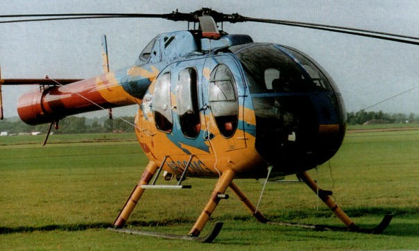
Military variants known as Defenders (AH-6E, MH-6F) carry TOW missiles, FLIR, mast-mounted sight, etc. The Model 530 Defender (has refined aerody¬namics and more power the OH-6), and AH-6 (Model 530 version for US Special Forces).
February 19, 1999: Boeing sold MD commercial line to RDM The dutch company bought the ex Mc Donnell Douglas models MD 500E and MD 530F single-engine helicopters with conventional tail rotors, the MD 520N and MD 600N single-engine NOTAR helicopters and the MD Explorer series of twin-engine, eight-place helicopters.
MD 530N
Commercial MD 520N and uprated (485 kW Rolls Royce 250-C30) MD 530N NOTAR helicopters announced February 1988 and officially launched January 1989. The first production prototype MD 530N (N530NT) flew on 29 December 1989, but this variant not pursued.
Flight testing of the MD 530N indicated capabilities greater than expected. With only 25.2 hours logged, a series of aerobatic manoeuvres were performed during June 1990, including loops, rolls, hammerheads and Split ‘S’ manoeuvres. In other tests the envelope was expanded to a maximum internal gross weight of 33500 lb / 1520 kg.
MD530F Engine: 1 x Allison 250-C30, 650 shp Instant pwr: 313 kW Rotor dia: 8.35 m MTOW: 1405 kg Useful load: 685 kg Max cruise: 135 kts Max range: 381 km HIGE: 14,300 ft HOGE: 12,000 ft Crew: 1 Pax: 3 Seats: 5
530MG Defender Engine: 1 x Allison 250-C30 Installed pwr: 317 kW Rotor dia: 8.4 m Fuselage length: 9.8 m No. Blades: 5 Empty wt: 664 kg MTOW: 1610 kg Payload: 901 kg Max speed: 240 kph ROC: 505 m/min Ceiling: 4200 m HIGE: 2315 m HOGE: 1770 m Fuel cap (+aux): 240 lt ( 80 lt ) Range: 443 km Crew: 1 Pax: 5
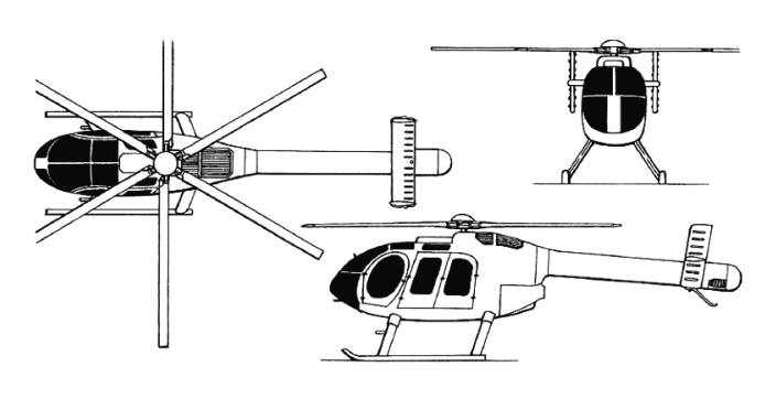
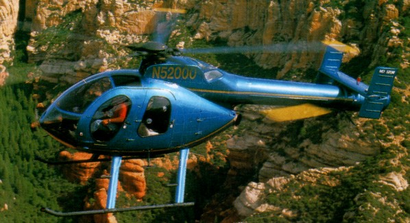
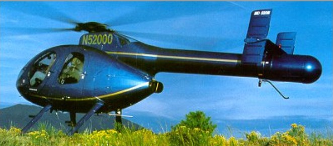
In 1976 engineers at McDonnell Douglas Helicopter Company (then Hughes) decided to explore the theories of Henri Marie Coanda (1885-1972), a Romanian-born aeronautical engineer and inventor, who put forward the concept that air flowing over a curved surface tends to follow the curve of that surface. The “Coanda Effect” is seen working when air flows over the surface of an airfoil. Under this effect, the aerody¬namics of the tailboom itself could be tapped to provide the bulk of the anti-torque force required. It is this principle which is at the heart of the NOTAR system embodied in the MD520N. The front half of the helicop¬ter is virtually identical to the MD 500E, but in place of a conventional tailboom and tail rotor mechanism, the MD 520N has a variable pitch fan totally enclosed within the tailboom, circulation control slots on the side of the boom, and vertical stabilizers and direct jet thruster. The variable pitch fan is driven off the back of the Allison 250-C20R turboshaft engine and, with help from the main rotor system down-wash, draws air via a grill into the enclosed tailboom, and provides low-pressure, high-mass airflow. Air is forced out through the circulation slots on the right side of the boom. Air exits the slots at about four times the velocity of the rotor downwash, which keeps the downwash attached to the curvature of the boom, resulting in the horizontal equivalent of lift, just like a vertical wing, and the Coanda Effect generates anti-torque force.
The direct jet thruster is located at the end of tailboom on the left side, and provides directional control plus assists with anti-torque. Even the engine exhaust stack helps out here, as it is canted to the left. However the bulk of the anti-torque required (eg 60-70 percent in hover) is provided by the Coanda Effect. Directional control above in forward flight above about 20 knots comes largely from the left vertical stabilizer, which is linked to pilot’s pedals. The effectiveness of this system is such that the MD 520N is approved for hovering in 30 knot crosswinds, and has been flown sideways at speeds signifi-cantly higher.
The first flight of an OH-6A NOTAR concept-demonstrator was made on 17 December 1981. The commitment to full-scale development and production was made in 1987. An extensive modifications during 1985 with second blowing slot, new fan, 250-C20B engine and MD 500E nose, led to flight testing resuming on 12 March 1986 and completed in June. The demonstrator was retired to US Army Aviation Museum, Fort Rucker, Alabama, October 1990.
Commercial MD 520N and uprated (485 kW Rolls Royce 250-C30) MD 530N NOTAR helicopters announced February 1988 and officially launched January 1989. The first production prototype MD 530N (N530NT) flew on 29 December 1989, but this variant not pursued.
First flight 520N (N520NT) on 1 May 1990 and first production 520N 28 June 1991. The 520N was certified on 12 September 1991 on the MD500 type certificate and the first production aircraft 520N (N521FB) delivered to Phoenix Police Department 31 October 1991. MD 520N set new Paris to London speed record in September 1992, at 1 hour 22 minutes 29 seconds.
The structure is the same as the MD 500E/530F, except graphite composites tailboom; metal tailplane and fins; new high-efficiency fan with composites blades fitted in production aircraft. NOTAR system components now have twice the lifespan of conventional tail rotor system assemblies. During 1993, NOTAR system components’ warranty increased from two to three years. Thicker fuselage skins, to reduce surface rippling, was to be introduced during 2001.
The single Rolls-Royce 250-C20R turboshaft, derated to 317kW for T-O (5 minutes) and 280kW maximum continuous. Improved, heavy-duty transmission, rating 447kW, derated to 317kW for T-O, 280kW maximum continuous, on production aircraft from June 1995. Fuel capacity 235 litres.
Believed to be the quietest turbine helicopter, based on FAA certification test noise figures, the main rotor rpm 477; main rotor tip speed 208m/s; NOTAR system fan rpm 5,388. A redesigned diffuser in NOTAR tailboom and revised fan rigging was introduced from early 2000 and available for retrofit; combined with uprated Rolls-Royce 250-C20R+ engine; these improvements increase the aircraft’s payload capability,
Customers had a total of 99 registered by mid-2002. Four delivered in 2000, two in 2001 and four in 2002. Law enforcement agencies flying MD 520Ns include Phoenix, Arizona (first operator; two more delivered in early 2002); Burbank, Glendale, Huntington Beach, Los Angeles, Ontario and San Jose, California; Hernando County, Florida; Orange County, Florida; Jefferson County, Kentucky, which took delivery of one in March 2002; Prince George County, Clinton, Maryland, which took delivery of two on 4 October 2000; Hamilton County, Ohio, which has seven 520Ns; El Salvador, whose Policia Nacional Civil took delivery of two in 1996; San Juan, Puerto Rico; Honolulu, Hawaii; and Calgary, Alberta, Canada. Other operators include the Tata Group of Mumbai, India, Weetabix Ltd, UK, and Belgian Gendarmerie (two). The unit cost was US$980,000 (2002).
Héli-Max Ltée from Trois-rivières, Québec, Canada was the first Canadian operator of MD520N model. They bought 6 of them.
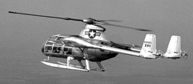
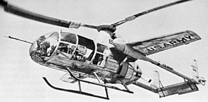
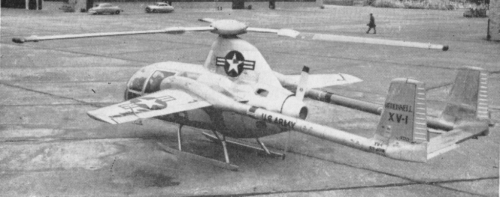
Initially designated XL-25 in the liaison aircraft category, then XH-35 in the helicopter class, and finally XV-1 as the first type in the new vertical lift category of aircraft designations, this machine worked on the unloaded rotor principle. Designed by Friedrich von Doblhoff, the Austrian helicopter pioneer responsible for the wartime WNF 342, the XV-1 was the result of an experimental programme undertaken jointly by McDonnell, the US Army Transportation Corps, and the USAF Air Research and Development Command.
Initiated by a Letter of Intent dated 20 June, 1951, the XV-1 project proceeded through mock-up inspection in November 1951, and the first aircraft (53-4016) was completed some 22 months later.
Combining the features of a twin-boom, twin-tail, fixed-wing aircraft with those of a single-rotor helicopter, the XV-1 was powered by a 525hp / 391kW Continental R-975-19 seven-cylinder radial. For vertical flight this engine drove two compressors which fed air through tubes to small pressure jets at the tips of the three-blade rotor, with the pressure jets operating on the principle of ignition and expansion of the fuel gases. For forward flight, the engine drove a two-blade pusher propeller mounted aft of the fuselage between the tail booms while the rotor autorotated. The XV-1 was intended to take-off and land as a helicopter, with transition from helicopter flight mode to conventional flight being made by transferring power from rotor to propeller as soon as the forward speed exceeded the stalled speed of the wing. Side-by-side accommodation was provided for a pilot and a co-pilot with room behind them for test instrumentation. Alternatively, accommodation could have been provided for a pilot and three passengers or a pilot and two stretchers.
The 9m long fuselage, mounted on skid landing gear, and mid/high-set wings mounted twin tailbooms with twin vertical surfaces (about 3m in height), inter-connected by tailplane and elevator.
The 7.9m span fixed wing featured a slight sweep on both the leading and trailing edges, although the angle of sweep was greater on the leading edge. It was also designed with a high aspect ratio and joined the fuselage at the same level as the top of the cockpit, directly below the mounting for the upper rotor. The wing terminated in the fuselage into a large bulbous housing on either side of the fuselage.
Project test pilot John R. Noll began tethered hover flights on 11 February, 1954, but difficulties with the pressure jet system delayed initial free flight until 14 July, 1954. The first successful transition from helicopter flight to conventional flight was made on 29 April, 1955. The flight test programme revealed several design deficiencies which were progressively corrected through the introduction of such modifications as a cut-down rotor pylon, small anti-torque rotors fixed to the end of each taitboom, redesigned landing skids, and other minor detail changes. During the preceding months, the second XV-1 (53-4017) had joined the flight trials programme. This machine differed from the first prototype in having a bulkier but streamlined undercarriage and cut-down rotor pylon to reduce interference drag. Numerous detail improvements, including the addition of a small steering rotor behind each boom, were progressively incorporated.
In evaluating the program, the consensus was that the basic concept was sound, but the piston engine powerplant could not provide the needed performance to optimize the design. It was felt that use of a gas turbine engine in this application would solve the problem.
Although on 10 October, 1956, the second prototype XV-1 had become the world’s first rotary wing vehicle to reach a speed of 322km/h, the gain in performance over conventional helicopters did not warrant the added complexity of the convertiplane configuration. Furthermore, the potential of the McDonnell XV-1 was seriously limited by its use of a piston engine instead of gas turbines as adopted to power European convertiplanes which preceded or followed it.
The programme was terminated in 1957 after the two prototypes had been flown for a total exceeding 600 hours. The first XV-1, 53-4016, then went to the Army Aviation Center Museum at Fort Rucker, Alabama, and the second, 53-4017, was donated to the Smithsonian Institution’s National Air and Space Museum, in Washington, DC.
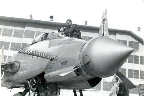
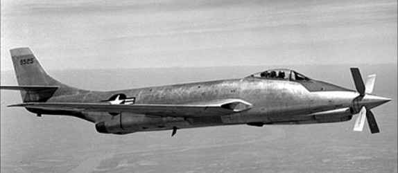
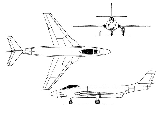
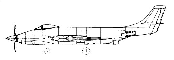
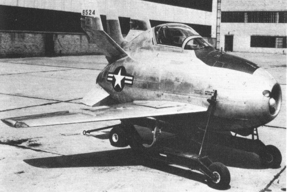
Designed to meet a requirement for a single-seat long-range escort fighter, the XF-88 was recipient of a contract for two prototypes on 14 February 1947. Powered by two 3,000 lb st (1361 kgp) Westinghouse XJ34-WE-13 turbojets, the first XF-88 was flown on 20 October 1948, but proved seriously underpowered. The second XF-88 was therefore fitted with two XJ34-WE-22 engines fitted with short afterburners which boosted thrust to 3,600 lb st (1 633 kgp), a change in designation to XF-88A accompanying this modification.
Performance was still insufficient, but the XF-88 was considered by the USAF to possess development potential and a Letter of Intent was issued covering further evolution of the basic design into what was eventually to become the F-101 Voodoo.
The first prototype was then recast as the XF-88B testbed for the Allison XT38 turboprop, with which it undertook many flights from April 1953 with 27 different propellers featuring varying numbers of blades in diameters between 4 and 10 ft (1.2 and 3.05 m). The XF-88s airframe then went forward to provide the structural and aerodynamic basis for the F-101 interceptor and reconnaissance fighter.
Engines: 2 x Westinghouse J34-WE-13 turbojets, 3000-lb (1361-kg) thrust Max speed, 641 mph (1 032 km/h) at sea level Time to 35,000 ft (10 670 m), 14.5 min Range, 1,737 mls (2 795 km) Empty weight, 12,140 lb (5 507 kg) Normal loaded weight, 18,500 lb (8 391 kg) Span, 39 ft 8 in (12,09 m) Length, 54 ft 1.5 in (16,50 m) Height, 17 ft 3 in (5,26 m) Wing area, 350 sq ft (32,52 sq.m)
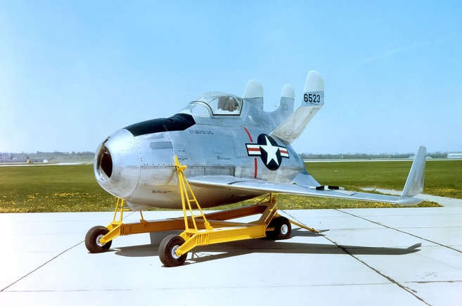
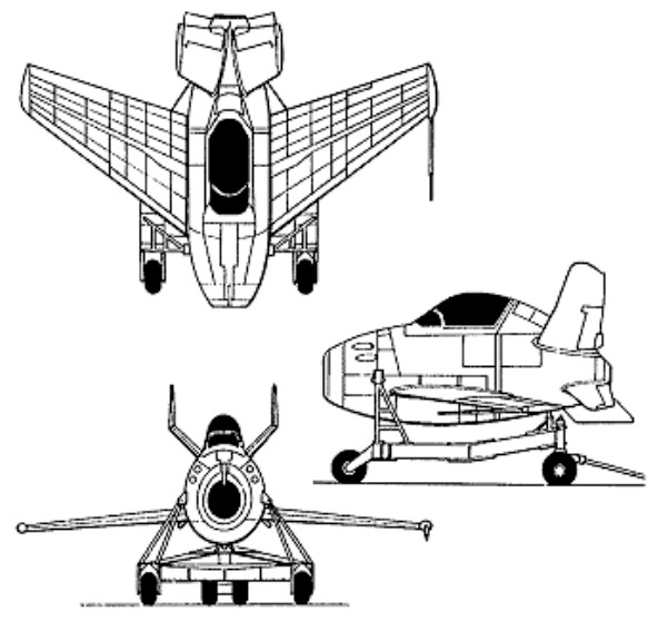
McDonnell proposed a ‘parasite’ (‘symbiote’) fighter had to be small enough to be carried aloft by a bomber and released as required. As early as 1942 McDonnell had proposed such a type as the MX-472 for semi-external carriage by the B-29, and further evolution of the concept resulted during 1945 in four variants of the Model 27 design for internal carriage by the Northrop B-35 and Convair B-36 heavy bombers. Under the spur of early ‘Cold War’ events, McDonnell reworked the Model 27 into the XF-85 Goblin. Designed under the leadership of Herman D Barkley, the XF-85 the subject of a Letter of Intent for two prototypes on 9 October 1945. The XF-85 was to be stowed in the number one or four bomb bay of the B-36 intercontinental bomber. Over target, it would be dropped free to protect the B-36 from enemy interceptors.
The fuselage was virtually filled by the 3000-lb (1361-kg) thrust Westinghouse J34-WE-7 turbojet and its fuel plus the four 0.5-in (12.7-mm) machine-guns and their ammunition, the pilot being seated astride the engine under a bubble canopy immediately aft of the hook that permitted aerial release and recovery of this tiny fighter. The wings were swept at 37 degrees and arranged to unfold from their vertically stowed position, which gave the fighter a ‘hangared’ width of only 5 ft 4.75 in (1.64 m), for an extended span of 21 ft 1.5 in (6.54 m) after being lowered from the parent aircraft. The fighter was intended to be launched from and recovered by a retractable trapeze which was to be extended beneath the parent bomber, no undercarriage being fitted.
In 1947, indoor tests were begun to evaluate the mating arrangement between the Goblin and a mock-up of a B-36 fuselage. On 9 November 1947 the first of two XF-85s was disassembled at the manufacturer’s St Louis plant and flown aboard a C-97 transport to Moffett Field, California, for wind-tunnel tests. While being positioned in the tunnel, the aircraft fell 12.2 m, was badly damaged, and had to be returned to St Louis, being replaced at Moffett by the second machine.
On 5 June 1948, this second XF-85 was transported to Muroc AFB, California, and, with no B-36 airframe available for evaluation of the parasite fighter concept, experiments began using an EB-29B Superfortress. Ed Schoch, a former US Navy F6F Hellcat pilot with four air combat kills in the Pacific war, was the only man ever to fly the XF-85.
Flight trials were initiated by the second prototype which was powered by a 3,000 lb st (1361 kgp) Westinghouse J34-WE-37 turbojet. After five captive flights on the trapeze of a specially modified Superfortress (EB-29B), the XF-85 was launched at 20,000 ft (6 095 m) on 23 August 1948, this first free flight terminating in an emergency landing. On his first attempt on 23 August 1948, Schoch was attempting to re-engage the bomber’s trapeze when he slammed into it, shattering his canopy, ripping his helmet off, and knocking him unconscious. Schoch recovered in time to make a shaky landing on the XF-85’s underside skid in the Muroc desert, damaging the plane.
The second flight on 14 October 1948, resulted in a normal mid-air drop and subsequent hook-up. Three more times, however, struggling to manoeuvre the tricky Goblin, Schoch was forced to make belly landings in the desert rather than regain his link-up with the Superfortress.
On 8 April 1949, the original XF-85 made its first and only flight. In budget-lean 1949, the XF-85 programme was quietly terminated after 2 hr 19 min of test flying, although the Strategic Air Command eventually became interested in the parasite fighter concept when it became possible to carry an RF-84K aboard a B-36. The first XF-85 is on display at the Air Force Museum in Dayton, Ohio, while the second is at the Strategic Air Command Museum in Omaha, Nebraska, displayed in inaccurate markings with a spurious tail number.
Max speed (calculated), 664 mph (1 068 km/h) Combat endurance, 30 min Empty weight, 3,740 lb (1 696 kg) Loaded weight, 4,550 lb (2 064 kg) Span, 21 ft 1½ in (6,44 m) Length, 14 ft 10.5 in (4,53 m) Height, 8 ft 3.25 in (2,56 m) Wing area, 90 sq ft (8,36 sq.m)
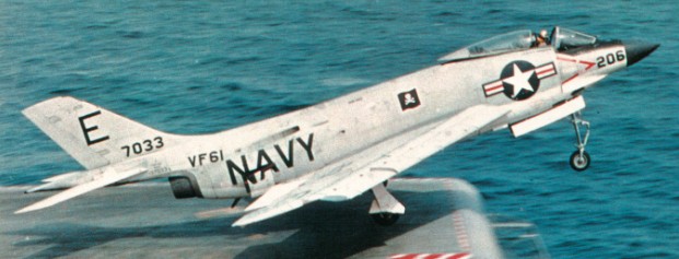
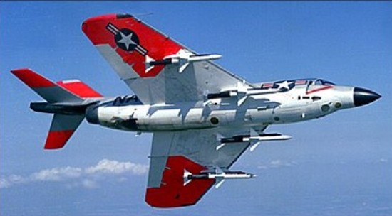
The prototype of the Demon naval fighter first flew on 7 August 1951 but proved to have poor stability, poor forward visibility and a low roll rate. These faults were corrected on the initial production model, but the poor reliability and performance of the J40 engine meant that most of the 58 built never flew.
The airframe had mid-set wings, swept-back at 45 degrees, swept-back tail surfaces and one-piece all-moving tailplane. The wings were fitted with leading edge slats and trailing edge slotted flaps. Airbrakes were in the upper surface of each wing root trailing edge and on the sides of the rear fuselage. The outer wings fold upward for storage. In-flight fuelling is fitted.
The tricycle undercarriage had a single wheel on each unit, the mains retracting inwards into the wings, and the nose wheel retracting rearward.
By June 1955 the F3H 2 had been produced with the Allison J71 engine, which still gave limited power. A modified afterburner system gave power in the range needed to make safe carrier landings.
They served with the US Navy in three versions – F3H-2N all-weather fighter, F3H-2M missile-armed day fighter, and F3H-2P for photo-reconnaissance.
The first naval fighter to be armed with guided missiles was the F3H-¬2M.
F3H-2 Demon Engine: 1 x Allison J71-A-2E turbo-jet, 62.23kN / 14,250 lb with afterburner Wingspan: 10.77 m / 35 ft 4 in Wing area: 48.22 sq.m / 519.04 sq ft Length: 17.96 m / 58 ft 11 in Height: 4.44 m / 14 ft 7 in Max take-off weight: 15377 kg / 33901 lb Empty weight: 10039 kg / 22132 lb Max speed: 730 mph at SL Max ROC: 12,800 fpm Service ceiling: 13000 m / 42650 ft Range w/max.fuel: 2205 km / 1370 miles Armament: 4 x 20mm cannons, 2722kg of weapons Crew: 1
F3H-1N Demon Carrier-based day and night fighter Engine: Westinghouse J40-WE-22 turbojet, 7,500 lb with afterburner Wingspan: 35 ft. 4 in Length: 59 ft Loaded weight: about 23,370 lb Max speed: over 750 m.p.h. Ceiling: 45,000 ft. Range: about 2,000 miles. Armament: 4×20 mm. cannon Crew: 1
F3H-2N Engine: Allison J71-A-2 turbojet, with afterburner, 9,700 lb. thrust
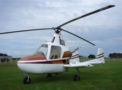
A two-seat light autogyro, the actual prototype J-2, designed by D.K.Jovanovich, first flew in June 1962. Deliveries of production aircraft began in 1970 and by early 1972 a total of 83 had been built. Power was provided by a 180hp Lycoming O-360-A2D engine.
In 1974 Aero Resources took over production of the J-2 two-seat light autogyro from McCulloch Aircraft Corporation. A version known as the Super J-2 was developed from the J-2, powered by a 180hp Lycoming O-360-A2D flat-four engine.
The J-2 has a Hughes 300 three-blade rotor system (wind-driven and inverted) and is powered by a 180 hp Lycoming pusher engine. This gyro is capable of a “jump” lift-off with the aid of its powerful pre-rotator.
Aero Resources Inc assumed responsibility in 1974 for continued production of the J-2 gyroplane, designed by D. K. Jovanovich, and manufactured previously by McCulloch Aircraft Corporation. It also developed an improved version, with 200 hp engine, designated Aero Resources Super J-2.
The J-2 is now classified as a Class 2 Microlight (it was a full C of A Aircraft) so can be flown on Microlight Gyroplane Licence.
Patrick Lewis I am an ex US Army pilot and after a voluntary RIF in 1970 at the end of my second Vietnam tour emigrated to Australia. I worked for several helicopter companies there and was offered a position with Hawker de Havilland based at their Bankstown GA airport during the mid 1970s. HdH Had purchcased 8 J-2s and needed an experienced rotory wing instructor pilot for sales demonstrations and flight training. My first job was to draft a flight manual sylabus that satisfide The senior examiner. The first J-2 arrived with an instructor pilot who checked out HdHs test pilot who in turned checked me out. I then checked out the local rotory examinar who then signed me off as a qualified instructor. HdH mechanics outfitted a J2 with an extra fuel tank and I made sales demonstration trips from Melbourne in the south to the sheep stations in the Darwin area and on to the North west cattle stations.
Jeff Jacobs In 1971 I was a young fixed-wing CFI working for Bel-Air Aviation at Long Beach CA, the first dealer and school for the J-2. I had no prior rotor experience but was being trained to fly and instruct in the J-2. I had soloed the J-2 a few weeks earlier, and on 5/5/71 my boss and instructor Ken McGuire and I flew N4303G from Long Beach to Compton for more practice. We touched down in a light crosswind, and despite the slow speed I lost directional control and the aircraft rolled over on the runway. It was the third J-2 landing rollover accident in three months, which as I recall was almost half the fleet built to that time. FAA ordered modification to the J-2’s nosegear, and that summer the company flew me out to the factory at Lake Havasu where I flew with Bill Evans in a modified J-2.
Bill Evans I went to work for McCulloch Aircraft in 1969 and at the time the company was located in El Segundo,CA. At that time the J-2 was just undergoing it’s final FAA certification and later on the entire operation was moved to Lake Havasu City, AZ. I was there for two years until they moved back to Gardena,CA and it then became Aero Resources. During my time in LHC I was doing the Flight Training and later became an FAA designated pilot examiner for Gyroplanes. I also was doing Production Flight Test and Experimental flight test for the company. I stayed on with the company until 1974 when they finally closed their doors. This was at the Van Nuy, CA airport. I think my total time in the J-2 was around 2200 hours. I flew the J-2 at the Paris Air Show and all over France. Also crossed the English Channel and did some flying in England as well. All and all it was a really fun aircraft to fly but had so many limitations when it came to performace. One of the biggest problems was the noise it produced. This really plagued the engineering department and nothing seemed to help. We had to wear special David Clark headsets and still the noise level in the cockpit was deafening. We did experiment with a 200 HP Lycoming engine and also a 3 bladed constant speed Hartzell prop. These improvement helped a little but in the end, it still did not have the desired performance. It had a very limited range with a lot of unuseable fuel left. The required distance for takeoffs was far more than acceptable. We were able to land in off airport locations but with the wood props it was usually an invitation to some major damage. The landing gear struts would some times remain extended or be uneven and this will make landing sometimes very exciting if you didn’t expect it. We did develop several techniques that would enhance both the take and landing performance but was never able to get them certified.
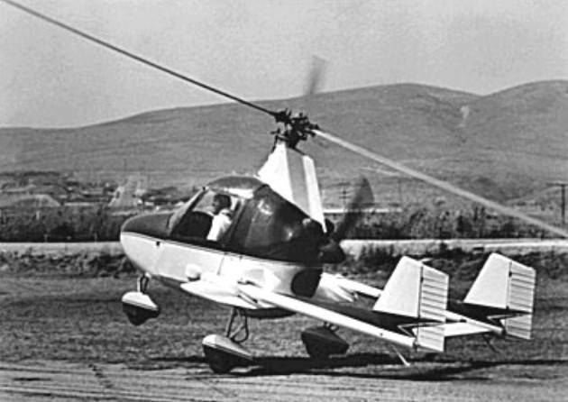
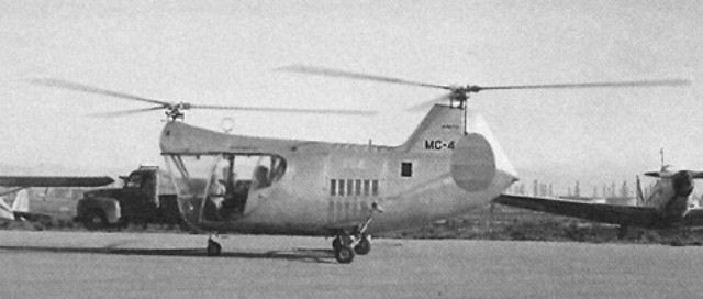
In 1949 Helicopter Division of McCulloch Motors Corporation appointed as chief designer D. K. Jovanovich, formerly of Helicopter Engineering and Research Corporation, who developed his JOV-3 as McCulloch MC-4 tandem rotor two-seat helicopter, first flown Los Angeles March 20, 1951.
This was the first tandem-rotor helicopter to be certificated by the U.S. Civil Aeronautics Administration for commercial use, and is also one of the smallest helicopters to be built with a tandem layout. Its development began in 1946 with the Helicopter Engineering and Research Corporation headed by D.K. Jovanovich and F. Kozloski, where a small 2-seat prototype (N9000H) was built with the designation JOV-3. This aircraft, powered by a 125hp Lycoming O-290, was flown successfully in 1948.
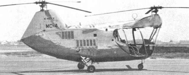
Jovanovich and Kozloski transferred in 1949 to the newly-formed helicopter division of the McCulloch Motors Corporation, where an enlarged development of the JOV-3 was built as the MC-4 with 6.71m rotors and a 165hp Franklin 6V4-165-832 engine. The main drive shaft is driven through a 12-unit vee-belt system. This prototype (N4070K) flew for the first time on March 20, 1951 at Los Angeles, and soon afterwards McCulloch began the construction of a prototype MC-4C (N4071K) and three generally similar YH-30’s (52-5837 to ’39) for evaluation by the U.S. Army. These were slightly larger than the MC-4, having 200hp Franklins and egg-shaped tail fins mounted on outriggers below the rear rotor head. The YH-30’s trials programme yielded no military orders, and no civilian customers were immediately forthcoming for the MC-4C, which was certificated by the CAA on 17 February 1953.
Jovanovich and Kozloski left McCulloch when the Airplane Division was closed, and formed Jovair Corp in 1957 to continue their work on helicopters. They resumed the design rights and purchased one of the MC-4A’s (N4071K) which had been produced for evaluation by the USN (as the HUM-1).
Four-seat 4E Sedan with the 1962-built Jovair 4A, a stripped-down two-seat agricultural and training aircraft
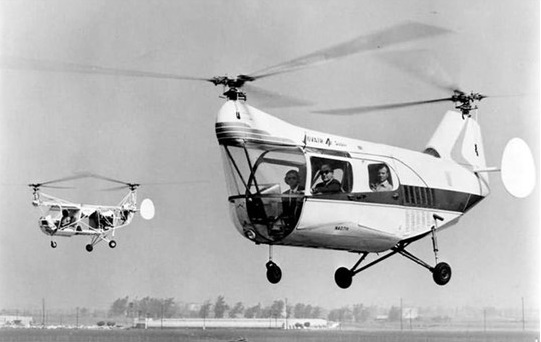
Jovair modified the MC-4C as a prototype for a four-seat private helicopter designated the Sedan 4E. The Sedan 4E was powered by 210 hp Franklin 6A-335 engine and received certification in March 1963. A version with a turbocharged engine was designed as the Sedan 4ES and a more basic Sedan 4A for agricultural use. By 1965 a small number of Sedan helicopters were built. In 1969 McCulloch regained the rights to the helicopter designs who continued development of the Jovair 4E Sedan as the McCulloch MC-4E.
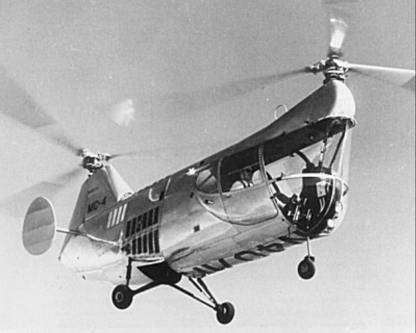
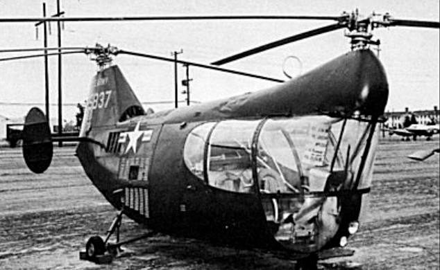
The design was offered to the U.S. Army as the XH-30 (MC-4C, serials 52-5837 through -5839) and to the Navy as the XHUM-1 (MC-4A) by McCulloch Motors Corporation. Three were built for the Army and two for the Navy in 1953. Neither service had a use for them and they were returned to McCulloch.
The YH-30 was a craft of relatively simple construction, consisting of a steel tube framework to which was attached a light metal skin. The helicopter’s single 200hp Franklin engine was mounted horizontally amidships and drove the two inter-meshing tandem rotors through a single horizontal drive shaft and two right-angled reduction units. Two small endplate rudders were fixed to the rear fuselage to provide additional lateral stability, and the aircraft was equipped with wheeled tricycle landing gear. The craft’s two crew members enjoyed better than average visibility to the front and sides, though the view upward was blocked by the overhanging front rotor housing.
The Army’s evaluation of the YH-30 showed the helicopter to be somewhat underpowered and its drive system to be overly complex. The type was therefore not procured in quantity, and the three evaluation machines were declared surplus in mid-1953 and disposed of.
McCulloch MC-4
An MC-4C was used in the 1954 science fiction production Gog.
The civil version, the slightly larger MC-4, was unable to generate any sales and McCulloch lost interest in the project and turned it back over to the original designer D. K. Jovanovich.
Jovair Corporation produced N4071K in developed form as the prototype for a new 4-seat private or executive helicopter known as the Sedan 4E. The Franklin 6A-335 of 210hp was now installed and the fuselage offered comfortable accommodation and easy 4-door access to 3 passengers in addition to the pilot. A supercharged version, the Sedan 4ES, was offered with a 225hp Franklin 6AS-335. The Sedan 4E received type approval from the FAA in March 1963, and some two years later small-scale production of this version was begun; a version, with a 235hp 6A-350 engine, is slightly heavier. In mid-1963 Jovair offered the stripped-fuselage Sedan 4A as an agricultural, training or utility cargo version, with provision for some 450kg of cargo or crop spraying equipment in place of the rear passenger compartment.
Jovair Sedan
Jovair 4E
The Jovair E4 features independently removable components for ease of maintenance, including heavy-duty vibrationless control system, interchangeable rotor balades and ground resonanceless design. Landing gear is fixed type tri-gear. The Jovair Sedan has skinned, steel tube fuselage structure. Rotor blades are all metal using bonded, wrap-around skin construction, factory balanced. A hinged type rotor system is utilised. Vibrationless flexible Vee-belt drive transmits power to the shafts and gears (2 sets of bevel gears used) and one-size flex-spline type coupling replaces universal joints.
In 2008 two MC-4Cs were still registered in the United States. The Pima Air and Space Museum has a HUM-1, registration N4072K (Serial Number: 133817). The Yanks American Air Museum at Chino are restoring a MC-4C to flying condition although they have no plans to fly it. It may be N4071K or N4091K. One of the three YH-30 miitary prototypes is preserved by the US Army Aviation Museum at Fort Rucker, Alabama. It is c/n 001 and has the military serial 52-5837. As of April 2013 it remains in a storage building and is not on public display.
Variants: McCulloch MC-4 Prototype with a 165 hp Franklin engine, two built, one for evaluation by the United States Navy.
McCulloch MC-4A Variant for evaluation by the United States Navy as the XHUM-1, two built.
McCulloch MC-4C Prototype with a 200 hp Franklin engine, one built and an additional three for United States Army evaluation as the YH-30.
Jovair Sedan 4E Production civil four-seat version powered by a 210 hp Franklin 6A-335 engine.
Jovair Sedan 4ES Sedan with a turbocharged 225 hp Franklin engine.
Jovair Sedan 4A Simplified agricultural version.
YH-30 Military version of the MC-4C, three built.
XHUM-1 Two MC-4As for evaluation by the United States Navy, later redesignated HUM-1.
Jim Trego 02.09.2011 I was one of the engineers on the project. There were only 23 people on the project including engineers, welders, mechanics and a test pilot. A real fun project that didn’t go anywhere because the Korean war ended and so did the market for helicopters.
MC-4 Engine: 1 x Franklin 6A4-200-C6, 149kW / 200 hp Rotors: 2 x 3-blade tandem inter-meshing Rotor diameter: 7.01m / 23 ft Fuselage length: 9.88m Height: 2.77m Max take-off weight: 1043kg / 2,300 lb Empty weight: 726kg Max speed: 169km/h / 120 mph Cruising speed: 137km/h Ceiling: 3048m / 10,000 ft Range: 322km / 200 miles at 85 mph with full load Crew: 2
HUM-1 Engines: 1 Franklin 6A4-200-C6 200 hp Rotor diameter: 23 ft Length: 32 ft 5 in Height: 9 ft 3 in Weight: 2,300 lbs Max. Speed: 105 mph Service Ceiling: 8,000 ft Range: 200 miles Crew: 2
YH-30 Powerplant: 1 × Franklin O-335-6 (6A4-200-C6), 200 hp (147.1 kW) Crew: two Length: 32 ft 0 in Main rotor diameter: 2× 22 ft 0 in Height: 9 ft 2 in Empty weight: 1200 lb (544 kg) Gross weight: 2000 lb (907 kg) Maximum speed: 105 mph (168.98 km/h) Range: 200 miles (321.86 km)
Jovair 4E Rotor blade diameter: 23 ft Rotor blades chord: 6.76in Overall width: 18 ft Height: 9 ft Overall length: 33 ft 2 in Fuselage length: 18 ft Empty weight: 1463 lb Useful load: 837 lb Gross weight: 2300 lb Cruise speed: 90+ mph Endurance: 2 hr Service ceiling: 12,500 ft Hover ceiling IGE: 6000 ft Hover ceiling OGE: 3000 ft Undercarriage tread: 6 ft 6.75 in Undercarriage track: 7 ft Basic price: $48,500