Verville 104 Air Coach

Verville 104-C NX303V

The 104 Air Coach (ATC 267) was built from 1928. With a semi-cantilever wing, the Air Coach was priced at $7,500. Two were built as just Air Coach NX506 c/n 2 and NX151E c/n 1.

Six or seven 104-C Air Coach were built in 1929 at $12,000, including; NC68W=NS11, NC88Y=NS3, NX/NC303H (165hp Wright J-6), X/NC303V, NC356V, NC477Y. ATC 2-306 was for NC477Y, powered by a 240hp Wright R-760 engine.

Verville 104-C NX303V

There was one 104-A Air Coach, converted from 104-C NC68W, in 1933. Registered NS11 (ATC 2-454).

In 1930 104-C NC70W was modified to a 104-P Air Coach (ATC 316) with a 225hp Packard DR-980 diesel.

Verville 104-P NC70W

The 104-P Air Coach was priced at $11,000-12,000 but only the one was produced.

104-A Air Coach
Engine: 220hp Wright J-5
Seats: 4

104-C Air Coach
Engine: 110hp Warner Scarab
Wingspan: 40’0″
Length: 28’0″
Useful load: 875 lb
Max speed: 110 mph
Stall: 45 mph
Range: 600 mi
Seats: 4

104-C Air Coach
Engine: 225hp Wright J-6
Wingspan: 44’0″
Length: 28’9″
Useful load: 1234 lb
Max speed: 130 mph
Cruise speed:110 mph
Stall: 50 mph
Range: 650 mi
Seats: 4

104-P Air Coach
Engine: 225hp Packard DR-980 diesel
Length: 28’8″
Useful load: 1100 lb
Max speed: 130 mph
Cruise speed:110 mph
Stall: 50 mph
Range: 640 mi
Seats: 4

Verville AT Sportsman / AT-4 Sportsman / LT Sportsman / White Aircraft Co AT Sportsman

Verville AT NC450M

The 1930 AT Sportsman (ATC 323) was priced at $5,250. Eleven were built; NC450M-459M c/ns 1-5, 7-10; NC456M c/n 27 wasn’t licensed until 10 June 1931; NC476Y c/n 14; c/n 7 became c/n 27, c/n11 became c/n 20, c/ns 12 and 15/18 were not used, c/n 19 went to the LT.

Basic color scheme for ATs was green/orange for c/ns 1/3, black/orange for c/ns 4 and 27, blue/orange for c/ns 5/6, 8/10, and 19; c/n 13 as described below, others unrecorded. [NC476Y] was customized for Col Robert R McCormick with enlarged cockpits (McCormick weighed 225# stripped), and the ability of plane to be started and flown from both cockpits; special paint scheme: jet black wing and chassis struts; army yellow wings and tail surface; berry red (artillery red) fuselage; silver louvers.

The AT Sportsman design and production rights were sold to White Aircraft Co in 1939.

The sole AT-4 Sportsman of 1930 was for NACA testing. Registered NS478Y c/n 13, it had a modified wide landing gear with added fittings with structural bearing for EDO pontoons, which may or may not have been used, and steel interplane struts. Colors: Blue fuselage, silver wings, yellow stripe.

Verville AT-4 NS478Y

The single LT Sportsman of 1931 was an AT fitted with a 210hp Lycoming R-680 for Lycoming Mfg Co, Williamsport PA. It was registered NX10898 c/n 19.

Verville AT NC450M

AT Sportsman
Engine: 165hp Continental A-70
Wingspan: 31’0″
Length: 24’3″
Useful load: 678 lb
Max speed: 120 mph
Cruise speed: 100 mph
Stall: 50 mph
Range: 370 mi
Seats: 2

LT Sportsman
Engine: 210hp Lycoming R-680
Wingspan: 31’0″
Length: 24’3″

Verville-Packard / R-1

Verville-Packard R-1 AS-40126

Alfred V. Verville is best known for his later Verville-Packard and Verville-Sperry racing aircraft of the early 1920s.

Verville-Packard R-1 AS-40126

The Verville-Packard was modified from Engineering Division VCP-1 AS40126 by Alfred Verville in 1920 and was the 1921 Pulitzer race winner, redesignated R-1.

Verville-Packard R-1 Nose radiator

Engine: Packard V-12, 638hp
Seats: 1

Verville-Packard R-1 AS-40126

Verville-Sperry R-3

Verville-Sperry R-3 1922

On 23 May 1922 Army contract #7388 was awarded to the Lawrence Sperry Aircraft Vo for three special Army Sir Service R-3 racing aircraft. The price was set at $25,000 per aircraft without powerplant. The special Wright H-3 High Compression engines were to be furnished by the Air Service, but installation was to be done by the builder. Serial numbers 22-326, 22-327 and 22-328 were assigned to the three racers. Three propellers were shipped from McCook Field to the Sperry plant in Farmingdale, Long Island, but these were never used. They were but the first of a long series of props designed to get the most out of the special Wright engines.

The Air Service contract with Wright Aeronautical called for modification of three engines originally designed for the MB-3, at $750 engine each. After the 1922 race, they were to be returned to Wright, re-modelled and re-consigned to Boeing Aircraft Co.

Alfred Verville had the R-3 design finalised, the work got underway at the Sperry plant. Things progressed normally except for a few items. There were no 200mph airspeed indicators. But Pioneer Instrument Company built enough for the planes entered in the Pulitzer race.

New birch propellers were ordered from the Hartzell Walnut Propeller outfit on 18 August. It was decided that several different props would afford a better test range, so two of the new props were 99 inch in diameter, 100 inc pitch, the other two 96 inch in diameter with 104.5 inch pitch. Whirl tests were to be conducted on all, and if they did not turn 2000 rpm, they would be trimmed until they did. Trhee props were delivered to Sperry on 15 September. But just three days before that, the Engineering Division at McCook Field notified the contractor that they had designed four different type of props and were building them at McCook Field.

Verville-Sperry R-3 Prep for 1923 St Louis Air Meet

The first was refitted with a 500hp Curtiss D-12 in 1923 and won the Pulitzer Trophy in 1924 at 216.5 mph.

Verville-Sperry R-3 Advertising art

Engine: 400hp Wright H-3
Wingspan: 29’3″
Length: 22’5″
Speed: 191 mph
Seats: 1

Vertol 76 / VZ-2

Vertol began involvement with Tilt-Wing investigations in the 1950s with work on its company-designated Model 76 program. The research would be affirmed with a joint Army/Navy contract, signed on April 15, 1956, for a tilt wing convertiplane, defined as the VZ-2A program. The design and development contract was for $850,000.

This VTOL configuration had not previously been tested in flight and the object of the programme was to build a test bed as quickly and as simply as possible. This was achieved by using available parts for several components – ¬a Bell helicopter canopy, wing actuators from the Piasecki XH 16, Piasecki HUP helicopter tail oleo struts as main undercarriage legs on the test bed and a number of parts from the Piasecki H 21. The Vertol Model 76, as the VZ 2 was known, was ready for flight in less than a year from the contract being placed.

The principal advantage of the tilt wing type of convertiplane is that it can be in most respects a conventional aircraft for cruising flight and therefore has good performance. In this respect it is similar to the tilting rotor type such as the Bell XV 3, there being some advantage in having the rotor/propeller assembly solid with the wing and tilting the whole component.

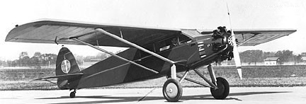
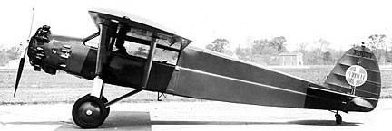
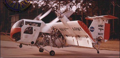
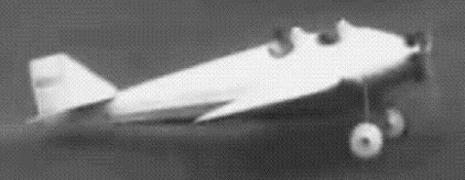
The vehicle, with much of the fuselage being of open-tubular construction, had a cockpit located far forward of the wing pivot point and featuring side-by-side seating for the two-man crew.

There were dual controls which could move control surfaces on the vertical stabilizer topped with a flat horizontal “T” configuration. The complexity of the concept was increased with the addition of a pair of ducted fans for pitch and yaw control, both being located in the tail.

A 660 horsepower Lycoming YT53-L-1 turboshaft was mounted by struts above the fuselage. The exhaust was vented outward to the left side of the rear stabilizer. Since the propellers were not attached to actual engines, the units that transferred the power from the fuselage-mounted engine resulted in considerably smaller wing units.
A portion of the turbine power was also transmitted through shafting to two ducted fans, one in the vertical and the other in the horizontal stabilizer. These fans, through a pitch-changing mechanism, were used for pitch and yaw control of the craft during hovering and transition flight.

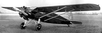
Through a complex system which incorporated a cross shaft arrangement, the power was transferred to the pair of wing-mounted rotors which were located close to the center point of each wing. The rotors were large in diameter, at nine and one-half feet in span, and each carried three blades. The variable-pitch rotors, in addition to their primary power requirement, also provided supplemental roll control.

The craft proved to be extremely maneuverable, but was extremely slow with a maximum speed of only 215km/h. For safety purposes, the propellers were interconnected.

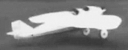
For aerodynamic reasons, the rear fuselage of the plane would later be skinned for smoother air flow.

Vertol test pilot Leonard La Vassar made the first flight in the VZ 2 (single example produced 56 6943) on April 13th, 1957, with the wings fixed for vertical flight. On January 7th, 1958, he made the first flight with wings horizontal and then set about ‘closing the gap’ to achieve a full transition in flight. This he did on July 15th, 1958.

Between then and September 23rd, 1959, Vertol completed 30 hours’ flying and then delivered the VZ 2 to N.A.S.A. at Langley Research Center. The first stage of N.A.S.A. testing involved another 20 hours’ flying in the next year. In this period, several modifications were introduced. A Martin Baker ejection seat was fitted changing the contours of the cockpit the rear fuselage was covered in and additional dorsal and ventral fin area was fitted.

N.A.S.A. also fitted a droop snoot leading edge to the wing. This was designed to delay the stall of the wing, which occurred initially at an incidence of 25 30 degrees, causing buffeting and control difficulties. In May 1961, Vertol was granted a new contract covering further modifications, including fitting of trailing edge flaps on the wing, which was originally flapless. With flaps, the aircraft has some characteristics of the deflected slipstream types and the stalling characteristics of the wing are further improved.

Another modification in the 1961 programme was to increase the rating of the Lycoming to 700 h.p. After testing by Vertol, the VZ 2A was returned to Langley Field. At the time the contract was placed, 448 flights had been made in the 50 hours, and 34 full and 239 partial conversions had been made.

Upon its retirement, the VZ-2A was given a place at the Smithsonian Institution.

Gallery

VZ-2A
Engine: Lycoming YT-53-L-1, 630kW / 860-shp
Rotor diameter: 2.90m
Wingspan: 7.60m
Fuselage length: 8.2m
Height: 3.15m
Take-off weight: 1443kg
Empty weight: 1128kg

Vertol 44

In 1958 New York Airways introduced the Vertol 44 single engine, tandem rotor helicopter into scheduled service, in and around the New York metropolitan area.

1955 Royal Swedish Navy
Two were used by the French Government as VIP transport

44
Engine: 1275hp Wright R-1820
Rotor diameter: 44’0″
Length: 52’6″
Useful load: 5420 lb
Max speed: 127 mph
Cruise speed: 101 mph
Range: 360 mi

44A
19p cargo version

44B
15p passenger version.

44C
Deluxe version of 44B

Vertical Aviation Technologies Hummingbird

The Hummingbird helicopter kit programme began in 1988. A 4 place helicopter based on a Sikorsky S-52. Of aluminium construction with carbon-graphite composite nose, powered by an aluminium 6.5 lt V8 of 260hp. Rotor mechanics remained the original.

Hummingbird

By 1995, equipped with an electric cyclic trim system and hydraulic driven radiator fan. This helicopter was still available in fit form in 2004.

After a break in production of six years the company produced a new and improved Hummingbird in 1991, the 260L.
The Hummingbird 260L is a highly modified version of the four place Sikorsky S 52¬-3 with major changes to the nose, windshield, and powerplant installation turned into a kit. A modification has been the installation of a 260 h.p. Lycoming powerplant. The Hummingbird 260L is an FAA approved helicopter combined with an FAA approved powerplant. The Lycoming VO 435 A1F was designed to operate in an oblique position. One version can be turbo charged to 280 h.p. The Lycoming VO 435 A1F can be operated with automobile gasoline making it “fuel friendly”, where Avgas availability is limited. This entire powerplant installation was designed to meet the requirements of FAR 27 regulation standards for all helicopters in the Western world.
Another change to the new Hummingbird is the composite cabin doors and vertical/ horizontal stabilisers. The tail stabilisers were designed to increase lateral and longitudinal stability, increase tail rotor effectiveness, and reduce weight on the tail of the helicopter. Most components have a time/life of 1200 hours. New blade design will most likely extend blade life to 2000 hrs. A set of three main rotor blades costs about a third of the price of those for a comparable four place piston engine helicopter, with the total aircraft price less than half. The Hummingbird has strength inherent in its basic design. With a payload of over 900lbs, it will take a good size sling load, and with a quick removal of the rear seats, the “utility” configuration means bulky cargo can be carried. Also long range fuel tanks have just been designed as an extra.
As a Kit, the helicopter fits into the Amateur Built/Experimental Category and most of the maintenance can be done by the owner/assembler.

The Hummingbird is a single engine, single three-bladed main rotor type helicopter, with a tail rotor. The fuselage is made of aluminum and composites. The Hummingbird is powered by a FAA approved Lycoming aircraft engine. The transmission system consists of a clutch/freewheel unit between the engine and main gearbox, a main driveshaft extending from the top of the main gearbox to the main rotorhead, and a take-off drive from the main gearbox which drives the tail rotor driveshaft, intermediate gearbox and tail rotor assembly. These parts are manufactured to FAA design standards.
The Hummingbird cabin sits four people. The cabin is 55 inches wide, 56 inches high from floor to ceiling, and 110 inches in length. Two baggage areas 15” L x 20” W x 13” H are located under the forward two seats. Fly two people, 375 miles, with 220 lbs. of camping gear.
The many prefabricated components of the Hummingbird 260L make the kit an easy project for the first time builder. The average build time is 800 hours. There is no welding or composite work, only minor fabrication, and all major components are pre-assembled. The rotor blades for example come to you painted, balanced, and ready for installation. These blades have 7 degrees of twist to enhance performance.
The Hummingbird helicopter kit is assembled in 14 easy to follow sections. The first section consists of building the lower cabin. In this section, you will learn about real aircraft sheet metal fabrication and aircraft assembly. In the next section you will receive the upper cabin assembled.
After fitting the upper and lower cabin together, the landing gear is next, and then the nose. Flight controls, electrical components, instrumentation and fuel systems are next for installation.
The tailcone section is supplied assembled to assure uniformity. The powerplant and gearboxes are assembled for installation when received.
The main rotor blades and tail rotor blades will then come to you completely ready to install in the fully articulated rotor head. They will have been painted and pre-balanced at our factory. After rigging all the flight controls and cables, and calculating the Hummingbird’s weight and balance, it’s ready to fly.
Because of its inherently long tail, forward flight is very stable but very agile. The flight control system incorporates electric trim with force gradient spring pressure. Stick forces are very light. An appealing characteristic is the landing gear that is able to taxi and not have to hover, with hydraulic brakes and shock absorbing struts. The three blade rotor system is very smooth and has a medium inertia rotor providing excellent autorotation characteristics. The clutch is automatic for engaging the rotor system and a rotorbrake is included to slow the rotor during shut down.

Hummingbird
Engine: Aluminium V-8, 260 hp
hp range 260-315
Empty wt: 1,800 lb
Max wt: 2,700 lb
Rotor span: 33ft
Length: 30’6”
Height: 8’2”
Width: 8’7”
Service Ceiling: 11,000 ft
Max speed: 110 mph
Cruise: 90-95 mph
Range: 450 sm
Seats: 4
ROC: 1200 fpm
Fuel cap: 57 USG

Hummingbird
Engine: V8 6.5 lt, 260 hp
Rotor span: 10.05 m
MAUW: 1223 kg
Empty weight: 815 kg
Fuel capacity: 215 lt
Max speed: 176 kph
Cruise speed: 150 kph
Minimum speed: 0 kph
Climb rate: 4.75 m/s
Seats: 4
Fuel consumption: 50 lt/hr
Kit price (1998): $140,500

Hummingbird 260L
Engine: Lycoming V0-435
Rotor Blades: 3-blade
Main rotor dimension 33′ 0″
Tail rotor dimension 5′ 9″
Fuselage length 30′ 6″
Height 8′ 7″
Width 5′
Empty Weight 1,800 lbs
Useful Load 900 lbs
Gross Weight 2,700 lbs
Fuel 57 USG
Min Speed Hover
Vne 132 mph
Cruise 90-95 mph
Top Speed 110 mph
Rate of climb 1250 fpm at 2300 lb
Rate of climb 950 fpm at 2700 lb
Service ceiling 14,000 ft
Range 375 Miles
Kit: $169,000 in 2009.
Seats: 4

Vermont Gull Wing

Schill Gull Wing NX6929

The 1929 Vermont Air Transport Co Gull Wing was constructed at Harrison NJ. The four place Gull Wing featured two side-by-side cockpits. Wide-chord, birdlike wings permitted landings in 300-400′.

The one built NX6929, planned for entry in the Guggenheim competition, but was damaged beyond repair in a rough-field landing at St Albans VT.

Schill Gull Wing NX6929

Engine: Anzani
Max speed: 80 mph
Stall: 30 mph
Seats: 4